CN211964177U - Reaction unit for chemical production - Google Patents
Reaction unit for chemical production Download PDFInfo
- Publication number
- CN211964177U CN211964177U CN202020464625.4U CN202020464625U CN211964177U CN 211964177 U CN211964177 U CN 211964177U CN 202020464625 U CN202020464625 U CN 202020464625U CN 211964177 U CN211964177 U CN 211964177U
- Authority
- CN
- China
- Prior art keywords
- reaction
- wall
- cabinet body
- chemical production
- waste heat
- Prior art date
- Legal status (The legal status is an assumption and is not a legal conclusion. Google has not performed a legal analysis and makes no representation as to the accuracy of the status listed.)
- Active
Links
Images


Abstract
The utility model discloses a reaction device for chemical production, which comprises a reaction mechanism and a waste heat recovery mechanism, wherein the waste heat recovery mechanism is connected with the reaction mechanism through a communicating pipe; evenly be provided with a plurality of flexible (mixing) shafts in the outer wall both sides of bull stick, and per two flexible (mixing) shafts's the outside all is connected with the scraper blade for when the device reaction, not only can be through flexible (mixing) shaft with industrial chemicals stirring, improve reaction quality, can also improve utilization of raw materials through the defective material of scraper blade clearing device inner wall in good time when the stirring. The device is provided with a plurality of heat exchange tubes in the inner chamber of the cabinet body, and runs through the inner chamber of the through-hole and the intercommunication cabinet body communicating pipe for the cauldron body is at the during operation, can let in the inner chamber of the cabinet body through communicating pipe with the heat that the reaction produced in time, utilizes the heat exchange tube to carry out waste heat utilization simultaneously, reduces calorific loss, has also greatly improved the waste heat utilization ratio that the reaction produced.
Description
Technical Field
The utility model relates to a chemical industry utensil technical field specifically is a reaction unit for chemical production.
Background
The broad understanding of the reaction kettle is that the reaction kettle is a container for physical or chemical reaction, and the heating, evaporation, cooling and low-speed mixing functions required by the process are realized through the structural design and parameter configuration of the container. The reaction kettle is widely applied to pressure vessels for petroleum, chemical engineering, rubber, pesticides, dyes, medicines and foods, and is used for completing technological processes such as vulcanization, nitration, hydrogenation, alkylation, polymerization, condensation and the like, such as a reactor, a reaction kettle, a decomposition kettle, a polymerization kettle and the like; the material is generally carbon manganese steel, stainless steel, zirconium, nickel-based (Hastelloy, Monel, Inconel) alloy and other composite materials.
Most of existing reaction devices for chemical production are low in waste heat utilization rate, and partial reaction raw materials are easy to remain on the inner wall and the bottom of the device.
Aiming at the problems and the challenges, the reaction device for chemical production has the advantages of high waste heat utilization rate, difficulty in remaining partial reaction raw materials on the inner wall and the bottom of the device and the like.
SUMMERY OF THE UTILITY MODEL
An object of the utility model is to provide a reaction unit for chemical production, it has the higher and inner wall and the difficult advantage such as residual part reaction raw materials of bottom of device of waste heat utilization ratio to solved traditional reaction unit for chemical production, the lower and inner wall of device of most waste heat utilization ratio and the easy problem of residual part reaction raw materials in bottom.
In order to achieve the above object, the utility model provides a following technical scheme: a reaction device for chemical production comprises a reaction mechanism and a waste heat recovery mechanism, wherein the waste heat recovery mechanism is connected with the reaction mechanism through a communicating pipe, the reaction mechanism comprises a sealing cover structure, a kettle body and a waste gas treatment box, the sealing cover structure is fixedly connected to the upper end of the kettle body, the waste gas treatment box is arranged on the outer wall of one side of the kettle body, an alkali liquor inlet is arranged at the input end of the waste gas treatment box, an outlet pipe is arranged at the bottom end of the waste gas treatment box, and a discharge pipe is arranged at the bottom end of the kettle body;
the waste heat recovery mechanism comprises an upper cover and a cabinet body, a water inlet and a water outlet are respectively formed in the outer wall of one side of the cabinet body, a cabinet door is installed at the front end of the cabinet body, and a plurality of heat exchange tubes are arranged in the inner cavity of the cabinet body.
Further, sealed lid structure comprises gear motor, drive shaft, bull stick and sealed lid, and gear motor electric connection drive shaft, the lower extreme of drive shaft are connected with the bull stick, and the bull stick runs through sealed lid and lies in the inner chamber of the cauldron body, and the surface of sealed lid is provided with the feed inlet.
Furthermore, stirring blades are welded on the outer wall of the bottom end of the rotating rod, and the shape of each stirring blade is a spiral shape.
Furthermore, a plurality of telescopic stirring shafts are uniformly arranged on two sides of the outer wall of the rotating rod, and the outer sides of every two telescopic stirring shafts are connected with scraping plates.
Further, the surface of the scraper is provided with a non-slip pad, and the non-slip pad is a member made of a polyester sponge material.
Furthermore, a through hole is formed in the outer wall of one side of the upper cover, and the communicating pipe penetrates through the through hole and is communicated with the inner cavity of the cabinet body.
Compared with the prior art, the beneficial effects of the utility model are as follows:
1. this reaction unit for chemical production is provided with a plurality of heat exchange tubes in the inner chamber of the cabinet body, and runs through the inner chamber of the through-hole and the intercommunication cabinet body communicating pipe for the cauldron body can let in the inner chamber of the cabinet body through communicating pipe with the heat that the reaction produced in time at the during operation, utilizes the heat exchange tube to carry out waste heat utilization simultaneously, reduces calorific loss, has also greatly improved the waste heat utilization who reacts the production.
2. This reaction unit for chemical production evenly is provided with a plurality of flexible (mixing) shafts in the outer wall both sides of bull stick, and the outside of per two flexible (mixing) shafts all is connected with the scraper blade for when the device reaction, not only can be through flexible (mixing) shaft with industrial chemicals stirring, improve reaction quality, can also be in good time when the stirring through the incomplete material of scraper blade clearing device inner wall, improve material utilization.
3. This reaction unit for chemical production, surface mounting at the scraper blade has the slipmat, and the welding has stirring vane on the bottom outer wall of bull stick, stirring vane's shape is for coiling the heliciform, not only makes when utilizing scraper blade cleaning device inner wall, can avoid the direct and device inner wall contact of scraper blade through the slipmat, can also carry out intensive mixing in promoting the remaining industrial chemicals of bottom in the cauldron through stirring vane in time, reduced material cost, also improved material utilization.
Drawings
Fig. 1 is a schematic view of the overall structure of the present invention;
FIG. 2 is a schematic structural view of the waste heat recovery mechanism of the present invention;
FIG. 3 is a schematic structural view of the reaction mechanism of the present invention;
fig. 4 is a schematic structural view of the sealing cover of the present invention;
fig. 5 is an enlarged schematic view of the position a of the present invention.
In the figure: 1. a reaction mechanism; 11. a sealing cover structure; 111. a reduction motor; 112. a drive shaft; 113. a rotating rod; 1131. a stirring blade; 1132. a telescopic stirring shaft; 11321. a squeegee; 1132A, a non-slip mat; 114. a sealing cover; 1141. a feed inlet; 12. a kettle body; 121. a discharge pipe; 13. a waste gas treatment tank; 131. an alkali liquor inlet; 132. an outlet pipe; 2. a waste heat recovery mechanism; 21. a communicating pipe; 22. an upper cover; 221. a through hole; 23. a cabinet body; 231. a water inlet; 232. a water outlet; 233. a cabinet door; 234. a heat exchange tube.
Detailed Description
The technical solutions in the embodiments of the present invention will be described clearly and completely with reference to the accompanying drawings in the embodiments of the present invention, and it is obvious that the described embodiments are only some embodiments of the present invention, not all embodiments. Based on the embodiments in the present invention, all other embodiments obtained by a person skilled in the art without creative work belong to the protection scope of the present invention.
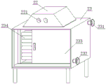
Please refer to fig. 1 and fig. 3, a reaction device for chemical production, including reaction mechanism 1 and waste heat recovery mechanism 2, waste heat recovery mechanism 2 connects reaction mechanism 1 through communicating pipe 21, reaction mechanism 1 includes sealed lid structure 11, the cauldron body 12 and exhaust-gas treatment case 13, sealed lid structure 11 fixed connection is in the upper end of the cauldron body 12, be provided with exhaust-gas treatment case 13 on one side outer wall of the cauldron body 12, alkali lye import 131 is installed to the input of exhaust-gas treatment case 13, the bottom of exhaust-gas treatment case 13 is provided with outlet pipe 132, and discharging pipe 121 is installed to the bottom of the cauldron body 12.
Referring to fig. 2, in a reaction device for chemical production, a waste heat recovery mechanism 2 includes an upper cover 22 and a cabinet body 23, a water inlet 231 and a water outlet 232 are respectively arranged on an outer wall of one side of the cabinet body 23, a cabinet door 233 is installed at the front end of the cabinet body 23, and a plurality of heat exchange tubes 234 are arranged in an inner cavity of the cabinet body 23; a through hole 221 is formed on an outer wall of one side of the upper cover 22, and the communication pipe 21 penetrates through the through hole 221 and is communicated with the inner cavity of the cabinet 23.
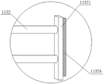
Referring to fig. 4-5, in a reaction apparatus for chemical production, a sealing cover structure 11 is composed of a speed reduction motor 111, a driving shaft 112, a rotating rod 113 and a sealing cover 114, the speed reduction motor 111 is electrically connected to the driving shaft 112, the lower end of the driving shaft 112 is connected to the rotating rod 113, the rotating rod 113 penetrates through the sealing cover 114 and is located in an inner cavity of the kettle body 12, and a feeding hole 1141 is formed in the surface of the sealing cover 114; the outer wall of the bottom end of the rotating rod 113 is welded with a stirring blade 1131, and the shape of the stirring blade 1131 is a spiral shape; a plurality of telescopic stirring shafts 1132 are uniformly arranged on two sides of the outer wall of the rotating rod 113, and the outer sides of every two telescopic stirring shafts 1132 are connected with scrapers 11321; the surface of the blade 11321 is mounted with a cleat 1132A, and the cleat 1132A is made of a member made of a polyester sponge material.
In summary, the following steps: according to the reaction device for chemical production, the sealing cover structure 11 is fixedly connected to the upper end of the kettle body 12, the plurality of telescopic stirring shafts 1132 are uniformly arranged on two sides of the outer wall of the rotating rod 113, and the outer sides of every two telescopic stirring shafts 1132 are connected with the scrapers 11321, so that when the device is used for reaction, chemical raw materials can be uniformly stirred through the telescopic stirring shafts 1132, the reaction quality is improved, and the residual materials on the inner wall of the device can be removed through the scrapers 11321 in time during stirring, so that the raw material utilization rate is improved; the surface of the scraper 11321 is provided with a non-slip mat 1132A, the outer wall of the bottom end of the rotating rod 113 is welded with a stirring blade 1131, the shape of the stirring blade 1131 is a spiral shape, so that when the inner wall of the device is cleaned by the scraper 11321, the scraper 11321 can be prevented from directly contacting with the inner wall of the device through the non-slip mat 1132A, chemical raw materials remained at the bottom in the kettle can be lifted up by the stirring blade 1131 in time for sufficient stirring, the raw material cost is reduced, the raw material utilization rate is also improved, the outer wall of one side of the kettle body 12 is provided with an exhaust gas treatment box 13, the input end of the exhaust gas treatment box 13 is provided with an alkali liquor inlet 131, the bottom end of the exhaust gas treatment box 13 is provided with an outlet pipe; be provided with water inlet 231 and delivery port 232 on the one side outer wall of the cabinet body 23 respectively, cabinet door 233 is installed to the front end of the cabinet body 23, and be provided with a plurality of heat exchange tubes 234 in the inner chamber of the cabinet body 23, and communicating pipe 21 runs through-hole 221 and communicates the inner chamber of the cabinet body 23, make the cauldron body 12 at the during operation, can let in the inner chamber of the cabinet body 23 through communicating pipe 21 with the heat that the reaction produced in time, utilize heat exchange tubes 234 to carry out waste heat utilization simultaneously, reduce calorific loss, the waste heat utilization who produces has also greatly improved the reaction.
It is noted that, herein, relational terms such as first and second, and the like may be used solely to distinguish one entity or action from another entity or action without necessarily requiring or implying any actual such relationship or order between such entities or actions. Also, the terms "comprises," "comprising," or any other variation thereof, are intended to cover a non-exclusive inclusion, such that a process, method, article, or apparatus that comprises a list of elements does not include only those elements but may include other elements not expressly listed or inherent to such process, method, article, or apparatus.
Although embodiments of the present invention have been shown and described, it will be appreciated by those skilled in the art that changes, modifications, substitutions and alterations can be made in these embodiments without departing from the principles and spirit of the invention, the scope of which is defined in the appended claims and their equivalents.
Claims (6)
1. The utility model provides a reaction unit for chemical production, includes reaction mechanism (1) and waste heat recovery mechanism (2), waste heat recovery mechanism (2) are through connecting reaction mechanism (1), its characterized in that communicating pipe (21): the reaction mechanism (1) comprises a sealing cover structure (11), a kettle body (12) and a waste gas treatment box (13), the sealing cover structure (11) is fixedly connected to the upper end of the kettle body (12), the waste gas treatment box (13) is arranged on the outer wall of one side of the kettle body (12), an alkali liquor inlet (131) is installed at the input end of the waste gas treatment box (13), an outlet pipe (132) is arranged at the bottom end of the waste gas treatment box (13), and a discharge pipe (121) is installed at the bottom end of the kettle body (12);
the waste heat recovery mechanism (2) comprises an upper cover (22) and a cabinet body (23), a water inlet (231) and a water outlet (232) are respectively arranged on the outer wall of one side of the cabinet body (23), a cabinet door (233) is installed at the front end of the cabinet body (23), and a plurality of heat exchange tubes (234) are arranged in the inner cavity of the cabinet body (23).
2. The reaction device for chemical production according to claim 1, characterized in that: sealed lid structure (11) comprises gear motor (111), drive shaft (112), bull stick (113) and sealed lid (114), gear motor (111) electric connection drive shaft (112), and the lower extreme of drive shaft (112) is connected with bull stick (113), and bull stick (113) run through sealed lid (114) and lie in the inner chamber of the cauldron body (12), and the surface of sealed lid (114) is provided with feed inlet (1141).
3. The reaction device for chemical production according to claim 2, characterized in that: stirring blades (1131) are welded on the outer wall of the bottom end of the rotating rod (113), and the shape of each stirring blade (1131) is in a spiral shape.
4. The reaction device for chemical production according to claim 2, characterized in that: the outer wall both sides of bull stick (113) evenly are provided with a plurality of flexible (mixing) shaft (1132), and the outside of per two flexible (mixing) shaft (1132) all is connected with scraper blade (11321).
5. The reaction device for chemical production according to claim 4, wherein: the surface of the scraper (11321) is provided with a non-slip pad (1132A), and the non-slip pad (1132A) is a member made of a polyester sponge material.
6. The reaction device for chemical production according to claim 1, characterized in that: a through hole (221) is formed in the outer wall of one side of the upper cover (22), and the communicating pipe (21) penetrates through the through hole (221) and is communicated with the inner cavity of the cabinet body (23).
Priority Applications (1)
| Application Number | Priority Date | Filing Date | Title |
|---|---|---|---|
| CN202020464625.4U CN211964177U (en) | 2020-04-02 | 2020-04-02 | Reaction unit for chemical production |
Applications Claiming Priority (1)
| Application Number | Priority Date | Filing Date | Title |
|---|---|---|---|
| CN202020464625.4U CN211964177U (en) | 2020-04-02 | 2020-04-02 | Reaction unit for chemical production |
Publications (1)
| Publication Number | Publication Date |
|---|---|
| CN211964177U true CN211964177U (en) | 2020-11-20 |
Family
ID=73383135
Family Applications (1)
| Application Number | Title | Priority Date | Filing Date |
|---|---|---|---|
| CN202020464625.4U Active CN211964177U (en) | 2020-04-02 | 2020-04-02 | Reaction unit for chemical production |
Country Status (1)
| Country | Link |
|---|---|
| CN (1) | CN211964177U (en) |
Cited By (2)
| Publication number | Priority date | Publication date | Assignee | Title |
|---|---|---|---|---|
| CN113797868A (en) * | 2021-10-13 | 2021-12-17 | 山东省舜天化工集团有限公司 | Melamine thermal reaction kettle with heat energy recovery assembly |
| CN115235268A (en) * | 2022-09-23 | 2022-10-25 | 徐州工业锅炉有限公司 | Flue gas treatment device of industrial boiler |
-
2020
- 2020-04-02 CN CN202020464625.4U patent/CN211964177U/en active Active
Cited By (3)
| Publication number | Priority date | Publication date | Assignee | Title |
|---|---|---|---|---|
| CN113797868A (en) * | 2021-10-13 | 2021-12-17 | 山东省舜天化工集团有限公司 | Melamine thermal reaction kettle with heat energy recovery assembly |
| CN113797868B (en) * | 2021-10-13 | 2022-09-23 | 山东省舜天化工集团有限公司 | Melamine thermal reaction kettle with heat energy recovery assembly |
| CN115235268A (en) * | 2022-09-23 | 2022-10-25 | 徐州工业锅炉有限公司 | Flue gas treatment device of industrial boiler |
Similar Documents
| Publication | Publication Date | Title |
|---|---|---|
| CN211964177U (en) | Reaction unit for chemical production | |
| CN209901291U (en) | Additive reation kettle convenient to clearance | |
| CN211754948U (en) | Reation kettle for chemical industry convenient to wash inner wall | |
| CN210385856U (en) | Reation kettle is used in production of high-purity terpineol | |
| CN210473952U (en) | High performance reation kettle agitator for chemical machinery | |
| CN212468101U (en) | Reation kettle for chemical industry with self-cleaning effect | |
| CN213824755U (en) | Chemical heating reaction pot convenient to automatically scrape materials | |
| CN214131619U (en) | High-pressure reaction kettle | |
| CN209791546U (en) | Disproportionation reaction kettle for silicone oil production | |
| CN212237250U (en) | High-pressure chemical device capable of safely relieving pressure | |
| CN213995844U (en) | Chemical industry reation kettle of rapid heating | |
| CN210206818U (en) | Chemical machinery heat preservation reation kettle convenient to wash | |
| CN218189600U (en) | Bactericide production reation kettle | |
| CN213348894U (en) | Reaction kettle | |
| CN213699821U (en) | Fluorosilicone copolymer reaction kettle | |
| CN218189670U (en) | Steam heating device for refining kettle | |
| CN213699836U (en) | Take cleaning function's chemical industry reation kettle | |
| CN215655156U (en) | Stable form chemical industry reation kettle of high-efficient stirring | |
| CN214210482U (en) | Coil pipe type reaction kettle | |
| CN212092283U (en) | Reation kettle with cleaning function | |
| CN216063217U (en) | Safe reaction kettle for preparing acrylic emulsion | |
| CN214716565U (en) | Water purification agent production reation kettle with heating function | |
| CN213854493U (en) | Reation kettle is used in pesticide processing | |
| CN210646374U (en) | A from washing reation kettle for producing medical intermediate | |
| CN220531602U (en) | Chlorination reaction device for producing modified chlorinated polyethylene |
Legal Events
| Date | Code | Title | Description |
|---|---|---|---|
| GR01 | Patent grant | ||
| GR01 | Patent grant | ||
| PE01 | Entry into force of the registration of the contract for pledge of patent right |
Denomination of utility model: A reaction device for chemical production Effective date of registration: 20230727 Granted publication date: 20201120 Pledgee: Guangfa Bank Co.,Ltd. Dalian Branch Pledgor: DALIAN CHEMICAL INSTITUTE CO.,LTD. Registration number: Y2023210000184 |
|
| PE01 | Entry into force of the registration of the contract for pledge of patent right |