CN211947677U - Cloth cutting mechanism for production - Google Patents
Cloth cutting mechanism for production Download PDFInfo
- Publication number
- CN211947677U CN211947677U CN201922313861.6U CN201922313861U CN211947677U CN 211947677 U CN211947677 U CN 211947677U CN 201922313861 U CN201922313861 U CN 201922313861U CN 211947677 U CN211947677 U CN 211947677U
- Authority
- CN
- China
- Prior art keywords
- cutting
- cloth
- top surface
- roller
- movable block
- Prior art date
- Legal status (The legal status is an assumption and is not a legal conclusion. Google has not performed a legal analysis and makes no representation as to the accuracy of the status listed.)
- Expired - Fee Related
Links
Images


Landscapes
- Treatment Of Fiber Materials (AREA)
Abstract
The utility model discloses a cloth cutting mechanism for production, which comprises a workbench for cutting cloth, wherein a cutting groove is arranged on the top surface of the workbench under a cutting knife, movable grooves are arranged on the inner walls of two sides far away from the cutting groove, a roller rod is arranged in the movable groove through a rotating shaft, the outer side of the roller rod is flush with the top surface of the workbench, a torsional spring is sleeved on the outer wall of the rotating shaft, two ends of the torsional spring are respectively fixed with the outer wall of the rotating shaft and the end part of the roller rod, an anti-slip sleeve made of rubber is sleeved on the outer wall of the roller rod, a torsion bar is hinged at the middle part of the bottom side of the roller rod, one end of the torsion bar far away from the roller rod is hinged with a movable block, two sides of the movable block are respectively attached with the outer walls of the two roller rods, a reset spring is fixed on the bottom side of the movable block, a shearing groove is arranged on the top surface of the, and the structure is simple, and the working process does not need human interference.
Description
Technical Field
The utility model relates to a cloth processing correlation technique field specifically is a cloth cutting mechanism is used in production.
Background
The cloth is in order to satisfy the needs of use and storage in the production and processing process, need carry out certain cutting to the cloth, its principle of cutting mainly is that the cutting blade can make the cloth receive a shearing force when exerting pressure to the cloth, and then realize cutting to the cloth, however, the cloth can take place certain deformation by self when receiving the shearing force, the department of cutting that leads to the cloth is untidy, and can reduce the efficiency of the normal transmission of cloth, so the cloth that can make the department of cutting neat and can not reduce cloth transmission efficiency cuts the mechanism urgently needed.
SUMMERY OF THE UTILITY MODEL
An object of the utility model is to provide a production is with cloth cutting mechanism to current cloth cutting mechanism who proposes leads to the problem that the cloth tangent plane is irregular and influence cloth transmission efficiency easily among the above-mentioned background art of solution.
In order to achieve the above object, the utility model provides a following technical scheme: the utility model provides a production is with cloth cutting mechanism, includes the workstation that is used for cutting the cloth, the top surface of workstation has been seted up under cutting the sword and has been cut the groove, the length of cutting the groove is unanimous with the width of workstation, cut the both sides inner wall that the groove was kept away from mutually and have all seted up movable groove, can install through the pivot in the inside in movable groove and can be in its inside free rotation's roller bar, the middle part department of roller bar bottom side articulates there is the torsion bar that can freely deflect, the one end that the roller bar was kept away from to the torsion bar articulates there is the movable block, the groove has been sheared to the top surface of movable block.
Preferably, the outside of roller pole flushes with the top surface of workstation, the outer wall of pivot has cup jointed the torsional spring, the both ends of torsional spring respectively with the outer wall of pivot and the end fixing of roller pole.
Preferably, the roller rod is of a half cylindrical structure, and the outer wall of the roller rod is sleeved with the anti-slip sleeve made of rubber.
Preferably, two sides of the movable block are respectively attached to the outer walls of the two roller rods, a return spring is fixed to the bottom side of the movable block, and one end, far away from the movable block, of the return spring is fixed to the inner wall of the bottom side of the cutting groove.
Preferably, the top surface of the movable block is flush with the top surface of the workbench.
Compared with the prior art, the beneficial effects of the utility model are that:
1. the utility model discloses, through the extrusion of cutting the sword to the cloth for the cloth gets into to the inside of cutting out the groove, then through the drive of torsion bar, makes the roller bar rotate, and the roller bar that is located two lateral walls in cutting out the groove is with the cloth tractive on workstation surface to the inside of cutting out the groove, and makes the tension of cutting sword both sides cloth the same, can make the tangent plane of cloth neat, and can not influence the transmission efficiency of cloth, and simple structure need not artificial interference.
2. The utility model discloses, stretch into the inside of shearing the groove through cutting the sword, can increase the shearing force that the cloth received for cut the sword and cut more rapidly to the cloth, can effectively reduce the production of filoplume.
Drawings
FIG. 1 is a schematic structural view of a workbench according to an embodiment of the present invention;
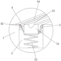
FIG. 2 is an enlarged view of the embodiment A of the present invention;
fig. 3 is the utility model discloses workstation horizontal cut structure schematic diagram.
In the figure: 1. a work table; 2. cutting knife; 3. cutting a groove; 4. a movable groove; 41. a rotating shaft; 42. a roll bar; 43. a torsion spring; 44. an anti-slip sleeve; 5. a torsion bar; 51. a movable block; 52. a return spring; 53. and (6) shearing the groove.
Detailed Description
In order to enable the tangent plane of the cloth to be neat and not to influence the efficiency of cloth transmission, the cloth cutting mechanism for production is particularly provided. The technical solutions in the embodiments of the present invention will be described clearly and completely with reference to the accompanying drawings in the embodiments of the present invention, and it is obvious that the described embodiments are only some embodiments of the present invention, not all embodiments. Based on the embodiments in the present invention, all other embodiments obtained by a person skilled in the art without creative work belong to the protection scope of the present invention.
Example 1
Referring to fig. 1-3, the present embodiment provides a cloth cutting mechanism for production, including a workbench 1 for cutting cloth, a cutting groove 3 is formed on the top surface of the workbench 1 under a cutting knife 2, the length of the cutting groove 3 is consistent with the width of the workbench 1, movable grooves 4 are formed on the inner walls of two sides of the cutting groove 3 away from each other, a roller rod 42 capable of freely rotating inside the movable grooves 4 is installed inside the movable grooves 4 through a rotating shaft 41, a torsion bar 5 capable of freely deflecting is hinged at the middle part of the bottom side of the roller rod 42, a movable block 51 is hinged at one end of the torsion bar 5 away from the roller rod 42, and a cutting groove 53 is formed on the top surface of the movable block 51.
The outside of roller rod 42 is flush with the top surface of workstation 1, and the outer wall of pivot 41 has cup jointed torsional spring 43, and the both ends of torsional spring 43 are fixed with the outer wall of pivot 41 and the tip of roller rod 42 respectively.
The roller rod 42 is a half cylinder structure, and the outer wall of the roller rod 42 is sleeved with an anti-slip sleeve 44 made of rubber.
Two sides of the movable block 51 are respectively attached to the outer walls of the two roller rods 42, a return spring 52 is fixed on the bottom side of the movable block 51, and one end, far away from the movable block 51, of the return spring 52 is fixed on the inner wall of the bottom side of the cutting groove 3.
The top surface of the movable block 51 is flush with the top surface of the table 1.
In this embodiment, when the cutting blade 2 cuts the fabric, the cutting blade 2 is close to the cutting groove 3 along the vertical direction, when the cutting blade 2 contacts the fabric, the fabric is pressed toward the movable block 51, the movable block 51 is pressed to move toward the inside of the cutting groove 3, at this time, the return spring 52 exerts force, the bottom side of the movable block 51 drives the torsion bar 5 to deflect, the torsion bar 5 drives the roller rod 42 to rotate by taking the rotating shaft 41 as the axis, at this time, the torsion spring 43 exerts force, the roller rod 42 lowers the fabric on the surface of the workbench 1 to pull toward the inside of the cutting groove 3, along with the movement of the cutting blade 2 toward the inside of the cutting groove 3, the bottom end of the cutting blade 2 is attached to the cutting groove 53, and at this time, the fabric is cut by.
After the cloth is cut, the cutting knife 2 is separated from the cutting groove 53 and separated from the cutting groove 3, the movable block 51 loses pressure and resets under the action of the reset spring 52, the roller rod 42 resets along with the resetting of the movable block 51 and the action of the torsion spring 43, the movable block 51 and the roller rod 42 eject the end part of the cut cloth out of the cutting groove 3, after the cloth is ejected out, the end part of the cloth passes through the top end of the cutting groove 3 under the action of the conveying belt and falls onto the workbench 1, the process can be completed instantly, and the purpose that the cloth is cut without affecting cloth transmission can be achieved.
Through the cooperation of above each device use, can make the tangent plane of cloth neat, and can not influence the efficiency of cloth transmission to simple structure, the working process need not artificial interference.
Example 2
Referring to fig. 1-3, a further improvement is made on the basis of embodiment 1: the top surface of movable block 51 flushes with the top surface of workstation 1, and shearing groove 53 has been seted up to the top surface of movable block 51, and the front view of shearing groove 53 is the V font structure, and movable block 51 is arbitrary one kind material in pottery and the rubber all can, stretches into the inside of shearing groove 53 through cutting sword 2, can increase the shearing force that the cloth received for it is more rapid to cut of cloth to cut sword 2, can effectively reduce the production of filoplume.
In the description of the present application, it should be noted that the terms "vertical", "upper", "lower", "horizontal", and the like indicate orientations or positional relationships based on the orientations or positional relationships shown in the drawings, and are only for convenience of description and simplicity of description, but do not indicate or imply that the referred device or element must have a specific orientation, be constructed and operated in a specific orientation, and thus, should not be construed as limiting the present application.
In the description of the present application, it should be further noted that, unless otherwise explicitly stated or limited, the terms "disposed," "mounted," "connected," and "connected" are to be construed broadly and may include, for example, a fixed connection, a detachable connection, an integral connection, a mechanical connection, an electrical connection, a direct connection, a connection through an intermediate medium, and a connection between two elements. The specific meaning of the above terms in the present application can be understood by those of ordinary skill in the art according to specific circumstances.
Although embodiments of the present invention have been shown and described, it will be appreciated by those skilled in the art that changes, modifications, substitutions and alterations can be made in these embodiments without departing from the principles and spirit of the invention, the scope of which is defined in the appended claims and their equivalents.
Claims (5)
1. The utility model provides a cloth cuts mechanism for production, is including workstation (1) that is used for cutting the cloth, its characterized in that: the cutting knife is characterized in that a cutting groove (3) is formed in the top surface of the workbench (1) under the cutting knife (2), the length of the cutting groove (3) is consistent with the width of the workbench (1), movable grooves (4) are formed in the inner walls of two sides, away from the cutting groove (3), of the movable grooves (4), roller rods (42) capable of freely rotating in the movable grooves are mounted in the movable grooves (4) through rotating shafts (41), torsion bars (5) capable of freely deflecting are hinged to the middle portions of the bottom sides of the roller rods (42), movable blocks (51) are hinged to one ends, away from the roller rods (42), of the torsion bars (5), and cutting grooves (53) are formed in the top surface of the movable blocks (51).
2. The cloth cutting mechanism for production according to claim 1, wherein: the outside of roller pole (42) flushes with the top surface of workstation (1), the outer wall of pivot (41) has cup jointed torsional spring (43), the both ends of torsional spring (43) respectively with the outer wall of pivot (41) and the end fixing of roller pole (42).
3. The cloth cutting mechanism for production according to claim 2, characterized in that: the roller rod (42) is of a half cylindrical structure, and the outer wall of the roller rod (42) is sleeved with an anti-slip sleeve (44) made of rubber.
4. The cloth cutting mechanism for production according to claim 1, wherein: the two sides of the movable block (51) are respectively attached to the outer walls of the two roller rods (42), a return spring (52) is fixed to the bottom side of the movable block (51), and one end, far away from the movable block (51), of the return spring (52) is fixed to the inner wall of the bottom side of the cutting groove (3).
5. The cloth cutting mechanism for production according to claim 1, wherein: the top surface of the movable block (51) is flush with the top surface of the workbench (1).
Priority Applications (1)
| Application Number | Priority Date | Filing Date | Title |
|---|---|---|---|
| CN201922313861.6U CN211947677U (en) | 2019-12-21 | 2019-12-21 | Cloth cutting mechanism for production |
Applications Claiming Priority (1)
| Application Number | Priority Date | Filing Date | Title |
|---|---|---|---|
| CN201922313861.6U CN211947677U (en) | 2019-12-21 | 2019-12-21 | Cloth cutting mechanism for production |
Publications (1)
| Publication Number | Publication Date |
|---|---|
| CN211947677U true CN211947677U (en) | 2020-11-17 |
Family
ID=73186876
Family Applications (1)
| Application Number | Title | Priority Date | Filing Date |
|---|---|---|---|
| CN201922313861.6U Expired - Fee Related CN211947677U (en) | 2019-12-21 | 2019-12-21 | Cloth cutting mechanism for production |
Country Status (1)
| Country | Link |
|---|---|
| CN (1) | CN211947677U (en) |
-
2019
- 2019-12-21 CN CN201922313861.6U patent/CN211947677U/en not_active Expired - Fee Related
Similar Documents
| Publication | Publication Date | Title |
|---|---|---|
| CN105996880B (en) | Paper towel cutting mechanism | |
| CN211947677U (en) | Cloth cutting mechanism for production | |
| CN213034851U (en) | Knife roller device of drum chipper | |
| CN205741704U (en) | A kind of Cutting cloth strip machine | |
| CN208037664U (en) | Non-woven fabric manufacturing equipment cutting device | |
| CN215041475U (en) | Digital printing machine with cutting function | |
| CN114211547B (en) | Slicer for food processing | |
| CN206088516U (en) | Device is tailor in printing | |
| CN105729544B (en) | A kind of cutting machine for discontinuous material | |
| CN205471881U (en) | Winding mechanism of cutting machine | |
| CN110356901B (en) | Feeding system for cotton cloth processing and printing equipment | |
| CN213772656U (en) | Device is tailor to cloth for clothing production | |
| CN212221938U (en) | Textile material cuts around package and puts | |
| CN210819858U (en) | Splitting machine | |
| CN112501902A (en) | Automatic textile fabric cutting machine for extending fabric at cutting position | |
| CN216831080U (en) | Mistake-touch-preventing adhesive-cutting device capable of adjusting angle of cutter | |
| CN211768579U (en) | Automatic feeding mechanism for shearing machine | |
| CN108858357A (en) | A kind of cutting mechanism to prevent adhesion in cutting machine | |
| CN210886431U (en) | Rapier weaving machine with automatically, cut cloth function | |
| CN219793418U (en) | Tailoring knife for clothing design | |
| CN218043542U (en) | Stainless steel slicer with assistance-localization real-time processing function | |
| CN219819796U (en) | Novel women's shaver with lubricating soap | |
| CN214193904U (en) | Cutting device for glass fiber cloth | |
| CN212218757U (en) | Bionic cutting blade of reed cutter in pulping workshop | |
| CN213674875U (en) | Novel nonmetal mineral products cutting machine blade |
Legal Events
| Date | Code | Title | Description |
|---|---|---|---|
| GR01 | Patent grant | ||
| GR01 | Patent grant | ||
| CF01 | Termination of patent right due to non-payment of annual fee | ||
| CF01 | Termination of patent right due to non-payment of annual fee |
Granted publication date: 20201117 Termination date: 20211221 |