Curved surface glass hot bending equipment
Technical Field
The invention relates to the technical field of curved glass hot bending, in particular to curved glass hot bending equipment.
Background
With the continuous growth of the intelligent terminal product market and the change of the requirements of the electronic consumer market on product appearance aesthetics and touch feeling, the 3D curved glass has a very wide market growth space.
In the field of 3D curved surface glass precision hot bending equipment, at present, the existing hot bending equipment production technology reaches the bottleneck period. The existing hot bending equipment is relatively single in structure, long in production takt time, high in energy consumption, and difficult to promote in yield, and in the face of the hot bending of complex curved glass and the hot bending of special-shaped glass, the existing equipment is difficult to complete the mass production and can only be in a small-batch trial production stage.
Moreover, the conventional traditional hot bending equipment generally heats the graphite mold by means of an electric heating tube, an infrared lamp tube or local high-frequency radiation, and the electric heating tube has the disadvantages of low heating speed, complex structure, high failure rate and poor stability; although the heating speed of the infrared lamp tube is high, the temperature is difficult to control, and the radiation temperature is easy to lose, so that the temperature stability is poor; the local high-frequency radiation heating mode needs to consume a large amount of nitrogen to protect the graphite mold, consumes larger electric quantity and has higher cost.
In addition, in the existing curved glass hot bending equipment, the structure that the graphite mold moves in the inner cavity is relatively complex, and the installation, debugging and maintenance are troublesome; moreover, a device with a clean graphite mold is not needed, manual cleaning is needed, a lot of time and cleaning auxiliary materials are wasted, and the production cost is increased.
Under the condition that technologies such as 5G signals, OLED flexible screens and wireless charging are gradually mature and step into the market, the demand of the curved glass is increased rapidly, the equipment requirement on the curved glass hot bending forming machine is higher and higher, and the control on the production cost is stricter and stricter. Therefore, it is necessary to develop a new hot bending apparatus to solve the defects of low production efficiency, high production cost, low production yield, poor apparatus stability, high failure rate and the like of the curved glass hot bending apparatus in the current stage.
Disclosure of Invention
The invention aims to provide curved glass hot bending equipment aiming at the defects in the prior art. The curved surface glass hot bending equipment is used for hot bending forming of curved surface glass, continuous operation of a backflow type is adopted, the automation degree is high, the production efficiency is high, the cost is low, the equipment stability is good, the fault rate is low, and the quality of the produced curved surface hot bending glass is excellent.
The purpose of the invention is realized by the following technical scheme.
A curved glass hot bending device comprises a workbench, and a hot bending furnace, a graphite mold return line, a feeding mechanism, a discharging mechanism, a feeding pushing mechanism, a discharging receiving mechanism and a plasma cleaning mechanism which are arranged on the workbench;
the feeding pushing mechanism is arranged at the inlet end of the hot bending furnace and is used for pushing the graphite mould loaded with the plane glass into the hot bending furnace; the discharging and receiving mechanism is arranged at the outlet end of the hot bending furnace and is used for receiving the graphite mould loaded with the formed hot bent glass and output from the hot bending furnace;
the feeding mechanism is arranged between the outlet end of the graphite mold return line and the inlet end of the hot bending furnace and is used for closing the upper mold and the lower mold of the graphite mold and carrying the closed graphite mold; the blanking mechanism is arranged between the inlet end of the graphite mold return line and the outlet end of the hot bending furnace and is used for separating an upper mold from a lower mold of the graphite mold and carrying the separated graphite mold;
the graphite mold return line is used for conveying the graphite mold in a return flow mode; the plasma cleaning mechanism is used for performing plasma cleaning on the graphite mold return line.
Preferably, the hot bending furnace comprises an inner furnace and an outer furnace; the outer furnace is wrapped outside the inner furnace; a heat insulation plate is arranged between the inner furnace and the outer furnace;
an annular copper pipe which is circularly wound into turns is arranged inside the furnace body of the inner furnace, and the length direction of the annular copper pipe is along the direction from the inlet to the outlet of the inner furnace; the inner furnace is externally connected with a vacuum suction device; and two ends of the annular copper pipe are externally connected with a high-frequency heater.
More preferably, a cold water pipe is arranged at the top of the inner furnace.
More preferably, the inner furnace is also provided with a temperature sensor; the temperature sensor is connected with the high-frequency heater through a PLC controller.
More preferably, the inner furnace comprises more than two inner furnaces which are arranged side by side, and a heat insulation plate is arranged between every two adjacent inner furnaces.
The multiple inner furnaces are independently operated, so that the equipment can continuously work without shutdown, and the production efficiency of the equipment is greatly improved.
Preferably, the feeding mechanism and the discharging mechanism both comprise a bracket and a horizontal linear module arranged on the bracket; the horizontal linear module is provided with a vertical moving assembly in a sliding manner; and the vertical moving assembly is provided with a cylinder clamping jaw in a sliding manner.
Preferably, the feeding pushing mechanism and the discharging receiving mechanism both comprise a guide rail linear module, a material loading platform and a material loading platform pushing cylinder; the material loading platform and the material loading platform pushing cylinder are arranged on the guide rail linear module in a sliding mode through the sliding block seat; the output end of the material loading platform pushing cylinder is in transmission connection with the material loading platform; the material carrying platform is used for carrying the graphite mold.
More preferably, the feeding pushing mechanism is further provided with a pushing rod and a pushing cylinder; the material pushing cylinder and the material pushing rod are both arranged on the sliding block seat; the material pushing cylinder can drive the material pushing rod to push the graphite mold on the material loading platform to enter the hot bending furnace
Preferably, the graphite mold return line comprises a mold linear containing frame; the linear mold containing frame is provided with a plurality of linearly arranged mold containing grooves;
symmetrical and synchronous mould backflow moving assemblies are arranged on two sides of the mould linear containing frame; the mold backflow moving assembly comprises a horizontal moving frame and a jacking frame; the horizontal moving frame is slidably arranged on a linear guide rail, and the length direction of the linear guide rail is the same as that of the linear containing frame of the mold; the jacking frame is arranged on the horizontal moving frame in a vertically sliding manner; and one side of the jacking frame, which faces the linear containing frame of the die, is provided with a plurality of linearly arranged jacking clamping blocks.
Preferably, the plasma cleaning mechanism comprises two pairs of plasma air knives which are distributed above and below the graphite mould return line; air outlets of the plasma air knife face the graphite mold return line; and the plasma air knife is also provided with an ion air bar.
Compared with the prior art, the invention has the following advantages and beneficial effects:
(1) according to the curved glass hot bending equipment, the graphite mold backflow line is arranged for backflow of the graphite mold, so that non-stop backflow type continuous work is realized, the automation degree is high, the production efficiency is high, and the large-scale production requirement of curved glass is met.
(2) According to the curved surface glass hot bending equipment, the plasma cleaning mechanism is arranged for removing static electricity and dust particles on the inner surface of the graphite mold, so that the defects of concave and convex points and the like caused by dust and the like in the subsequent glass hot bending forming process are avoided, the product yield is improved, the produced curved surface hot bending glass has excellent quality, the light sweeping time of the back-stage process is shortened, and the overall production efficiency is improved.
(3) According to the curved-surface glass hot bending equipment, the graphite mold is heated in a non-contact manner by adopting the annular copper pipe and the high-frequency heater, so that the glass is heated, the heating efficiency is high, the energy consumption is saved, and the cost is effectively saved.
(4) When the curved glass hot bending equipment works, heated glass is bent and formed under the vacuum condition through the gravity of the upper die of the graphite die, and the die pressing is not needed by an external force mechanism, so that the structural complexity of the equipment is reduced, the failure rate of the equipment is greatly reduced, the stability of the equipment is improved, and the produced curved glass is closer to the designed outline; and the graphite mould is not required to be protected by nitrogen under the vacuum-pumping condition, so that the production cost is saved.
(5) In the curved glass hot bending equipment, the hot bending furnace adopts a mode that the outer furnace wraps the inner furnace, and the heat insulation plate is arranged between the outer furnace and the inner furnace, so that the external expansion of the internal temperature is effectively prevented, and the temperature balance of the glass is well ensured; and the heating temperature is monitored and fed back and controlled by the arranged temperature sensor, so that strict control on the temperature can be realized, and the production quality of the hot bent glass is improved.
Drawings
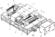
FIG. 1 is a schematic view showing the overall structure of a curved glass hot bending apparatus according to an embodiment of the present invention;
FIG. 2 is a schematic view showing the internal structure of the curved glass hot bending apparatus according to the present invention in the embodiment;
FIG. 3 is a schematic view of the overall structure of the hot bending furnace;
FIG. 4 is a schematic view of the internal structure of the hot bending furnace;
FIG. 5 is a schematic view of the vacuum pumping apparatus;
FIG. 6 is a schematic view of the structure of the inner furnace;
FIG. 7 is a schematic structural diagram of a feeding mechanism and a discharging mechanism;
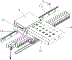
FIG. 8 is a schematic structural diagram of a feeding pushing mechanism and a discharging receiving mechanism;
FIG. 9 is a schematic diagram of the structure of a graphite mold return line;
FIG. 10 is a schematic diagram of the plasma cleaning mechanism;
the attached drawings are marked as follows: 100-workbench, 200-upper frame, 300-lower frame, 400-cooling water system, 1-hot bending furnace, 11-inner furnace, 110-inner furnace inlet, 12-outer furnace, 13-heat insulation board, 14-annular copper pipe, 15-cold water pipe, 16-temperature sensor, 2-graphite mold return line, 21-mold linear containing frame, 210-mold containing groove, 22-mold return moving component, 221-horizontal moving frame, 222-lifting frame, 2221-lifting fixture block, 223-linear guide rail, 3-feeding mechanism, 31-support, 32-horizontal linear module, 33-vertical moving component, 34-cylinder clamping jaw, 4-blanking mechanism, 5-feeding pushing mechanism, 51-guide rail linear module, 511-linear module, 512-linear guide rail, 52-material loading table, 53-material loading table pushing cylinder, 54-slider seat, 6-discharging material receiving mechanism, 7-plasma cleaning mechanism, 70-air knife mounting frame, 71-plasma air knife, 72-ion air bar, 8-vacuum suction device, 81-vacuum pump, 9-graphite mould, 91-upper mould and 92-lower mould.
Detailed Description
The technical solutions of the present invention are further described in detail below with reference to specific examples and drawings, but the scope and implementation of the present invention are not limited thereto. In the description of the embodiments of the present invention, it should be noted that the terms "upper", "lower", "front", "rear", and the like are used for distinguishing the description, and are used for convenience only to describe the present invention and to simplify the description, but do not indicate or imply that the referred devices or elements must have a specific order, be constructed in a specific order, and operate, and therefore should not be construed as limiting the present invention, nor should be construed as indicating or implying relative importance.
Referring to fig. 1-2, the curved glass hot bending apparatus of the present invention includes a workbench 100, and a hot bending furnace 1, a graphite mold return line 2, a feeding mechanism 3, a blanking mechanism 4, a feeding pushing mechanism 5, a discharging receiving mechanism 6, and a plasma cleaning mechanism 7 disposed on the workbench 100.
In a specific embodiment, the apparatus is divided into an upper frame 200 and a lower frame 300, the work table 100 is disposed on the lower frame 300, the upper frame 200 covers the work table 100, and the upper frame 200 and the lower frame 300 are fixed to form a unitary machine. Moreover, the upper machine frame 200 is provided with the window door plate and the double-sided touch screen control box, so that the pollution of external dust to the equipment can be effectively prevented, the double-sided touch screen is more in line with human engineering, and the debugging and the use of technicians are very convenient.
The feeding and pushing mechanism 5 is arranged at the inlet end of the hot bending furnace 1 and is used for pushing the graphite mold loaded with the plane glass into the hot bending furnace 1; the discharging and receiving mechanism 6 is arranged at the outlet end of the hot bending furnace 1 and is used for receiving and taking the graphite mold loaded with the formed hot bent glass and output from the hot bending furnace 1.
The feeding mechanism 3 is arranged between the outlet end of the graphite mold return line 2 and the inlet end of the hot bending furnace 1 and is used for closing the upper mold and the lower mold of the graphite mold and carrying the graphite mold after closing; and the blanking mechanism 4 is arranged between the inlet end of the graphite mold return line 2 and the outlet end of the hot bending furnace 1 and is used for separating an upper mold from a lower mold of the graphite mold and carrying the separated upper mold and the separated lower mold of the graphite mold.
The graphite mold return line 2 is used for conveying the graphite mold in a return flow mode; the plasma cleaning mechanism 7 is used for performing plasma cleaning on the graphite mold return line 2.
When the hot bending forming work of the curved glass is carried out, an upper die and a lower die of the graphite die are placed on the graphite die return line 2 and conveyed to the inlet end close to the hot bending furnace 1, wherein the upper die of the graphite die is a male die, and the lower die of the graphite die is a female die. The lower die of the graphite die is transferred to the feeding pushing mechanism 5 through the feeding mechanism 3, the planar glass to be hot-bent is transferred and placed on the lower die, the upper die is covered, and then the graphite die containing the planar glass is pushed into the hot bending furnace 1 through the feeding pushing mechanism 5 to be hot-bent and formed. After the hot bending forming is completed, the feeding pushing mechanism 5 continues to push the graphite mold to discharge from the outlet of the hot bending furnace 1, and the discharging receiving mechanism 6 receives materials. Then, the blanking mechanism 4 separates the upper mold of the graphite mold on the discharging material receiving mechanism 6 and carries the upper mold to the graphite mold return line 2 to flow back to the inlet end close to the hot bending furnace 1, the molded curved glass is taken down, and the blanking mechanism 4 continues to speak the lower mold and carries the lower mold to the graphite mold return line 2 to flow back to the inlet end close to the hot bending furnace 1.
Referring to fig. 3-4, in a preferred embodiment, the hot bending furnace 1 comprises an inner furnace 11 and an outer furnace 12; the outer furnace 12 is wrapped outside the inner furnace 11, and a heat insulation plate 13 is arranged between the inner furnace 11 and the outer furnace 12. At the curved during operation of heat, be the fashioned cavity of glass heat in the interior stove 11, can provide the high temperature that satisfies the curved demand of glass heat, and it is thermal-insulated through setting up outer stove 12 parcel and heat insulating board 13, can prevent effectively that the inside temperature of interior stove 11 from expanding outward, fabulous assurance glass's temperature balance.
An annular copper pipe 14 which is wound into turns is arranged inside the furnace body of the inner furnace 11, and the length direction of the annular copper pipe 14 is along the direction from the inlet to the outlet of the inner furnace 11; the annular copper tube 14 includes two or more tubes arranged side by side. The inner furnace 11 is externally connected with a vacuum suction device 8, and as shown in fig. 5, a vacuum pump 81 is arranged in the vacuum suction device 8; and, the inlet 110 and the outlet of the inner furnace 11 are both provided with a gate, and the gate can form a closed space in the body of the inner furnace 11 after being closed. In addition, two ends of the annular copper pipe 14 are externally connected with a high-frequency heater. And, still have mould in the interior stove 11 and bear the guide rail for bearing the graphite jig and advance, surface finish reaches Ra =0.8 mu m, can effectually avoid the graphite jig to produce the phenomenon of falling powder at the slip process.
When hot bending operation is carried out, a graphite mold containing glass to be hot bent enters the inner furnace 11 and is positioned inside the wire turn of the annular copper tube 14, the vacuum suction device 8 vacuumizes the inner furnace 11, the high-frequency heater inputs alternating current to the annular copper tube 14 according to temperature setting, the annular copper tube 14 carries out induction heating on the graphite mold positioned inside the wire turn of the annular copper tube 14, and the heated graphite mold further heats and softens the plane glass. Under the vacuum condition, the softened plane glass is bent and deformed under the action of the self gravity of the upper die of the graphite die, so that the glass is naturally hot-bent and formed.
Wherein, the high-frequency heater can generate and output 3.75KW-50KW and 500 KHz-1000 KHz high-frequency current, or generate and output 50-200KW and 20-100 KHz intermediate-frequency current. The heating and temperature rising mode of the graphite mold is controlled by controlling the high-frequency current or the medium-frequency current input by the high-frequency heater, and the temperature of the curved glass in hot bending molding is controlled.
Referring to fig. 6, in a preferred embodiment, a cold water pipe 15 is provided on the top of the inner furnace 11. Specifically, in a specific embodiment, the cold water pipe 15 is provided on an upper cover of the inner furnace 11. During hot bending operation, circulating water can be introduced into the cold water pipe 15, so that the upper cover of the inner furnace 11 is prevented from being burnt out due to overhigh temperature.
Moreover, the inner furnace 11 is further provided with a temperature sensor 16, and the temperature sensor 16 is connected with the high-frequency heater through a PLC controller. Specifically, in this particular embodiment, the temperature sensor 16 is an infrared temperature sensor.
In a specific embodiment, the inner furnace 11 is provided with a glass window; the temperature sensor 16 is arranged at the outer side of the inner furnace 11, and a probe of the temperature sensor 16 penetrates through the glass window and extends into the furnace body of the inner furnace 11, and is driven by a motor to perform adjustable accurate detection on the temperature of the graphite mold in the inner furnace 11. During the hot bending operation, the probe of the temperature sensor 16 can be extended into the furnace body of the inner furnace 11, so that the heating temperature of the graphite mold (namely the heating temperature of the glass) can be accurately detected, and the current frequency can be controlled in real time through the real-time feedback connection of the temperature sensor 16 and the high-frequency heater, thereby effectively controlling the heating temperature of the graphite mold.
In an optional embodiment, two temperature sensors 16 are arranged along the direction from the inlet to the outlet of the inner furnace 11, so that the heating condition of the graphite mold in the inner furnace 11 can be monitored in real time and intensively, the heating temperature of the graphite mold can be accurately controlled, and the production quality of hot-bent glass can be improved.
In a preferred embodiment, the inner furnace 11 includes two or more inner furnaces 11 arranged side by side, and a heat insulation plate 13 is disposed between two adjacent inner furnaces 11. More than two inner furnaces 11 are adopted for hot bending forming production of curved glass, so that the production efficiency and the productivity are greatly improved, and the large-scale production requirement of the curved glass is met.
Referring to fig. 7, in a preferred embodiment, the feeding mechanism 3 and the discharging mechanism 4 each include a bracket 31, and a horizontal linear module 32 disposed on the bracket 31; the horizontal linear module 32 is provided with a vertical moving assembly 33 in a sliding manner, and the vertical moving assembly 33 comprises a vertical driving electric cylinder and a vertical sliding block; the vertical moving assembly 33 is provided with a cylinder clamping jaw 34 in a sliding manner, and specifically, the cylinder clamping jaw 34 is arranged on a vertical sliding block of the vertical moving assembly 33.
When the feeding mechanism 3 performs feeding work or the discharging mechanism 4 performs discharging work, the cylinder clamping jaw 34 is used for grabbing a lower die or an upper die of the graphite die, and then the horizontal linear module 32 and the vertical moving assembly 33 are used for realizing space transfer in the horizontal and vertical directions.
Referring to fig. 8, in the preferred embodiment, the feeding pushing mechanism 5 and the discharging receiving mechanism 6 each include a guide rail linear module 51, a loading platform 52 and a loading platform pushing cylinder 53. The material loading platform 52 and the material loading platform pushing cylinder 53 are slidably arranged on the guide rail linear module 51 through the slider seat 54, the guide rail linear module 51 comprises a linear module 511 and a linear guide rail 512, the linear guide rail 512 is arranged in parallel with the linear module 511, one end of the material loading platform 52 is driven by the linear module 511 to be slidably arranged on the linear module 511, and the other end of the material loading platform is slidably arranged on the linear guide rail 512, so that the material loading platform 52 can slide more stably. The output end of the material loading platform pushing cylinder 53 is in transmission connection with the material loading platform 52, the material loading platform 52 is used for loading a graphite mold, and the material loading platform pushing cylinder 53 can push the material loading platform 52 to be close to the inlet or the outlet of the hot bending furnace 1 for feeding or receiving materials.
In a specific embodiment, one end of the guide rail linear module 51 of the feeding pushing mechanism 5 extends to the feeding mechanism 3, and the other end extends to the inlet of the hot bending furnace 1, so that the feeding pushing mechanism 5 can conveniently place the upper die and the lower die of the graphite die on the material loading table 52 of the feeding pushing mechanism 5 for die assembly, and then the graphite die is transported to the inlet of the hot bending furnace 1 by the guide rail linear module 51 for feeding; one end of the guide rail linear module 51 of the discharging material receiving mechanism 6 extends to the discharging mechanism 4, the other end of the guide rail linear module 51 of the discharging material receiving mechanism 6 extends to the outlet of the hot bending furnace 1, the graphite mold is transported to the discharging mechanism 4 from the outlet of the hot bending furnace 1 to be discharged during discharging, and the upper mold and the lower mold of the graphite mold are conveniently separated from the material carrying table 52 of the discharging material receiving mechanism 6 by the discharging mechanism 4 and then are taken down and transferred to the graphite mold return line 2.
And, still be provided with the ejector pin and push away the material cylinder on feeding push mechanism 5, push away the material cylinder with the ejector pin all sets up on slider seat 54. When feeding is carried out, the material pushing cylinder can drive the material pushing rod to push the graphite mold on the material loading platform 52 to enter the hot bending furnace 1, and the graphite mold in the hot bending furnace 1 can be pushed to discharge from the outlet of the hot bending furnace 1. In the batch production process of the curved glass, a plurality of graphite molds can be arranged and accommodated in the hot bending furnace 1 in a production line manner, the inlet end of the hot bending furnace 1 is continuously pushed by the pushing rod to feed, and the advancing graphite mold is pushed to continuously discharge from the outlet of the hot bending furnace 1.
Referring to fig. 9, in a preferred embodiment, the graphite mold return line 2 includes a mold linear holding frame 21, and the mold linear holding frame 21 has a plurality of mold holding tanks 210 arranged linearly. During operation, the lower mould 92 and the upper mould 91 of graphite jig 9 hold the frame 21 at the mould linearity and go up the line mistake and place to make things convenient for feed mechanism 3 to snatch lower mould 92 in proper order and go up mould 91 and carry out the compound die.
Wherein, symmetrical and synchronous mold backflow moving assemblies 22 are arranged on two sides of the mold linear containing frame 21; the mold reflow movement assembly 22 includes a horizontal movement frame 221 and a lift frame 222; the horizontal moving frame 221 is slidably disposed on a linear guide rail 223, and the length direction of the linear guide rail 223 is the same as the length direction of the linear mold accommodating frame 21; the jacking frame 222 is arranged on the horizontal moving frame 221 in a vertically sliding manner, and specifically, a jacking cylinder for jacking the jacking frame 222 is arranged on the horizontal moving frame 221; a plurality of linearly arranged jacking fixture blocks 2221 are arranged on one side of the jacking frame 222 facing the linear die holding frame 21. Moreover, the distribution of the jacking latches 2221 corresponds to the distribution of the mold receiving slots 210 on the mold linear receiving rack 21 at intervals, that is, the distance between two adjacent jacking latches 2221 is equal to the distance between two adjacent mold receiving slots 210.
When the graphite mold reflow line 2 performs the reflow operation of the graphite mold, the lower mold 92 and the upper mold 91 of the graphite mold 9 separated by the blanking mechanism 4 are placed on the mold linear containing frame 21 in a linear staggered manner, the lower mold 92 is placed on the former mold containing groove 210, and the upper mold 91 is placed on the latter mold containing groove 210. When the lower die 92 and the upper die 91 at the feeding end are taken by the feeding mechanism 3, fed and matched, the subsequent lower die 92 and the subsequent upper die 91 are subjected to backflow movement, firstly, the jacking frame 222 is driven to jack upwards, the jacking fixture blocks 2221 on the jacking frame 222 are jacked and clamped on the lower die 92, so that the lower die 92 is lifted, the horizontal moving frame 221 is driven to move forwards and stop moving after crossing the position of one upper die 91, the jacking frame 222 descends, the lower die 92 is placed on the die containing groove 210 of the upper lower die 92, and the staggered movement and the advancing of the lower die 92 are completed. Then, the horizontal moving frame 221 of the mold reflow moving assembly 22 is driven to translate backward, and the mold reflow moving assembly 22 continues to complete the staggered movement advance of the upper mold 91.
Referring to fig. 10, in a preferred embodiment, the plasma cleaning mechanism 7 includes two pairs of plasma air knives 71 distributed above and below the graphite mold return line 2. The plasma air knives 71 are mounted on the air knife mounting frame 70, the air knife mounting frame 70 is a gantry frame arranged on the graphite mold return line 2, the two pairs of plasma air knives 71 are arranged above and below the graphite mold return line 2 through the air knife mounting frame 70, air outlets of the plasma air knives 71 face the graphite mold return line 2, and the plasma air knives 71 distributed up and down can blow ion air on the graphite mold return line 2 and on two surfaces of the upper die 91 and the lower die 92 of the graphite mold 9. Further, the plasma air knife 71 is provided with an ion air bar 72. So, graphite jig 9 carries out the backward flow in-process on graphite jig return line 2, and the clean mechanism 7 of plasma can effectively get rid of the dust and the static on graphite jig 9's last mould 91 and lower mould 92 surface, avoids follow-up glass because dust etc. produce bad such as concave-convex point in the hot bending forming process, improves the product yield, makes the curved surface glass quality of production excellent.
In the curved glass hot bending apparatus of the present invention, the bottom of the lower frame 300 is further provided with a cooling water system 400 for supplying cooling water for cooling the hot bending furnace 1 after the hot bending operation is completed.
The above embodiments are merely preferred embodiments of the present invention, and the technical solutions of the present invention are described in further detail, but the scope and implementation of the present invention are not limited thereto, and any changes, combinations, deletions, substitutions or modifications that do not depart from the spirit and principle of the present invention are included in the scope of the present invention.