CN211937536U - Automatic change pipe fitting paint spraying system - Google Patents
Automatic change pipe fitting paint spraying system Download PDFInfo
- Publication number
- CN211937536U CN211937536U CN202020365731.7U CN202020365731U CN211937536U CN 211937536 U CN211937536 U CN 211937536U CN 202020365731 U CN202020365731 U CN 202020365731U CN 211937536 U CN211937536 U CN 211937536U
- Authority
- CN
- China
- Prior art keywords
- fixedly connected
- motor
- machine body
- plug
- pipe fitting
- Prior art date
- Legal status (The legal status is an assumption and is not a legal conclusion. Google has not performed a legal analysis and makes no representation as to the accuracy of the status listed.)
- Expired - Fee Related
Links
- 239000003973 paint Substances 0.000 title claims abstract description 29
- 238000005507 spraying Methods 0.000 title claims abstract description 11
- 239000007921 spray Substances 0.000 claims abstract description 19
- 239000000428 dust Substances 0.000 claims abstract description 11
- 238000010422 painting Methods 0.000 claims description 8
- 239000011521 glass Substances 0.000 claims description 7
- 239000000049 pigment Substances 0.000 claims description 7
- 230000002349 favourable effect Effects 0.000 abstract description 3
- 230000009286 beneficial effect Effects 0.000 description 1
- 230000007547 defect Effects 0.000 description 1
- 238000005516 engineering process Methods 0.000 description 1
- 238000012986 modification Methods 0.000 description 1
- 230000004048 modification Effects 0.000 description 1
- 230000002035 prolonged effect Effects 0.000 description 1
- 238000007789 sealing Methods 0.000 description 1
Images


Abstract
The utility model discloses an automatic change pipe fitting paint spraying system, which comprises a bod, the first motor of top edge fixedly connected with of organism, the output shaft fixedly connected with driving gear of first motor, driving gear meshing is connected with driven gear, the first threaded spindle of driven gear fixedly connected with, and rotate between the inside wall of first threaded spindle and organism and be connected. The utility model discloses in, drive the pipe fitting through the second motor at the uniform velocity and rotate on the mounting, paint pump sprays to the pivoted pipe fitting in the paint box through flexible pipe leading-in shower nozzle after that, first motor in the dust cover passes through the driving gear and drives driven gear reciprocating rotation simultaneously, thereby it drives first threaded spindle rotation to make driven gear, and then make the carriage make a round trip to slide in spacing bottom side, so that the shower nozzle will paint and spout the surface at the pipe fitting evenly, thereby remove the step of manual adjustment from, be favorable to work efficiency's promotion.
Description
Technical Field
The utility model relates to a pipe fitting processing technology field especially relates to an automatic change pipe fitting paint spraying system.
Background
The pipe fitting is a general name of parts and components which play roles of connection, control, sealing, support and the like in a pipeline system.
At present, the existing pipe fitting paint spraying equipment needs to clamp the pipe fitting when the pipe fitting is painted, so that the part clamped on the outer surface of the pipe fitting cannot be painted at one time, the position of the pipe fitting needs to be manually readjusted in the later period, and the paint spraying efficiency of the pipe fitting is greatly reduced.
SUMMERY OF THE UTILITY MODEL
The utility model aims at solving the defects existing in the prior art and providing an automatic pipe fitting paint spraying system.
In order to achieve the above purpose, the utility model adopts the following technical scheme: an automatic pipe fitting paint spraying system comprises a machine body, wherein a first motor is fixedly connected to the edge of the top end of the machine body, an output shaft of the first motor is fixedly connected with a driving gear, the driving gear is connected with a driven gear in a meshed mode, the driven gear is fixedly connected with a first threaded shaft, the first threaded shaft is rotatably connected with the inner side wall of the machine body, the first threaded shaft is in threaded connection with a moving frame, a limiting frame is embedded into the top side of the moving frame in a sliding mode and is fixedly connected with the machine body, a spray head is fixedly connected to the bottom end of the moving frame, a telescopic pipe is fixedly connected to the top end of the spray head, a pigment pump is fixedly connected to the top end of the telescopic pipe, a paint box is fixedly connected to one side, away from the telescopic pipe, of the pigment pump is fixedly connected with the paint box, and a second motor, the output shaft fixedly connected with fixed plug of second motor just rotates between the inside wall of fixed plug and organism and is connected, one side threaded connection that fixed plug was kept away from to the inside wall of organism has the second screw thread axle, the medial extremity fixedly connected with mounting of second screw thread axle, the mounting rotates and is connected with and rotates the plug.
As a further description of the above technical solution:
the first motor, the driving gear and the driven gear are provided with a dust cover at the outer side together, and the dust cover is fixedly connected with the machine body.
As a further description of the above technical solution:
the outer side wall of the machine body is fixedly connected with a glass cover corresponding to the position of the spray head.
As a further description of the above technical solution:
the outer side wall of the machine body is rotatably connected with a machine door through a hinge corresponding to the position of the fixed plug and the position of the rotating plug, and the machine door is positioned under the glass cover.
As a further description of the above technical solution:
and one end of the second threaded shaft, which is far away from the rotating plug, is fixedly connected with a rotating head.
As a further description of the above technical solution:
the two sides of the inner bottom of the machine body are respectively fixedly connected with a first support frame and a second support frame, the first support frame is rotatably connected with an output shaft of a second motor, and the second support frame is in threaded connection with a second threaded shaft.
As a further description of the above technical solution:
the rotary plug and the fixing piece are embedded and rotatably connected with an auxiliary bearing.
The utility model discloses following beneficial effect has:
the automatic pipe painting system is characterized in that a pipe to be painted is embedded on a fixed plug, then a worker rotates a rotary head to drive a second threaded shaft to rotate on a machine body and a second support frame, so that the pipe fitting is pushed against the fixed plug by rotating the plug, and then the machine door is closed by the staff, then the second motor drives the pipe fitting to rotate on the fixing piece at a constant speed, then the paint pump leads the paint in the paint box into the spray head through the extension pipe and sprays the paint to the rotating pipe fitting through the spray head, meanwhile, a first motor in the dust cover drives a driven gear to rotate in a reciprocating manner through a driving gear, so that the driven gear drives a first threaded shaft to rotate, and then make the carriage make a round trip to slide in spacing bottom side to the shower nozzle sprays paint evenly at the surface of pipe fitting, thereby removes the step of artifical adjustment from, is favorable to work efficiency's promotion.
Drawings
Fig. 1 is a schematic view of the overall structure of the present invention;
fig. 2 is a front view of the present invention;
fig. 3 is a schematic structural view of the limiting frame and the moving frame of the present invention.
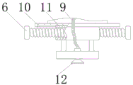
Illustration of the drawings: 1. a body; 2. a first motor; 3. a driving gear; 4. a driven gear; 5. a dust cover; 6. a first threaded shaft; 7. a paint box; 8. a paint pump; 9. a telescopic pipe; 10. a limiting frame; 11. a movable frame; 12. a spray head; 13. a second motor; 14. a first support frame; 15. fixing the plug; 16. turning the head; 17. a second threaded shaft; 18. a second support frame; 19. a fixing member; 20. rotating the plug; 21. a glass cover; 22. a machine door.
Detailed Description
The technical solutions in the embodiments of the present invention will be described clearly and completely with reference to the accompanying drawings in the embodiments of the present invention, and it is obvious that the described embodiments are only some embodiments of the present invention, not all embodiments. Based on the embodiments in the present invention, all other embodiments obtained by a person skilled in the art without creative work belong to the protection scope of the present invention.
In the description of the present invention, it should be noted that the terms "center", "upper", "lower", "left", "right", "vertical", "horizontal", "inner", "outer", and the like indicate orientations or positional relationships based on the orientations or positional relationships shown in the drawings, and are only for convenience of description and simplification of description, but do not indicate or imply that the device or element referred to must have a specific orientation, be constructed and operated in a specific orientation, and thus, should not be construed as limiting the present invention; the terms "first," "second," and "third" are used for descriptive purposes only and are not to be construed as indicating or implying relative importance, and furthermore, unless otherwise explicitly stated or limited, the terms "mounted," "connected," and "connected" are to be construed broadly and may be, for example, fixedly connected, detachably connected, or integrally connected; can be mechanically or electrically connected; they may be connected directly or indirectly through intervening media, or they may be interconnected between two elements. The specific meaning of the above terms in the present invention can be understood in specific cases to those skilled in the art.
Referring to fig. 1-3, the present invention provides an embodiment: an automatic pipe fitting paint spraying system comprises a machine body 1, a first motor 2 is fixedly connected at the edge of the top end of the machine body 1, a driving gear 3 is fixedly connected with an output shaft of the first motor 2, the driving gear 3 is connected with a driven gear 4 in a meshing manner, the driven gear 4 is fixedly connected with a first threaded shaft 6, the first threaded shaft 6 is rotatably connected with the inner side wall of the machine body 1, the first threaded shaft 6 is in threaded connection with a moving frame 11, a limiting frame 10 is embedded and slidably connected at the top side of the moving frame 11, the limiting frame 10 is fixedly connected with the machine body 1, a spray head 12 is fixedly connected at the bottom end of the moving frame 11, a telescopic pipe 9 is fixedly connected at the top end of the spray head 12, a pigment pump 8 is fixedly connected at the top end of the telescopic pipe 9, a paint box 7 is fixedly connected at one side, far away from the telescopic pipe 9, of the pigment pump 8 is fixedly, the output shaft of the second motor 13 is fixedly connected with a fixed plug 15, the fixed plug 15 is rotatably connected with the inner side wall of the machine body 1, one side, far away from the fixed plug 15, of the inner side wall of the machine body 1 is in threaded connection with a second threaded shaft 17, the inner side end of the second threaded shaft 17 is fixedly connected with a fixing piece 19, and the fixing piece 19 is rotatably connected with a rotating plug 20.
The first motor 2, the driving gear 3 and the driven gear 4 are provided with a dust cover 5 at the outer sides together, and the dust cover 5 is fixedly connected with the machine body 1, so that external dust is prevented from falling on the driving gear 3 and the driven gear 4, and the service life of the equipment is prolonged; the outer side wall of the machine body 1 is fixedly connected with a glass cover 21 corresponding to the position of the spray head 12, so that a worker can conveniently observe the paint spraying progress; the outer side wall of the machine body 1 is rotatably connected with a machine door 22 through hinges corresponding to the positions of the fixed plug 15 and the rotating plug 20, and the machine door 22 is positioned right below the glass cover 21, so that the pipe fittings can be placed and taken conveniently; one end of the second threaded shaft 17, which is far away from the rotating plug 20, is fixedly connected with a rotating head 16, so that the position of the second threaded shaft 17 can be conveniently adjusted; a first support frame 14 and a second support frame 18 are fixedly connected to two sides of the inner bottom of the machine body 1 respectively, the first support frame 14 is rotatably connected with an output shaft of the second motor 13, and the second support frame 18 is in threaded connection with the second threaded shaft 17, so that the second motor 13 and the second threaded shaft 17 can be conveniently supported, and the stability of the pipe fitting during rotation is ensured; the rotary plug 20 is embedded in the fixing member 19 and rotatably connected with an auxiliary bearing, so that the rotary plug 20 is prevented from being tightly pressed in the fixing member 19 and being incapable of rotating.
The working principle is as follows: when an automatic pipe painting system is used, a pipe to be painted is firstly embedded on a fixed plug 15, then a worker rotates a rotating head 16 to enable the rotating head 16 to drive a second threaded shaft 17 to rotate on a machine body 1 and a second supporting frame 18, so that a pipe is pressed against the fixed plug 15 by a rotating plug 20, then the worker closes a machine door 22, then the pipe is driven to rotate on a fixed piece 19 at a constant speed by a second motor 13, then paint in a paint box 7 is guided into a spray head 12 through an extension pipe 9 by a paint pump 8 and is sprayed to the rotating pipe through the spray head 12, meanwhile, a first motor 2 in a dust cover 5 drives a driven gear 4 to rotate in a reciprocating manner through a driving gear 3, so that the driven gear 4 drives a first threaded shaft 6 to rotate, and then a moving frame 11 slides back and forth at the bottom side of a limiting frame 10, so that the spray head 12 can uniformly spray the paint on the outer surface of the pipe, thereby remove the step of manual adjustment from, be favorable to work efficiency's promotion, have certain practicality.
Finally, it should be noted that: although the present invention has been described in detail with reference to the foregoing embodiments, it will be apparent to those skilled in the art that modifications and variations can be made in the embodiments or in part of the technical features of the embodiments without departing from the spirit and the principles of the present invention.
Claims (7)
1. The utility model provides an automatic change pipe fitting paint spraying system, includes organism (1), its characterized in that: the machine body is characterized in that a first motor (2) is fixedly connected to the edge of the top end of the machine body (1), an output shaft of the first motor (2) is fixedly connected with a driving gear (3), the driving gear (3) is connected with a driven gear (4) in a meshed mode, the driven gear (4) is fixedly connected with a first threaded shaft (6), the first threaded shaft (6) is rotatably connected with the inner side wall of the machine body (1), the first threaded shaft (6) is in threaded connection with a moving frame (11), a limiting frame (10) is connected to the top side of the moving frame (11) in an embedded sliding mode, the limiting frame (10) is fixedly connected with the machine body (1), a spray head (12) is fixedly connected to the bottom end of the moving frame (11), a telescopic pipe (9) is fixedly connected to the top end of the spray head (12), and a pigment pump (8), and fixed connection does not have between the top of pigment pump (8) and organism (1) one side fixedly connected with paint box (7) that flexible pipe (9) were kept away from in pigment pump (8), lateral wall bottom side fixedly connected with second motor (13) of organism (1), the output shaft fixedly connected with attach plug (15) of second motor (13), and rotate between the inside wall of attach plug (15) and organism (1) and be connected, one side threaded connection that attach plug (15) were kept away from to the inside wall of organism (1) has second threaded shaft (17), the medial extremity fixedly connected with mounting (19) of second threaded shaft (17), mounting (19) rotate and are connected with rotation plug (20).
2. An automated pipe painting system according to claim 1, wherein: the dust cover (5) is arranged on the outer sides of the first motor (2), the driving gear (3) and the driven gear (4) together, and the dust cover (5) is fixedly connected with the machine body (1).
3. An automated pipe painting system according to claim 1, wherein: the outer side wall of the machine body (1) is fixedly connected with a glass cover (21) corresponding to the position of the spray head (12).
4. An automated pipe painting system according to claim 1, wherein: the outer side wall of the machine body (1) is connected with a machine door (22) in a rotating mode through hinges corresponding to the positions of the fixed plug (15) and the rotating plug (20), and the machine door (22) is located under the glass cover (21).
5. An automated pipe painting system according to claim 1, wherein: one end, far away from the rotating plug (20), of the second threaded shaft (17) is fixedly connected with a rotating head (16).
6. An automated pipe painting system according to claim 1, wherein: the machine body (1) is characterized in that a first support frame (14) and a second support frame (18) are fixedly connected to two sides of the inner bottom of the machine body (1) respectively, the first support frame (14) is rotatably connected with an output shaft of a second motor (13), and the second support frame (18) is in threaded connection with a second threaded shaft (17).
7. An automated pipe painting system according to claim 1, wherein: the rotary plug (20) and the fixing piece (19) are embedded and rotatably connected with an auxiliary bearing.
Priority Applications (1)
| Application Number | Priority Date | Filing Date | Title |
|---|---|---|---|
| CN202020365731.7U CN211937536U (en) | 2020-03-21 | 2020-03-21 | Automatic change pipe fitting paint spraying system |
Applications Claiming Priority (1)
| Application Number | Priority Date | Filing Date | Title |
|---|---|---|---|
| CN202020365731.7U CN211937536U (en) | 2020-03-21 | 2020-03-21 | Automatic change pipe fitting paint spraying system |
Publications (1)
| Publication Number | Publication Date |
|---|---|
| CN211937536U true CN211937536U (en) | 2020-11-17 |
Family
ID=73179011
Family Applications (1)
| Application Number | Title | Priority Date | Filing Date |
|---|---|---|---|
| CN202020365731.7U Expired - Fee Related CN211937536U (en) | 2020-03-21 | 2020-03-21 | Automatic change pipe fitting paint spraying system |
Country Status (1)
| Country | Link |
|---|---|
| CN (1) | CN211937536U (en) |
-
2020
- 2020-03-21 CN CN202020365731.7U patent/CN211937536U/en not_active Expired - Fee Related
Similar Documents
| Publication | Publication Date | Title |
|---|---|---|
| CN203783086U (en) | Interior painting robot | |
| CN107535322B (en) | Urban afforestation is with automatic control equipment of irritating that spouts | |
| CN211849210U (en) | Highway is with removing raise dust device fast | |
| CN211937536U (en) | Automatic change pipe fitting paint spraying system | |
| CN213391048U (en) | Wall application device for engineering construction | |
| CN211114663U (en) | Architectural decoration spraying device | |
| CN218360045U (en) | Water-based paint spraying equipment capable of automatically adjusting spraying direction | |
| CN216273789U (en) | Glass frosting processing equipment | |
| CN211838725U (en) | Automotive interior spare spraying device | |
| CN212041129U (en) | Processing equipment for slender shaft of electric submersible pump | |
| CN210474437U (en) | Paint spraying apparatus for automobile production | |
| CN218796786U (en) | Spraying device is used in processing of PVC coated fabric | |
| CN214262434U (en) | Paint spraying device for automobile finish paint | |
| CN220440529U (en) | Flat wire motor stator paint-dripping gluing equipment | |
| CN219723274U (en) | Spraying device for processing solid wood furniture | |
| CN220736868U (en) | Building site sprays dust device | |
| CN209362751U (en) | It is capable of the ultra low volume sprayer of auto-changing angle | |
| CN219219690U (en) | Automatic wall brushing device for interior decoration | |
| CN219424705U (en) | Metal surface coating sprayer | |
| CN219073296U (en) | Door plant paint spraying apparatus | |
| CN214160315U (en) | LCD glass adhesive deposite device | |
| CN214183715U (en) | Spraying device for aluminum profile production | |
| CN212943621U (en) | Coating spraying device is used in door valve production | |
| CN220008146U (en) | Gluing equipment for wood processing | |
| CN211514995U (en) | Spraying device for corrosion prevention of metal products |
Legal Events
| Date | Code | Title | Description |
|---|---|---|---|
| GR01 | Patent grant | ||
| GR01 | Patent grant | ||
| CF01 | Termination of patent right due to non-payment of annual fee |
Granted publication date: 20201117 |
|
| CF01 | Termination of patent right due to non-payment of annual fee |