CN211912056U - Multifunctional nursing table for sickbed - Google Patents
Multifunctional nursing table for sickbed Download PDFInfo
- Publication number
- CN211912056U CN211912056U CN201922366042.8U CN201922366042U CN211912056U CN 211912056 U CN211912056 U CN 211912056U CN 201922366042 U CN201922366042 U CN 201922366042U CN 211912056 U CN211912056 U CN 211912056U
- Authority
- CN
- China
- Prior art keywords
- face
- plate
- top end
- supporting plate
- nursing table
- Prior art date
- Legal status (The legal status is an assumption and is not a legal conclusion. Google has not performed a legal analysis and makes no representation as to the accuracy of the status listed.)
- Expired - Fee Related
Links
Images


Landscapes
- Invalid Beds And Related Equipment (AREA)
Abstract
The utility model discloses a multifunctional nursing table for sickbeds, which comprises support legs and a fixing screw rod, the utility model is provided with a support mechanism outside the table plate, by starting the electric motor, the electric motor drives the turntable to rotate, and simultaneously the hollow plate is driven by the fixed cylinder to push the push plate to vertically move, the push plate drives the supporting plate to rotate to form a certain included angle with the table plate, and books or electronic equipment are placed between the supporting plate and the supporting plate, so that the books or electronic equipment are quickly and stably supported, the beneficial effects of more patients are met, the fixing mechanism is arranged on the guide plate, then the T-shaped rod is pushed downwards, so that the T-shaped rod drives the fixing block and the pressing plate to move downwards to be tightly attached to the top end surface of the silicon sheet, simultaneously the fixed block promotes to fix the fixed block after the sheetmetal takes place to deform, has reached and is convenient for carry out quick fixed beneficial effect when wholly moving nursing table.
Description
Technical Field
The utility model relates to a nursing table correlation field specifically is a multi-functional nursing table that sick bed was used.
Background
As the name suggests, a nursing table is specially used for patients in hospitals, and the daily life of the patients who lie in bed for a long time or need to lie in bed due to surgical operations needs to be carried out on the sick bed, so that a table for the daily life of the patients is needed.
When the nursing table is used, because the function of nursing table is comparatively single, some better patients of state of an illness are when wanting to go on the sick bed to read or use electronic equipment, because the desktop is relatively flat, be difficult to satisfy this type of patient's demand, when the nursing table is installed on the sick bed simultaneously, be difficult to adjust through the bolt installation, and place stability lower again with gliding mode, bring inconvenience for work.
SUMMERY OF THE UTILITY MODEL
Therefore, in order to solve the above-mentioned insufficiency, the utility model provides a multifunctional nursing table for a hospital bed.
The utility model is realized in such a way, a multifunctional nursing table for sickbeds is constructed, the device comprises support legs, a fixed screw, a supporting mechanism and a fixing mechanism, the support legs are symmetrically locked at the middle parts of the left and right ends of the bottom end surface of the table plate, the inner sides of the support legs movably extend into a sliding rod, the fixed screw passes through the side surface of the support legs and then is in threaded connection with the inner side of a screw hole formed on the side surface of the sliding rod, the sliding rod is welded at the middle part of the top end surface of a guide plate, the guide plate is slidably arranged at the outer side of the guide rail, the supporting mechanism is arranged at the outer side of the table plate, the fixing mechanism is arranged at the top of the guide plate, the supporting mechanism comprises an electric motor, a shell, a rotary table, a fixed cylinder, a hollow plate, a rotating block, a push plate, a U-shaped plate, a, the fixing cylinder is arranged at the edge of the rear end face of the turntable in an integrated structure, the fixing cylinder movably extends into the inner side of the hollow plate, the left end of the outer side of the hollow plate is hinged to the inner side of an opening formed in the middle lower part of the right end face of the push plate, the middle part of the front end face of the rotating block is rotationally connected with the front end of the inner side of the shell through a rotating shaft, the upper end face and the lower end face of the rotating block are attached to the upper end face and the lower end face of the inner side of the hollow plate, the push plate is slidably mounted at the left end of the inner side of the shell and penetrates through the inner sides of square holes formed in the left end face of the inner side of the shell and the middle part of the bottom end face of the table plate, the U-shaped plate is locked at the front end of the top end face of the supporting plate, the inner side of the U-shaped plate, the power cord passes through the shell outside and then is connected with the power input end of the electric motor, and the power cord is electrically connected with the electric motor.
Preferably, fixed establishment comprises urceolus, T type pole, silica gel piece, the lantern ring, spring, fixed block, sheetmetal and clamp plate, the urceolus closure is in deflector top end face, T type pole passes urceolus top end face middle part back and is connected with clamp plate top end face middle part rotation, the silica gel piece is pasted in guide rail top end face, lantern ring activity nestification is upper end in the T type pole outside, spring both ends respectively fixed connection in lantern ring top end face and urceolus inboard top end face, and spring medial surface and T type pole side surface swing joint, the fixed block symmetry fastening has two in the middle and lower part in both ends about the T type pole, the sheetmetal is installed two in both ends middle parts about the urceolus inboard, and the sheetmetal laminates in fixed block top end face, the clamp plate passes and hugs closely in silica gel piece top end face behind the guide rail top end face.
Preferably, the length of the fixing cylinder is consistent with the thickness of the hollow plate, and the outer diameter of the fixing cylinder corresponds to the inner width of the hollow plate.
Preferably, the vertical distance between the top end face of the push plate and the top end face of the inner side of the U-shaped plate is 0.5cm, and the outer side end face of the push plate is smooth and burr-free.
Preferably, the length of the supporting plate is four fifths of the length of the supporting plate, and the top end face of the supporting plate is flush with the top end face of the supporting plate.
Preferably, the left end face and the right end face of the supporting plate are adhered with a layer of anti-skid rubber sheet, and the thickness of the rubber sheet is 0.1 cm.
Preferably, the right end face of the metal sheet is hinged with the right end face of the inner side of the outer barrel at an angle of 45 degrees, and the bottom of the metal sheet extends outwards horizontally.
Preferably, concave-convex stripes are arranged on the top end face of the silica gel sheet and the bottom end face of the pressing plate, and the concave-convex stripes horizontally extend in a left-right square shape.
Preferably, the electric motor is a 10PM10 electric motor.
Preferably, the metal sheet is made of stainless steel.
The utility model has the advantages of as follows: the utility model discloses an improve and provide a multi-functional nursing table that sick bed was used here, compare with the equipment of the same type, have following improvement:
the method has the advantages that: a multi-functional nursing table that sick bed was used, the utility model discloses a supporting mechanism has been set up outside the table, through starting electric motor for electric motor drives the carousel and rotates, the carousel drives the stationary cylinder who is connected simultaneously and rotates, cavity board promotes the push pedal vertical migration in stationary cylinder's drive simultaneously, and the push pedal drives the backup pad and rotates and form certain contained angle with the table, then rotate the layer board laminating on the table, and place books or electronic equipment between layer board and backup pad, reached and carried out the stable support with books or electronic equipment fast, satisfy more patients' beneficial effect.
The advantages are two: a multi-functional nursing table that sick bed was used, the utility model discloses a set up fixed establishment on the deflector, through carrying out horizontal migration with the deflector on the guide rail, then promote T type pole downwards for T type pole drives fixed block and clamp plate downstream and hugs closely on the top face of silica gel piece, fixes the fixed block after the fixed block promotes the sheetmetal to take place deformation simultaneously, has reached and is convenient for carry out quick fixed beneficial effect when wholly moving nursing table.
Drawings
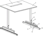
FIG. 1 is a schematic structural view of the present invention;
FIG. 2 is a front sectional view of the supporting mechanism of the present invention;
FIG. 3 is a schematic view of the connection structure of the supporting plate of the present invention;
fig. 4 is an enlarged schematic view of the structure at a in fig. 1 of the present invention;
fig. 5 is a schematic view of the front sectional structure of the fixing mechanism of the present invention.
Wherein: the device comprises a supporting leg-1, a fixed screw-2, a table plate-3, a sliding rod-4, a guide plate-5, a guide rail-6, a supporting mechanism-7, a fixing mechanism-8, an electric motor-71, a shell-72, a rotary disc-73, a fixed cylinder-74, a hollow plate-75, a rotary block-76, a push plate-77, a U-shaped plate-78, a supporting plate-79, a supporting plate-710, a power line-711, an outer cylinder-81, a T-shaped rod-82, a silica gel sheet-83, a lantern ring-84, a spring-85, a fixed block-86, a metal sheet-87 and a pressing plate-88.
Detailed Description
The present invention will be described in detail with reference to the accompanying fig. 1-5, and the technical solutions in the embodiments of the present invention will be clearly and completely described, and it is obvious that the described embodiments are only some embodiments of the present invention, not all embodiments. Based on the embodiments in the present invention, all other embodiments obtained by a person skilled in the art without creative work belong to the protection scope of the present invention.
The utility model provides a multifunctional nursing table for sickbed through improvement, which comprises a support leg 1, a fixed screw 2, a supporting mechanism 7 and a fixing mechanism 8, wherein the support leg 1 is symmetrically locked with two middle parts at the left and right ends of the bottom end surface of a table plate 3, the inner side of the support leg 1 movably extends into a sliding rod 4, the fixed screw 2 passes through the side surface of the support leg 1 and then is in threaded connection with the inner side of a screw hole formed on the side surface of the sliding rod 4, the sliding rod 4 is welded at the middle part of the top end surface of a guide plate 5, the guide plate 5 is slidably arranged at the outer side of a guide rail 6, the supporting mechanism 7 is arranged at the outer side of the table plate 3, the fixing mechanism 8 is arranged at the top of the guide plate 5, the supporting mechanism 7 is composed of an electric motor 71, a shell 72, a turntable 73, a fixed cylinder 74, a hollow plate 75, a rotating block 76, the output shaft at the rear end of the electric motor 71 is fastened on the inner ring of the turntable 73, the fixed cylinder 74 is arranged at the edge of the rear end face of the turntable 73 in an integrated structure, the fixed cylinder 74 movably extends into the inner side of the hollow plate 75, the left end of the outer side of the hollow plate 75 is hinged to the inner side of an opening formed in the middle lower part of the right end face of the push plate 77, the middle part of the front end face of the rotating block 76 is rotatably connected with the front end of the inner side of the shell 72 through a rotating shaft, the upper end face and the lower end face of the rotating block 76 are attached to the upper end face and the lower end face of the inner side of the hollow plate 75, so that the hollow plate 75 stably rotates, the push plate 77 is slidably arranged at the left end of the inner side of the shell 72, the push plate 77 penetrates through the left end of the top end face of the inner side of the shell 72 and the inner side of a square hole formed in the middle part of the bottom end face, the front parts of the left end and the right end of the supporting plate 710 are rotatably connected with the inner side of a square groove formed in the front end of the top end face of the supporting plate 79 through a rotating shaft, so that external articles can be supported conveniently, the power line 711 penetrates through the outer side of the shell 72 and then is connected to the power supply input end of the electric motor 71, and the power line 711 is electrically connected with the electric motor 71.
Further, the fixing mechanism 8 is composed of an outer cylinder 81, a T-shaped rod 82, a silicon sheet 83, a sleeve ring 84, a spring 85, a fixing block 86, a metal sheet 87 and a pressing plate 88, the outer cylinder 81 is locked on the top end face of the guide plate 5, the T-shaped rod 82 penetrates through the middle of the top end face of the outer cylinder 81 and then is rotatably connected with the middle of the top end face of the pressing plate 88, the silicon sheet 83 is pasted on the top end face of the guide rail 6, the sleeve ring 84 is movably nested at the middle upper end of the outer side of the T-shaped rod 82, two ends of the spring 85 are respectively and fixedly connected to the top end face of the sleeve ring 84 and the top end face of the inner side of the outer cylinder 81, the T-shaped rod 82 is convenient to rapidly reset, the inner side end face of the spring 85 is movably connected with the side surface of the T-shaped rod 82, the fixing block 86 is symmetrically fastened with two, the pressing plate 88 penetrates through the top end face of the guide rail 6 and then is tightly attached to the top end face of the silicon sheet 83, so that the pressing plate 88 is stably tightly attached to the guide rail 6.
Further, the length of the fixing cylinder 74 is consistent with the thickness of the hollow plate 75, and the outer diameter of the fixing cylinder 74 corresponds to the inner width of the hollow plate 75, so that the fixing cylinder 74 rapidly drives the hollow plate 75 to rotate.
Furthermore, the vertical distance between the top end surface of the push plate 77 and the top end surface of the inner side of the U-shaped plate 78 is 0.5cm, and the outer end surface of the push plate 77 is smooth and burr-free, so that the push plate 77 can stably rotate conveniently.
Further, the length of the supporting plate 710 is four fifths of the length of the supporting plate 79, and the top end face of the supporting plate 710 is flush with the top end face of the supporting plate 79, so that the supporting of the article is more stable.
Furthermore, a layer of anti-slip rubber sheet is adhered to the left and right end faces of the support plate 79, and the thickness of the rubber sheet is 0.1cm, so that the support plate 79 is prevented from sliding.
Furthermore, the right end face of the metal sheet 87 is hinged to the right end face of the inner side of the outer cylinder 81 at an angle of 45 degrees, and the bottom of the metal sheet 87 extends horizontally outwards, so that the metal sheet 87 is convenient to deform under pressure.
Furthermore, concave-convex stripes are arranged on the top end surface of the silica gel sheet 83 and the bottom end surface of the pressing plate 88, and the concave-convex stripes horizontally extend in a left-right square shape, so that the pressing plate 88 is more stably attached to the silica gel sheet 83.
Further, the electric motor 71 is a 10PM10 electric motor, and has a good self-locking function.
Furthermore, the metal sheet 87 is made of stainless steel, so that the metal sheet is not easy to rust and corrode and has a longer service life.
The utility model provides a multifunctional nursing table for a sickbed through improvement, which has the following working principle;
firstly, a guide rail 6 is installed at a designated position on two sides of a sickbed, then the nursing table is integrally installed on the sickbed in a sliding manner through a guide plate 5, the guide plate 5 horizontally moves on the guide rail 6, after the guide plate 5 moves to the designated position on the guide rail 6, a T-shaped rod 82 can be pushed downwards, so that the T-shaped rod 82 drives a fixing block 86 and a pressing plate 88 to move downwards to be attached to the top end face of a silicon sheet 83, at the moment, a spring 85 is stressed and stretched, meanwhile, the fixing block 86 pushes a metal sheet 87 to deform in the downward movement process, and after the fixing block 86 completely enters the bottom end face of the metal sheet 87, the metal sheet 87 restores elasticity to fix the fixing block 86;
secondly, the power cord 711 is then connected to the external controller, while allowing the external controller to be mounted on the patient's bed at a location convenient for the patient to use;
thirdly, the electric motor 71 is started through an external controller, so that the electric motor 71 drives the turntable 73 to rotate, the turntable 73 drives the connected fixed cylinder 74 to rotate, the hollow plate 75 is driven by the fixed cylinder 74 to push the push plate 77 to vertically move, the push plate 77 drives the support plate 79 to rotate to form a certain included angle with the table plate 3, then the support plate 710 is rotated to be attached to the table plate 3, and books or electronic equipment are placed between the support plate 710 and the support plate 79 for use;
fourthly, the support leg 1 can slide outside the sliding rod 4 by moving up and down, and after the support leg 1 moves to a proper height, the support leg can enter the corresponding screw hole on the sliding rod 4 through the fixing screw rod 2 to be fixed.
The utility model provides a multifunctional nursing table for hospital bed through improvement, the electric motor 71 is started through an external controller, the electric motor 71 drives the turntable 73 to rotate, the turntable 73 drives the connected fixed cylinder 74 to rotate, the hollow plate 75 is driven by the fixed cylinder 74 to push the push plate 77 to move vertically, the push plate 77 drives the support plate 79 to rotate to form a certain included angle with the table plate 3, then the support plate 710 is rotated to be attached on the table plate 3, and books or electronic equipment are placed between the support plate 710 and the support plate 79 to be used, thereby achieving the purpose of rapidly and stably supporting the books or electronic equipment, satisfying the beneficial effects of more patients, the T-shaped rod 82 is pushed downwards, the T-shaped rod 82 drives the fixed block 86 and the press plate 88 to move downwards to be attached to the top end surface of the silica gel sheet 83, at the moment, the spring 85 is stressed and stretched, meanwhile, the fixing block 86 pushes the metal sheet 87 to deform in the downward moving process, and after the fixing block 86 completely enters the bottom end face of the metal sheet 87, the metal sheet 87 recovers elasticity to fix the fixing block 86, so that the beneficial effect of conveniently moving the whole nursing table and simultaneously quickly fixing the nursing table is achieved.
The basic principle and the main characteristics of the utility model and the advantages of the utility model have been shown and described above, and the utility model discloses the standard part that uses all can purchase from the market, and dysmorphism piece all can be customized according to the record of the description with the drawing, and the concrete connection mode of each part all adopts conventional means such as ripe bolt rivet among the prior art, welding, and machinery, part and equipment all adopt prior art, conventional model, and conventional connection mode in the prior art is adopted in addition to circuit connection, and the details are not repeated here.
The previous description of the disclosed embodiments is provided to enable any person skilled in the art to make or use the present invention. Various modifications to these embodiments will be readily apparent to those skilled in the art, and the generic principles defined herein may be applied to other embodiments without departing from the spirit or scope of the invention. Thus, the present invention is not intended to be limited to the embodiments shown herein but is to be accorded the widest scope consistent with the principles and novel features disclosed herein.
Claims (8)
1. A multifunctional nursing table for a hospital bed comprises support legs (1) and fixing screw rods (2), wherein the support legs (1) are symmetrically locked in the middle of the left end and the right end of the bottom end surface of a table plate (3), the inner sides of the support legs (1) movably extend into sliding rods (4), the fixing screw rods (2) penetrate through the side surfaces of the support legs (1) and then are in threaded connection with the inner sides of screw holes formed in the side surfaces of the sliding rods (4), the sliding rods (4) are welded in the middle of the top end surface of a guide plate (5), and the guide plate (5) is slidably mounted on the outer side of a guide rail (6);
the method is characterized in that: the table is characterized by further comprising a supporting mechanism (7) and a fixing mechanism (8), the supporting mechanism (7) is arranged on the outer side of the table plate (3), the fixing mechanism (8) is arranged on the top of the guide plate (5), the supporting mechanism (7) is composed of an electric motor (71), a shell (72), a rotary disc (73), a fixed cylinder (74), a hollow plate (75), a rotating block (76), a push plate (77), a U-shaped plate (78), a supporting plate (79), a supporting plate (710) and a power line (711), the electric motor (71) is arranged at the front end of the bottom of the inner side of the shell (72), an output shaft of the rear end of the electric motor (71) is fastened on the inner ring of the rotary disc (73), the fixed cylinder (74) is arranged at the edge of the rear end face of the rotary disc (73) in an integrated structure, the fixed cylinder (74) movably extends into the inner side of the hollow plate (75), the left end of the outer side of the hollow plate, the middle part of the front end face of the rotating block (76) is rotatably connected with the front end of the inner side of the shell (72) through a rotating shaft, the upper end face and the lower end face of the rotating block (76) are attached to the upper end face and the lower end face of the inner side of the hollow plate (75), the push plate (77) is slidably mounted at the left end of the inner side of the shell (72), the push plate (77) penetrates through the left end face of the inner side of the shell (72) and the inner side of a square hole formed in the middle part of the bottom end face of the table plate (3), the U-shaped plate (78) is locked at the front end of the top end face of the supporting plate (79), the inner side of the U-shaped plate (78) is hinged to the top end of the outer side of the push plate (77), the front end of the left end and the right end of the supporting plate (79) is rotatably connected with the inner side of a groove formed in the rear end of the top end face of the supporting plate (79) through, the power cord (711) is electrically connected to the electric motor (71).
2. The multifunctional nursing table for hospital bed according to claim 1, wherein: the fixing mechanism (8) is composed of an outer barrel (81), a T-shaped rod (82), a silica gel sheet (83), a sleeve ring (84), a spring (85), a fixing block (86), a metal sheet (87) and a pressing plate (88), the outer barrel (81) is locked on the top end face of the guide plate (5), the T-shaped rod (82) penetrates through the middle of the top end face of the outer barrel (81) and then is rotatably connected with the middle of the top end face of the pressing plate (88), the silica gel sheet (83) is pasted on the top end face of the guide rail (6), the sleeve ring (84) is movably nested at the middle upper end of the outer side of the T-shaped rod (82), two ends of the spring (85) are respectively and fixedly connected to the top end face of the sleeve ring (84) and the inner side end face of the outer barrel (81), the inner side end face of the spring (85) is movably connected with the side surface of the T-shaped rod (82), the fixing block (86) is symmetrically fastened with two middle lower parts, and the metal sheet (87) is attached to the top end face of the fixing block (86), and the pressing plate (88) passes through the top end face of the guide rail (6) and then is attached to the top end face of the silica gel sheet (83).
3. The multifunctional nursing table for hospital bed according to claim 1, wherein: the length of the fixed cylinder (74) is consistent with the thickness of the hollow plate (75), and the outer diameter of the fixed cylinder (74) corresponds to the inner width of the hollow plate (75).
4. The multifunctional nursing table for hospital bed according to claim 1, wherein: the vertical distance between the top end face of the push plate (77) and the top end face of the inner side of the U-shaped plate (78) is 0.5cm, and the outer side end face of the push plate (77) is smooth and burr-free.
5. The multifunctional nursing table for hospital bed according to claim 1, wherein: the length of the supporting plate (710) is four fifths of the length of the supporting plate (79), and the top end face of the supporting plate (710) is flush with the top end face of the supporting plate (79).
6. The multifunctional nursing table for hospital bed according to claim 1, wherein: a layer of anti-skid rubber sheet is adhered to the left end face and the right end face of the supporting plate (79), and the thickness of the rubber sheet is 0.1 cm.
7. A multifunctional nursing table for hospital beds according to claim 2, characterized in that: the right end face of the metal sheet (87) is hinged with the right end face of the inner side of the outer barrel (81) at an angle of 45 degrees, and the bottom of the metal sheet (87) extends outwards horizontally.
8. A multifunctional nursing table for hospital beds according to claim 2, characterized in that: concave-convex stripes are arranged on the top end face of the silica gel sheet (83) and the bottom end face of the pressing plate (88), and the concave-convex stripes are horizontally extended in a left-right square shape.
Priority Applications (1)
| Application Number | Priority Date | Filing Date | Title |
|---|---|---|---|
| CN201922366042.8U CN211912056U (en) | 2019-12-25 | 2019-12-25 | Multifunctional nursing table for sickbed |
Applications Claiming Priority (1)
| Application Number | Priority Date | Filing Date | Title |
|---|---|---|---|
| CN201922366042.8U CN211912056U (en) | 2019-12-25 | 2019-12-25 | Multifunctional nursing table for sickbed |
Publications (1)
| Publication Number | Publication Date |
|---|---|
| CN211912056U true CN211912056U (en) | 2020-11-13 |
Family
ID=73326239
Family Applications (1)
| Application Number | Title | Priority Date | Filing Date |
|---|---|---|---|
| CN201922366042.8U Expired - Fee Related CN211912056U (en) | 2019-12-25 | 2019-12-25 | Multifunctional nursing table for sickbed |
Country Status (1)
| Country | Link |
|---|---|
| CN (1) | CN211912056U (en) |
Cited By (1)
| Publication number | Priority date | Publication date | Assignee | Title |
|---|---|---|---|---|
| CN115154131A (en) * | 2022-08-04 | 2022-10-11 | 新疆维吾尔自治区人民医院 | Gynaecology uses medical care frame |
-
2019
- 2019-12-25 CN CN201922366042.8U patent/CN211912056U/en not_active Expired - Fee Related
Cited By (1)
| Publication number | Priority date | Publication date | Assignee | Title |
|---|---|---|---|---|
| CN115154131A (en) * | 2022-08-04 | 2022-10-11 | 新疆维吾尔自治区人民医院 | Gynaecology uses medical care frame |
Similar Documents
| Publication | Publication Date | Title |
|---|---|---|
| CN211912056U (en) | Multifunctional nursing table for sickbed | |
| CN201267282Y (en) | Multifunctional ergonomic computer table | |
| CN202724163U (en) | Nursing chair bed | |
| CN209966851U (en) | Cardiothoracic surgery is with nursing auxiliary device | |
| CN215128799U (en) | ECG monitor fixer | |
| CN208405248U (en) | Electronic gynecological examining table | |
| CN216168494U (en) | Supporting device capable of being adjusted at multiple angles and used for general nursing | |
| CN210203980U (en) | Over-and-under type bedside cupboard with air purification function | |
| CN211409894U (en) | Dressing change frame for orthopedics department | |
| CN211704030U (en) | Multifunctional tea table, corner table and bedside cabinet structure | |
| CN211397408U (en) | Stretchable board ladder for buildings | |
| CN102563306A (en) | Grounded movable type television support | |
| CN105943134A (en) | Semi-automatic uterine manipulator | |
| CN217548457U (en) | Adjustable tray rack for medical care | |
| CN213989704U (en) | Power cabinet convenient to maintenance | |
| CN213665845U (en) | Automatic pedal stool | |
| CN212724635U (en) | Medical information service platform | |
| CN207462256U (en) | It is a kind of can stool and urine sick bed | |
| CN214806470U (en) | Support frame for shaping burned lower limbs | |
| CN211632230U (en) | A support for art design board | |
| CN212782696U (en) | Stable supporting mechanism capable of being vertically adjusted for electronic piano | |
| CN209996642U (en) | paralytic patients nursing bed | |
| CN211324013U (en) | Mattress supporting element | |
| CN211187888U (en) | Clinical care is with supplementary device of getting up | |
| CN217611788U (en) | A kind of bed for helping the old man to get up and get off the bed |
Legal Events
| Date | Code | Title | Description |
|---|---|---|---|
| GR01 | Patent grant | ||
| GR01 | Patent grant | ||
| CF01 | Termination of patent right due to non-payment of annual fee |
Granted publication date: 20201113 Termination date: 20211225 |
|
| CF01 | Termination of patent right due to non-payment of annual fee |