CN211891969U - Thermoplastic pipe device is worn to establish at long reinforcing bar periphery interval - Google Patents
Thermoplastic pipe device is worn to establish at long reinforcing bar periphery interval Download PDFInfo
- Publication number
- CN211891969U CN211891969U CN201821200478.9U CN201821200478U CN211891969U CN 211891969 U CN211891969 U CN 211891969U CN 201821200478 U CN201821200478 U CN 201821200478U CN 211891969 U CN211891969 U CN 211891969U
- Authority
- CN
- China
- Prior art keywords
- thermoplastic pipe
- thermoplastic
- reinforcing bar
- steel bar
- pipe
- Prior art date
- Legal status (The legal status is an assumption and is not a legal conclusion. Google has not performed a legal analysis and makes no representation as to the accuracy of the status listed.)
- Active
Links
Images


Abstract
A device for penetrating thermoplastic pipes at intervals on the periphery of a long steel bar belongs to the field of high-speed rails and comprises a controller, a vibration hopper and a steel bar feeding machine, the vibrating hopper and the steel bar feeding machine are respectively arranged at two ends of the equipment, a thermoplastic pipe identification device and a thermoplastic pipe carrying device are sequentially arranged behind the vibrating hopper, a thermoplastic pipe arranging groove is arranged below the thermoplastic pipe carrying device, a heating device is arranged in the thermoplastic pipe arranging groove, a steel bar moving roller is arranged at one end of the thermoplastic pipe arranging groove, a steel bar feeding machine is arranged at the other end of the thermoplastic pipe arranging groove, the steel bar feeding machine enables the steel bar to move along the thermoplastic pipe arranging groove to penetrate into the thermoplastic pipe, the thermoplastic pipe shrinks after being heated by the heating device, the equipment automatically conducts the penetration and the heating shrinkage of the thermoplastic pipe, the method can improve the setting efficiency of the steel bar insulating layer, reduce the labor intensity of workers and eliminate the eddy current generated when a train passes through the ballastless track.
Description
Technical Field
The utility model relates to a thermoplastic pipe device is worn to establish at the interval, in particular to thermoplastic pipe device is worn to establish at long reinforcing bar periphery interval belongs to the high-speed railway field.
Background
The ballastless track is a track structure which adopts integral foundations such as concrete, asphalt mixture and the like to replace a loose gravel track bed, is also called as a ballastless track, and is an advanced track technology in the world today.
The ballastless track consists of steel rails, fasteners and unit plates and has the functions of shock absorption and pressure reduction. The sleeper of the ballastless track is formed by pouring concrete, the roadbed does not need broken stones, and the steel rails and the sleeper are directly paved on the concrete road. The ballastless track is an advanced track technology in the world, can reduce maintenance, reduce dust and beautify the environment, and the speed per hour of a train can reach more than 300 kilometers.
The ballastless track engineering quality control point mainly comprises precision control, steel bar insulation and concrete crack control, wherein the effectiveness of steel bar insulation treatment and the quality of insulation quality directly influence the transmission performance of a track circuit and the stability after the track circuit is put into use. The roadbed slab is made of concrete and generally needs to be cast in situ, reinforcing steel bars are divided into one grounding unit every 100m, the longitudinal reinforcing steel bars are made of phi 18 or phi 20 deformed steel bars, and the transverse reinforcing steel bars are made of phi 16 deformed steel bars. Because the high-speed railway is direct current traction, in order to avoid the high-speed train from generating eddy current in the running process, stray current from influencing the running of the train is avoided, the transmission distance of a direct current circuit is increased, and ballastless track reinforcing steel bars need to adopt certain insulation measures. Except that two longitudinal reinforcements on two sides of the upper layer in each unit are welded and connected, all the lap joints and cross points of the other reinforcements are subjected to insulation binding treatment. The insulating quality of any two steel bars except the grounding steel bars should be not less than 2M omega. The quality control of the steel bar insulation is a key link of a ballastless track, and the quality of the insulation directly influences the transmission of a direct current circuit and the stability of a passenger special line system in future operation.
In the process of wearing to establish at actual insulating tube, because there are many crossing positions on the reinforcing bar, consequently need set up a plurality of thermoplastic pipes on a reinforcing bar, wear to establish thermoplastic pipe on big reinforcing bar in batches, need spend a large amount of manpower, material resources, wear to establish inefficiency moreover, the reinforcing bar shifts easily in moving, has certain degree of difficulty in production, consequently realizes that the automation is worn to establish the sleeve pipe and is a feasible way.
In order to realize the insulation of the steel bar lap joint and the intersection, the insulation treatment needs to be carried out at the steel bar intersection. The branch company of my group company develops the equipment of wearing to establish of long reinforcing bar to the patent application, its application number is 201710819273, and the patent name is "be applicable to high-speed railway's full-automatic reinforcing bar pyrocondensation pipe assembly line", has connected gradually material feeding unit, extracting device, separation positioner, reinforcing bar conveyer, transmission line strutting arrangement in this production line.
The grabbing transverse truss is adopted for distributing the distance between the heat shrink tubes in the material taking device, the truss with multi-axis motion is arranged on the grabbing transverse truss, and the manipulator is arranged during material taking
Disclosure of Invention
The invention provides a device for perforating thermoplastic pipes at intervals on the periphery of a reinforcing steel bar, aiming at the defects that manual thermoplastic pipe perforating cost is high in manpower and material resources, a material taking device is complex in structure and high in cost, thermoplastic pipe treatment is not carried out, and the like.
The technical scheme of the utility model is that: a thermoplastic pipe device is arranged at intervals on the periphery of a long steel bar, and comprises a controller, a vibration hopper and a steel bar feeding machine, wherein the vibration hopper and the steel bar feeding machine are respectively arranged at two ends of the thermoplastic pipe device arranged at intervals on the periphery of the steel bar, a thermoplastic pipe identification device and a thermoplastic pipe carrying device are sequentially arranged behind the vibration hopper, a clamping pipe penetrating device is arranged below the thermoplastic pipe carrying device, the clamping pipe penetrating device comprises a thermoplastic pipe arranging groove, a heating device is arranged in the thermoplastic pipe arranging groove, one end of the thermoplastic pipe arranging groove is provided with a steel bar removing roller, a steel bar feeding machine for conveying steel bars to the clamping pipe penetrating device is arranged on an extension line at the other end of the thermoplastic pipe arranging groove, the steel bar feeding machine and the vibration hopper are linked with the thermoplastic pipe identification device, the thermoplastic pipe carrying device and the clamping pipe penetrating device through the controller, the steel bar feeding machine enables the steel bars to move along, the thermoplastic pipe is heated by a heating device and then contracted;
further, the thermoplastic pipe identification device is a first photoelectric sensor, the first photoelectric sensor is arranged on one side of the end part of the thermoplastic pipe conveying device, and a reflector is arranged on the opposite side of the first photoelectric sensor;
further, the thermoplastic pipe carrying device comprises a guide rail, wherein a trolley is arranged on the guide rail, trolley rollers are arranged on two sides of the trolley, the trolley rollers reciprocate on the guide rail, a thermoplastic pipe clamp is arranged vertically below the trolley, a lifting cylinder is arranged above the thermoplastic pipe clamp, and the trolley is connected with an electric cylinder through a connecting rod;
further, the thermoplastic pipe arrangement groove comprises an inlet and an outlet, the inlet is of a horn-shaped structure, the outlet is provided with a baffle plate, the baffle plate is connected to a cylinder rod of a baffle plate cylinder, and the thermoplastic pipe arrangement groove is lower than the vibration hopper and the discharge port of the vibration hopper;
further, the heating device comprises a fixed clamp and a movable clamp, heating wires are arranged in the fixed clamp and the movable clamp, and a clamping cylinder is arranged on the side surface of the movable clamp;
further, the steel bar carrying-out roller comprises a pair of steel bar carrying-out rollers, the steel bar carrying-out rollers are arranged at one end, provided with a groove outlet, of the thermoplastic pipe, the pair of steel bar carrying-out rollers comprise fixed rollers and movable rollers, a photoelectric sensor II is arranged at the bottom of one end, provided with the groove outlet, of the thermoplastic pipe, and a photoelectric sensor III is arranged in the middle of the groove in the thermoplastic pipe;
further, the steel bar feeding machine comprises a lifting device, a temporary storage mechanism and a translation device, the four mechanisms of the steel bar moving-in roller are respectively provided with respective cylinders, the lifting device and the translation device respectively comprise a lifting cylinder and a translation cylinder, the end parts of cylinder levers are respectively provided with a vertical suction head and a horizontal suction head, the temporary storage mechanism comprises a rotary type 'B' -shaped structure, a horizontal storage platform is arranged on the 'B' -shaped structure, the surface of the steel bar feeding machine moving-in platform is horizontally provided with a pair of steel bar moving-in rollers, and the moving-in platform is provided with a fourth photoelectric sensor for identifying the steel bars in place;
furthermore, the structure of the steel bar carrying-out roller is the same as that of the steel bar carrying-in roller, and each steel bar carrying-out roller comprises a pair of rollers with end surfaces in the same plane, each pair of rollers comprises a movable roller and a fixed roller, a rotating shaft of each movable roller is vertically arranged on a sliding plate through a bearing, sliding rails are arranged on two sides of each sliding plate, the end part of each sliding plate is connected with a movable air cylinder, and when the steel bars are clamped, each movable air cylinder drives each sliding plate to move along the corresponding sliding rail, and drives each movable roller to be close;
furthermore, the thermoplastic pipe clamp comprises a pair of connecting rods, one end of each connecting rod is hinged to the end of the air cylinder rod, the pair of thermoplastic pipe clamps are hinged to the other end of each connecting rod after being crossed and hinged, a pair of thermoplastic pipe clamp cross hinge shafts are movably connected into the long holes at the end parts of the pipe clamp supports, the lifting distance of the lifting air cylinder is greater than the length of the long holes, the air cylinder rod drives the thermoplastic pipe clamps to lift in the long holes, the thermoplastic pipe clamps are opened after the cross hinge shafts contact the lower ends of the long holes, and the thermoplastic pipe clamps are closed in the conveying process;
furthermore, the moving platform is provided with a plurality of horizontal rollers, vertical rollers are arranged on two sides of the steel bar moving line on the rack, the height of the vertical roller on one side of the steel bar shelf is smaller than that of the vertical roller on the opposite side, and the horizontal suction head and the vertical suction head are magnetic suction heads.
The utility model discloses the positive effect who has is: by arranging the vibration hopper, the thermoplastic pipes can be sequentially arranged at the discharge port of the vibration hopper according to the length direction of the thermoplastic pipes, by arranging the first thermoplastic pipe photoelectric sensor between the vibration hopper and the thermoplastic pipe carrying device, information of each thermoplastic pipe detected by the first photoelectric sensor can be fed back to the controller, the controller can respectively control a servo motor and a lifting cylinder of an electric cylinder in the thermoplastic pipe carrying device according to the information of the thermoplastic pipes, the thermoplastic pipe carrying device is driven to carry out carrying of the thermoplastic pipes, the thermoplastic pipes are respectively carried to the upper part of the thermoplastic pipe carrying device according to the distance arranged on the reinforcing steel bars, and then the lifting cylinder is utilized to arrange the thermoplastic pipes in the thermoplastic pipe arrangement grooves; the thermoplastic pipe is provided with the groove through the arrangement of the thermoplastic pipe below the thermoplastic pipe carrying device, the heating device is arranged in the thermoplastic pipe groove and comprises the fixed clamp and the movable clamp, the fixed clamp and the movable clamp are internally provided with the heating wires, and the side surface of the movable clamp is provided with the clamping cylinder, so that the thermoplastic pipe can be fixed on one hand, and in addition, the thermoplastic pipe can be heated through the heating device and the heating wires which are internally arranged in the fixed clamp and the movable clamp, so that the thermoplastic pipe is fixed on the periphery of the steel bar through thermal contraction; the reinforcing steel bar feeding machine is arranged on the groove extension line in front of the groove in which the thermoplastic pipe is arranged, the end part of the reinforcing steel bar positioned on the vertical ground in front of the goods shelf can be sucked up by utilizing the vertical suction head of the lifting device, the sucked reinforcing steel bar is placed on the horizontal storage platform of the temporary storage mechanism through the rotation of the temporary storage mechanism with the structure of the Chinese character 'bi' shape, then the horizontal suction head of the translation device is utilized, the reinforcing steel bar stored on the horizontal storage platform of the temporary storage mechanism is sequentially transported to the transporting platform between the pair of reinforcing steel bar transporting rollers one by one, the photoelectric sensor arranged on the transporting platform can detect the in-place of the reinforcing steel bar, and the reinforcing steel bar transporting rollers are instructed by the controller to be transported into the groove in which the thermoplastic pipe is arranged along the horn mouth; by arranging the steel bar carrying-in roller, the steel bar can be sent into the thermoplastic pipe arranging groove from the bell mouth at the end part of the thermoplastic pipe arranging groove, and the steel bar is arranged in the thermoplastic pipe in a penetrating way, in the process of moving the reinforcing steel bar in, the photoelectric sensor III arranged at the bottom of the groove arranged on the thermoplastic pipe can detect the moving of the reinforcing steel bar, the baffle plate arranged at the outlet end of the groove arranged on the thermoplastic pipe can appear at the outlet end of the groove arranged on the thermoplastic pipe to block the reinforcing steel bar, the photoelectric sensor II can detect the in-place of the reinforcing steel bar when the reinforcing steel bar reaches the outlet end of the groove arranged on the thermoplastic pipe, the conveying of the reinforcing steel bar is stopped, then the heating device is used for heating the thermoplastic pipe to ensure that the thermoplastic pipe is contracted to the periphery of the reinforcing steel bar, the thermoplastic pipe fixation of the reinforcing steel bars at the crossing positions of the reinforcing mesh at the periphery of the reinforcing steel bar is realized, the reinforcing steel bar baffle plate is retracted after heating, the steel bar moving-out roller is arranged at one end of the outlet of the groove formed in the thermoplastic pipe, and the steel bar moving-out roller can realize automatic moving-out of the steel bar. Through utilizing the utility model discloses, can realize that insulating plastics thermoplastic pipe's automation is put, is worn to establish, thermal contraction replaces the manual work and wears to establish, improves thermoplastic pipe's the efficiency of wearing to establish, reduces workman's intensity of labour, eliminates vortex, stray current that ballastless track produced when the train passes through, improves passenger transport special line system's operating stability.
Drawings
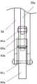
Fig. 1 is a schematic side view of the present invention.
FIG. 2 is a schematic top view of a thermoplastic pipe handling apparatus.
FIG. 3 is a schematic top view of a thermoplastic pipe handling apparatus.
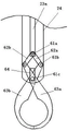
Figure 4 is a side view of a thermoplastic pipe clamp.
Fig. 5 is a schematic end view of a thermoplastic pipe clamp.
Fig. 6 is a schematic side view of the reinforcing bar feeding machine.
Fig. 7 is a schematic end view of the reinforcing bar feeding machine.
FIG. 8 is a schematic side view of the movable roller.
Description of reference numerals: 10-vibration hopper, 11-vibration hopper body, 12-discharge port, 13-photoelectric sensor I, 14-reflector, 15-thermoplastic pipe, 16-steel bar, 17-shelf, 20-thermoplastic pipe handling device, 21-trolley roller, 22-trolley, 23-lifting cylinder, 23 a-lifting cylinder rod, 24-pipe clamp bracket, 25-thermoplastic pipe clamp, 26-guide rail, 27-electric cylinder, 28-connecting rod, 30-clamping pipe penetrating device, 31-discharging motor, 32-steel bar discharging roller, 32 a-fixed roller, 32 b-movable roller, 33 a-photoelectric sensor II, 33 b-photoelectric sensor III, 34-clamping cylinder, 35 a-fixed clamp, 35 b-movable clamp, 36-thermoplastic pipe is provided with a groove, 36 a-baffle plates, 37-moving cylinders, 37 a-moving cylinder rods, 38-sliding rails, 39-sliding plates, 40-moving-in mechanisms, 41-moving-in motors, 42-reinforcing steel bar moving-in rollers, 43-photoelectric sensors, 45-moving-in platforms, 50-reinforcing steel bar feeders, 51-lifting devices, 51 a-vertical suction heads, 51 b-lifting cylinders, 52-temporary storage mechanisms, 52 a-B-shaped structures, 52 b-temporary storage cylinders, 52 c-horizontal storage tables, 53-translation devices, 53 a-horizontal suction heads, 53 b-translation cylinders, 54-horizontal rollers, 55 a-high rollers, 55 b-low rollers, 61 a-first articulated shafts, 61 b-second articulated shafts, 61 c-cross hinge shaft, 62 a-connecting rod I, 62 b-connecting rod II, 63 a-thermoplastic pipe clamp I, 63 a-thermoplastic pipe clamp II, 64-long hole, 70-moving mechanism, 71-moving cylinder frame, 72-rotating shaft bearing, 73-rotating shaft and 74-roller bracket.
Detailed Description
The following describes in detail embodiments of the present invention with reference to the drawings. In the following apparatus, the reinforcing bar is carried in and out along the longitudinal direction of the reinforcing bar, the thermoplastic pipe and the reinforcing bar are brought in from both sides of different heights in opposite directions, the thermoplastic pipe is placed in the thermoplastic pipe installation groove provided in the middle, and the reinforcing bar is inserted into the thermoplastic pipe and heated and then carried out. For the purpose of illustration, the positions of the lifting devices are different in the side view and the end view of the feeder, since the thickness of the steel bars is different. The different positions of the temporary storage mechanism are respectively embodied by a dotted line and a solid line when the temporary storage mechanism rotates.
The technical scheme of the utility model a steel bar periphery interval is worn to establish and is moulded a tub device, and figure 1 is the utility model discloses a side structure schematic diagram. FIG. 2 is a schematic top view of the thermoplastic pipe handling apparatus. The device for alternately penetrating and arranging the thermoplastic pipes on the peripheries of the steel bars comprises a controller, a vibration hopper and a steel bar feeding machine 50, wherein 11 is a vibration hopper main body, 12 is a discharge hole, the vibration hopper and the steel bar feeding machine 50 are respectively arranged at two ends of the device for alternately penetrating and arranging the thermoplastic pipes on the peripheries of the steel bars, a thermoplastic pipe identification device and a thermoplastic pipe carrying device 20 are sequentially arranged at the side of the vibration hopper 10, a clamping pipe penetrating device 30 is arranged below the thermoplastic pipe carrying device 20, the clamping pipe penetrating device 30 comprises a thermoplastic pipe arranging groove 36, a heating device is arranged in the thermoplastic pipe arranging groove 36, a steel bar carrying roller 32 is arranged at one end of the thermoplastic pipe arranging groove 36, the steel bar feeding machine 50 for conveying the steel bars to the clamping pipe penetrating device 30 is arranged on an extension line at the other end of the thermoplastic pipe arranging groove 36, the steel bar feeding machine 50 and the vibration hopper 10 are linked with the thermoplastic pipe identification device, the thermoplastic, the reinforcing bar feeder 50 moves the reinforcing bars 16 along the thermoplastic pipe installation grooves 36 to penetrate into the thermoplastic pipes 15, the thermoplastic pipes 15 are heated by the heating device and then shrunk, and the reinforcing bars 16 are fixed on the outer peripheries of the reinforcing bars 16 at the designed intervals, and then the reinforcing bars 16 are carried out from the outlets of the thermoplastic pipe installation grooves 36 by the reinforcing bar carrying-out rollers 32.
The thermoplastic pipe identification device is a photoelectric sensor I13, the photoelectric sensor I13 is arranged on one side of the front end part of the thermoplastic pipe carrying device 20, a reflective mirror 14 is arranged on the opposite side, and the photoelectric sensor I13 is electrically connected with the controller.
FIG. 3 is a schematic top view of a thermoplastic pipe handling apparatus. The thermoplastic pipe conveying device 20 comprises a guide rail 26, a trolley 22 is arranged on the guide rail 26, trolley rollers 21 are arranged on two sides of the trolley 22, the trolley rollers 21 move back and forth on the guide rail 26, a thermoplastic pipe clamp 25 is arranged below the trolley 22 in the vertical direction, a lifting cylinder 23 is arranged above the thermoplastic pipe clamp 25, 23a is a lifting cylinder rod, a roller shaft of the trolley rollers 21 is connected with a rodless electric cylinder 27 through a connecting rod 28, the rodless electric cylinder is arranged on one side of the guide rail 26, and a servo motor is arranged in the electric cylinder 27 and can accurately control the conveying position of the thermoplastic pipe.
In this embodiment, the trolley 22 is provided with four trolley rollers 21 evenly distributed on two sides, and the two trolley rollers 21 on each side are respectively arranged on two guide rails 26.
Figure 4 is a side view of a thermoplastic pipe clamp. Fig. 5 is a schematic end view of a thermoplastic pipe clamp. The thermoplastic pipe clamp 25 comprises a pair of connecting rods, one end of each connecting rod is hinged at the end part of the cylinder rod, specifically a first connecting rod 62a and a second connecting rod 62b, one end of each connecting rod 62a and the second connecting rod 62b is hinged at the end part of the lifting cylinder rod 23a of the lifting cylinder 23 by a first hinge shaft 61a, the other end of each connecting rod 62a and the second connecting rod 62b is hinged at the upper ends of a first thermoplastic pipe clamp 63a and a second thermoplastic pipe clamp 63b by a second hinge shaft 61b, the thermoplastic pipe clamps 25, namely the first thermoplastic pipe clamp 63a and the second thermoplastic pipe clamp 63b, are hinged at the upper ends in a crossed mode and then are hinged at the other ends of the connecting rods, the crossed positions of the thermoplastic pipe clamps 25 are hinged on the crossed hinge shafts 61c, the two ends of the crossed hinge shafts 61c are movably arranged in long holes 64 at the end parts of the pipe clamp, the lifting distance of the lifting cylinder 23 is larger than the length of the long hole 64, the cylinder rod drives the thermoplastic pipe clamp 25 to lift in the long hole 64, after the cross hinge shaft 61c contacts the lower end of the long hole 64, the thermoplastic pipe clamp 25 is opened, and the thermoplastic pipe clamp 25 clamps the thermoplastic pipe to move in the conveying process or in the lifting process.
The pipe clamping and penetrating device 30 comprises a thermoplastic pipe arranging groove 36, the thermoplastic pipe arranging groove 36 comprises an inlet and an outlet, the inlet is of a horn-shaped structure, the outlet is provided with a baffle plate 36a, and the baffle plate 36a is connected to a cylinder rod of a baffle cylinder. In this embodiment, the baffle cylinder is disposed below the baffle 36a, the third photoelectric sensor 33b is disposed at the middle bottom of the thermoplastic pipe disposing groove 36, when the third photoelectric sensor 33b detects that the steel bar 16 is in place, the controller will instruct the baffle 36a to ascend, and simultaneously, after the second photoelectric sensor 33a disposed at the bottom of the outlet of the thermoplastic pipe disposing groove 36 detects that the steel bar 16 is in place, the steel bar carrying-in roller 42 and the horizontal roller disposed in front of the thermoplastic pipe disposing groove 36 are driven by their respective motors to slowly convey the end of the steel bar to contact with the baffle. After heating is completed, the controller instructs the baffle 36a to avoid the outlet, and the baffle cylinder drives the baffle 36a to descend.
The heating device comprises a fixed clamp 35a and a movable clamp 35b, heating wires are arranged in the fixed clamp 35a and the movable clamp 35b, a clamping cylinder 34 is arranged on the side surface of the movable clamp 35b, after the thermoplastic pipe 15 is placed in a thermoplastic pipe setting groove 36, a photoelectric sensor (not marked in the figure) for detecting the thermoplastic pipe feeds back information to a controller, the corresponding clamping cylinder 34 drives the movable clamp 35b to be close to the fixed clamp 35a to clamp the thermoplastic pipe 15, so that the reinforcing steel bar 16 penetrates into the thermoplastic pipe 15, the thermoplastic pipe 15 is heated after the reinforcing steel bar penetrates, and the thermoplastic pipe 15 keeps a cylindrical structure when the movable clamp 35b and the fixed clamp 32a clamp the thermoplastic pipe 15.
The steel bar carrying-out roller 32 and the steel bar carrying-in roller 42 comprise a pair of rollers with horizontally arranged end surfaces, the steel bar carrying-out roller 32 is arranged at one end close to an outlet of the thermoplastic pipe provided with the groove 36, the steel bar carrying-in roller 42 is arranged at one end close to the inlet of the thermoplastic pipe provided with the groove 36, the pair of steel bar carrying-out rollers 32 or the steel bar carrying-in roller 42 comprise a fixed roller 32a and a movable roller 32b, the bottom of one end of the thermoplastic pipe provided with the outlet of the groove 36 is provided with a second photoelectric sensor 33a, the middle position of the thermoplastic pipe provided with the groove 36 is provided with a third photoelectric sensor 33b, the photoelectric sensors are respectively used for detecting the in-place and the entering of.
In this embodiment, the reinforcing bar feeding machine 50 is a reinforcing bar feeding machine of a reinforcing mesh production line, which is disclosed in application No. 2018209935041. A rebar feeder of application No. 2018209935272 may also be used, as well as a shelf-interactive rebar feeder of application No. 2018209935056 or a shelf-interactive rebar feeder of application No. 2018209935268.
Fig. 6 is a side view of the reinforcing bar feeder. Fig. 7 is a schematic end view of the reinforcing bar feeding machine.
The reinforcing steel bar feeding machine 50 comprises a lifting device 51, a temporary storage mechanism 52, a translation device 53, a reinforcing steel bar carrying-in roller 42, four mechanisms are respectively provided with respective cylinders, the lifting device 51 comprises a lifting cylinder 51b, the translation device 53 comprises a translation cylinder 53b, the end parts of cylinder bars of the lifting cylinder 51b and the translation cylinder 53b are respectively provided with a vertical suction head 51a and a horizontal suction head 53a, the temporary storage mechanism 52 comprises a rotary type 'b' shaped structure 52a, the upper end of the 'b' shaped structure 52a is connected with the temporary storage cylinder 52b, the middle of the 'b' shaped structure 52a is provided with a rotating shaft, the 'b' shaped structure 52a can rotate by taking the rotating shaft as a rotating center in the temporary storage process of a cylinder rod of the cylinder 52b, the lower end of the rotating shaft can leave a vertical line passing through the rotating shaft, so as to avoid the lifting of the vertical suction head 51, that is, the cylinder rod is contracted to rotate the "b" shaped structure 52a, after the rotation, the "b" shaped structure 52a can avoid the lifting of the lifting device 51 vertical sucker 51a, after the rotation, the "b" shaped structure 52a is provided with the horizontal storage platform 52c, after the lifting cylinder 51b sucks the reinforcing steel bar 16 to lift, the vertical sucker 51a and the sucked reinforcing steel bar 16 are lifted to the height of the horizontal storage platform 52c of the "b" shaped structure 52a, the cylinder rod of the temporary storage cylinder 52b is extended, the horizontal storage platform 52c of the "b" shaped structure 52a is rotated to the horizontal state, the electromagnetic sucker in the vertical sucker 51a releases the magnetic force, the reinforcing steel bar 16 on the vertical sucker 51a is placed on the horizontal storage platform 52c, the horizontal sucker 53a is connected with the end part of the air rod of the translation cylinder 53b, after the horizontal sucker 53a of the translation device 53 is extended, the nearest reinforcing steel bar 16 on the horizontal storage platform 52c can be sucked, after the cylinder rod of the translation cylinder 53b is contracted, the reinforcing bar 16 is positioned just above the carry-in table 45 between the pair of reinforcing bar carry-in rollers 42 of the carry-in mechanism 40, and the reinforcing bar 16 can be released onto the carry-in table 45 between the reinforcing bar carry-in rollers 42. The horizontal suction head 53a of the translation device 53 sequentially sucks the nearest steel bars 16 on the horizontal storage table 52c until the suction is finished, and then the vertical suction head 51a of the lifting device 51 of the steel bar feeding machine repeatedly sucks the steel bars 16 on the shelf 17 for the translation device 53 to translate one by one.
The carrying-in mechanism 40 comprises a reinforcing steel bar carrying-in roller 42, the carrying-in roller 42 and the carrying-out roller have the same structure and are provided with a fixed roller 32a and a movable roller 32b, the reinforcing steel bar carrying-in roller 42 is arranged on an extension line at one side of the inlet of the thermoplastic pipe arrangement groove 36, 41 is a carrying-in motor, the carrying-in motor is a speed reduction motor and is connected with the fixed roller 32a, the carrying-in mechanism 40 comprises at least a pair of reinforcing steel bar carrying-in rollers 42, a carrying-in platform 45 is arranged between the reinforcing steel bar carrying-in rollers 42, the carrying-in platform 45 is arranged on a frame, a photoelectric sensor four 43 is arranged on the carrying-in platform 45, a movable cylinder 37 of the reinforcing steel bar carrying-in roller 42 can drive the movable roller 32b to be close to the fixed roller 32a to clamp the reinforcing steel bar 16 through the instruction of a controller, and the movable roller can move to the thermoplastic pipe arrangement, while passing into the thermoplastic tube. In this embodiment, the carrying-in mechanism 40 is provided with two pairs of steel bar carrying-in rollers 42, the two pairs of steel bar carrying-in rollers 42 are controlled by the controller to act synchronously, the thermoplastic pipe arrangement groove 36 is lower than the height of the vibration hopper 10 and the discharge port 12 thereof, the discharge port 12 of the vibration hopper is of a bending structure, and the carrying-out of the steel bar at the outlet of the thermoplastic pipe arrangement groove 36 is not affected.
Fig. 8 is a side view schematically showing the structure of the moving roller. 70 is a moving mechanism, 70 is a moving mechanism 70 of moving roller in the steel bar carrying-in roller 42 and the steel bar carrying-out roller 32, 70 includes a roller bracket 74, the moving mechanism 70 is provided with a moving cylinder frame 71, a moving cylinder 37 is fixed on the moving cylinder frame 71, the end of the moving cylinder rod 37a is connected to the sliding plate 39, the steel bar carrying-out roller 32 and the steel bar carrying-in roller 42 are arranged in the same way, the steel bar carrying-out roller 32 or the steel bar carrying-in roller 42 is a pair of rollers with horizontal end surfaces, 31 is a carrying-out motor, the carrying-out motor 31 is connected with the rotating shaft 73 of the fixed roller 32a of the carrying-out roller, the rotating shaft 73 of the moving roller 32b is vertically arranged on the sliding plate 39 with horizontal arrangement through a bearing 72, the sliding rail 38 is arranged on both sides of the sliding plate 39, the end of the sliding plate 39 is connected with the moving cylinder 37, 37a, the moving cylinder 37 drives the sliding plate 39 to move along the sliding rail 38, and drives the moving roller 32b to approach the fixed roller 32a, thereby clamping the reinforcing bar 16.
The platform 45 of moving into is provided with horizontal roller 54, and the reinforcing bar transmission line both sides are provided with perpendicular gyro wheel on the rack, and the perpendicular roller height of reinforcing bar goods shelves 17 one side is less than the perpendicular roller height of opposite side, and 55a is high gyro wheel, and 55b is low running roller, horizontal suction head 53a and perpendicular suction head 51a are the magnetic suction head, are connected with horizontal roller driving motor on the horizontal roller 54 before thermoplastic pipe sets up recess 36, set up perpendicular running roller mainly in order to prevent the reinforcing bar horizontal hunting in the data send process, and the low running roller is the reinforcing bar translation of the translation device 53 of being convenient for. And a horizontal roller driving motor connected to the horizontal roller 54 before entering the thermoplastic pipe installation groove 36, wherein the horizontal roller driving motor drives the horizontal roller to roll, and the reinforcing steel bar is fed to the last pass in the thermoplastic pipe installation groove 36.
The utility model discloses a set up vibration hopper 10, can arrange in proper order at vibration hopper 10 discharge gate 12 thermoplastic pipe 15 according to thermoplastic pipe 15 length direction, through set up thermoplastic pipe photoelectric sensor 13 between vibration hopper 10 and thermoplastic pipe handling device 20, can feed back to the controller with each thermoplastic pipe 15 information that detects through photoelectric sensor 13, the controller can control servo motor and lift cylinder 23 in the thermoplastic pipe handling device 20 electric jar 27 respectively according to the information of thermoplastic pipe 15, make thermoplastic pipe handling device 20 carry out the transport of thermoplastic pipe 15, carry thermoplastic pipe 15 respectively to thermoplastic pipe handling device 20 top according to the distance that sets up on reinforcing bar 16, and utilize lift cylinder 23 to set up the corresponding position in the thermoplastic pipe setting groove; a thermoplastic pipe arranging groove 36 is formed below the thermoplastic pipe carrying device 20, a heating device is arranged in the thermoplastic pipe arranging groove 36 and comprises a fixing clamp 35a and a moving clamp 35b, heating wires are arranged in the fixing clamp 35a and the moving clamp 35b, a clamping cylinder 34 is arranged on the side face of the moving clamp 35b, on one hand, the thermoplastic pipe 15 can be fixed, and in addition, the heating wires are arranged in the fixing clamp 35a and the moving clamp 35b through the heating device, the thermoplastic pipe 15 can be heated, so that the thermoplastic pipe 15 is fixed on the periphery of the reinforcing steel bar 16 through thermal contraction; by arranging a steel bar feeding machine 50 for conveying steel bars to the direction of the thermoplastic pipe arrangement groove 36 on the groove extension line in front of the thermoplastic pipe arrangement groove 36, the end part of the steel bar on the ground hung in front of the shelf 17 can be sucked up by using a vertical suction head 51a of a lifting device 51 of the steel bar feeding machine, the sucked steel bar is placed on a horizontal storage platform 52c of the temporary storage mechanism 52 after the temporary storage mechanism 52 of a B-shaped structure 52a rotates, then the steel bars stored on the horizontal storage platform 52c of the temporary storage mechanism 52 are sequentially conveyed to a conveying platform 45 between a pair of steel bar conveying rollers 42 one by using a horizontal suction head 53a of a translation device 53, a photoelectric sensor four 43 arranged on the conveying platform 45 can detect the in-place of the steel bar, and the steel bar conveying rollers 42 are instructed by a controller to be conveyed into the thermoplastic pipe arrangement groove along a horn mouth in front of the thermoplastic pipe arrangement groove; by arranging the steel bar carrying-in roller 42, the steel bar 16 can be sent into the thermoplastic pipe arranging groove 36 from the bell mouth at the end part of the thermoplastic pipe arranging groove 36, and the steel bar 16 is arranged in the thermoplastic pipe 15 in a penetrating way, in the carrying-in process of the steel bar 16, the three photoelectric sensors 33b arranged at the bottom of the thermoplastic pipe arranging groove 36 can detect the carrying-in of the steel bar 16, the baffle plate arranged at the outlet end of the thermoplastic pipe arranging groove 36 can rise to block the steel bar 16, when the steel bar 16 reaches the outlet end of the thermoplastic pipe arranging groove 36, the two photoelectric sensors 33a can detect the in-place of the steel bar 16, the conveying of the steel bar 16 is stopped, then the thermoplastic pipe 15 is heated by the heating device, the thermoplastic pipe 15 is contracted to the periphery of the steel bar 16, the fixation of the thermoplastic pipe 15 of the steel bar 16 at the plurality of steel bar net crossing positions at the periphery of the steel bar 16 is realized, the baffle plate 36, the reinforcing bar carrying-out roller 32 can realize automatic carrying-out of the reinforcing bar. Through utilizing the utility model discloses, can realize insulating plastics thermoplastic pipe 15's automation and put, wear to establish, thermal contraction can replace the manual work and wear to establish, can improve thermoplastic pipe 15 wear to establish efficiency, reduces workman's intensity of labour, eliminates vortex, stray current that ballastless track produced when the train passes through, improves passenger dedicated line system's operating stability.
Claims (10)
1. The utility model provides a thermoplastic pipe device is worn to establish at long reinforcing bar periphery interval, includes controller, vibration hopper and reinforcing bar material loading machine, its characterized in that: vibration hopper and reinforcing bar material loading machine set up respectively and wear to establish the both ends of thermoplasticity pipe device at reinforcing bar periphery interval, it establishes other device to have set gradually the thermoplasticity pipe behind the vibration hopper, thermoplasticity pipe handling device, be provided with below the thermoplasticity pipe handling device and press from both sides tight poling device, press from both sides tight poling device and set up the recess including the thermoplasticity pipe, the thermoplasticity pipe sets up and is provided with the reinforcing bar and remove the gyro wheel, it sets up the reinforcing bar material loading machine to press from both sides tight poling device conveying reinforcing bar to be provided with on the extension cord of the recess other end to thermoplasticity pipe, reinforcing bar material loading machine and vibration hopper pass through controller and thermoplasticity pipe and establish other device, thermoplasticity pipe handling device and press from both sides tight poling device linkage, reinforcing bar material loading machine makes the reinforcing.
2. The device for inserting thermoplastic pipes at intervals on the periphery of long steel bars according to claim 1, wherein: the thermoplastic pipe is provided with a first photoelectric sensor, the first photoelectric sensor is arranged on one side of the end part of the thermoplastic pipe carrying device, and a reflector is arranged on the opposite side.
3. The device for inserting thermoplastic pipes at intervals on the periphery of long steel bars according to claim 1, wherein: the thermoplastic pipe carrying device comprises a guide rail, wherein a trolley is arranged on the guide rail, trolley rollers are arranged on two sides of the trolley, the trolley rollers move back and forth on the guide rail, a thermoplastic pipe clamp is arranged vertically below the trolley, a lifting cylinder is arranged above the thermoplastic pipe clamp, and the trolley is connected with an electric cylinder through a connecting rod.
4. The device for inserting thermoplastic pipes at intervals on the periphery of long steel bars according to claim 1, wherein: the thermoplastic pipe is provided with the groove and comprises an inlet and an outlet, the inlet is of a horn-shaped structure, the outlet is provided with a baffle plate, the baffle plate is connected to a cylinder rod of a baffle plate cylinder, and the thermoplastic pipe is provided with the groove which is lower than the vibration hopper and the discharge port height thereof.
5. The device for inserting thermoplastic pipes at intervals on the periphery of long steel bars according to claim 1, wherein: the heating device comprises a fixing clamp and a movable clamp, wherein heating wires are arranged in the fixing clamp and the movable clamp, and a clamping cylinder is arranged on the side surface of the movable clamp.
6. The device for inserting thermoplastic pipes at intervals on the periphery of long steel bars according to claim 1, wherein: the structure that the gyro wheel was moved out to the reinforcing bar is the same with the structure that the gyro wheel was moved into to the reinforcing bar, all includes a pair of gyro wheel of terminal surface in the coplanar, and the gyro wheel is including removing gyro wheel and fixed roller, and the pivot of removing the gyro wheel passes through the bearing and sets up perpendicularly on the slide, and the both sides of slide are provided with the slide rail, and the end connection of slide has moving cylinder, and when pressing from both sides tight reinforcing bar, moving cylinder drives the slide and removes along the slide rail, drives moving roller and is close to fixed roller.
7. The device for inserting thermoplastic pipes at intervals on the periphery of long steel bars according to claim 1, wherein: reinforcing bar material loading machine includes hoisting device, the temporary storage mechanism, the translation device, four mechanisms of gyro wheel are moved into to the reinforcing bar, four mechanisms all are provided with respective cylinder, wherein hoisting device, the translation device is respectively including promoting cylinder and translation cylinder, cylinder thick stick tip is provided with perpendicular suction head and horizontal suction head respectively, the temporary storage mechanism is including the "B" font structure of rotation type, "the platform is deposited to the level of being provided with on the structure of" B "font, reinforcing bar material loading machine is moved into platform surface level and is provided with a pair of reinforcing bar and moves into the gyro wheel, it is provided with the photoelectric sensor who does not distinguish the reinforcing bar and target in place to move into.
8. The device for inserting thermoplastic pipes at intervals on the periphery of long steel bars according to claim 1, wherein: the structure that the gyro wheel was moved out to the reinforcing bar is the same with the structure that the gyro wheel was moved into to the reinforcing bar, all includes a pair of gyro wheel of terminal surface in the coplanar, and a pair of gyro wheel is including removing gyro wheel and fixed roller, and the pivot of removing the gyro wheel passes through the bearing and sets up perpendicularly on the slide, and the both sides of slide are provided with the slide rail, and the end connection of slide has the moving cylinder, and when pressing from both sides tight reinforcing bar, the moving cylinder drives the slide and removes along the slide rail, drives and removes the gyro wheel and.
9. The device for inserting thermoplastic pipes at intervals on the periphery of long steel bars according to claim 3, wherein: the thermoplastic pipe clamp comprises a pair of connecting rods, one ends of the connecting rods are hinged to the end portion of the air cylinder rod, the thermoplastic pipe clamp is hinged to the other ends of the connecting rods after being hinged in a crossed mode, a pair of thermoplastic pipe clamp cross hinge shafts are movably connected into a long hole in the end portion of the pipe clamp support, the lifting distance of the lifting air cylinder is larger than the length of the long hole, the air cylinder rod drives the thermoplastic pipe clamp to lift in the long hole, after the cross hinge shafts contact the lower end of the long hole, the thermoplastic pipe clamp opens, and the thermoplastic pipe clamp is closed in the.
10. The apparatus of claim 7 wherein the means for inserting the thermoplastic pipe at the peripheral intervals of the long reinforcing bars comprises: the moving platform is provided with a plurality of horizontal rollers, the two sides of the steel bar moving line on the rack are provided with vertical rollers, the height of the vertical roller on one side of the steel bar shelf is smaller than that of the vertical roller on the opposite side, and the horizontal suction head and the vertical suction head are magnetic suction heads.
Priority Applications (1)
| Application Number | Priority Date | Filing Date | Title |
|---|---|---|---|
| CN201821200478.9U CN211891969U (en) | 2018-07-27 | 2018-07-27 | Thermoplastic pipe device is worn to establish at long reinforcing bar periphery interval |
Applications Claiming Priority (1)
| Application Number | Priority Date | Filing Date | Title |
|---|---|---|---|
| CN201821200478.9U CN211891969U (en) | 2018-07-27 | 2018-07-27 | Thermoplastic pipe device is worn to establish at long reinforcing bar periphery interval |
Publications (1)
| Publication Number | Publication Date |
|---|---|
| CN211891969U true CN211891969U (en) | 2020-11-10 |
Family
ID=73282148
Family Applications (1)
| Application Number | Title | Priority Date | Filing Date |
|---|---|---|---|
| CN201821200478.9U Active CN211891969U (en) | 2018-07-27 | 2018-07-27 | Thermoplastic pipe device is worn to establish at long reinforcing bar periphery interval |
Country Status (1)
| Country | Link |
|---|---|
| CN (1) | CN211891969U (en) |
Cited By (2)
| Publication number | Priority date | Publication date | Assignee | Title |
|---|---|---|---|---|
| CN112406086A (en) * | 2020-12-11 | 2021-02-26 | 湖南振辉管业有限公司 | Metal plastic composite pipe compounding equipment and compounding process |
| CN113524713A (en) * | 2021-09-16 | 2021-10-22 | 辽宁美托科技股份有限公司 | Automatic device for penetrating long steel bars into multi-section heat shrinkable tubes |
-
2018
- 2018-07-27 CN CN201821200478.9U patent/CN211891969U/en active Active
Cited By (4)
| Publication number | Priority date | Publication date | Assignee | Title |
|---|---|---|---|---|
| CN112406086A (en) * | 2020-12-11 | 2021-02-26 | 湖南振辉管业有限公司 | Metal plastic composite pipe compounding equipment and compounding process |
| CN112406086B (en) * | 2020-12-11 | 2023-11-24 | 湖南振辉管业有限公司 | Metal plastic composite pipe compounding equipment and compounding process |
| CN113524713A (en) * | 2021-09-16 | 2021-10-22 | 辽宁美托科技股份有限公司 | Automatic device for penetrating long steel bars into multi-section heat shrinkable tubes |
| CN113524713B (en) * | 2021-09-16 | 2022-01-21 | 辽宁美托科技股份有限公司 | Automatic device for penetrating long steel bars into multi-section heat shrinkable tubes |
Similar Documents
| Publication | Publication Date | Title |
|---|---|---|
| US3732052A (en) | Apparatus for the continuous manufacture of precast reinforced concrete products, particularly slabs and beams | |
| CN211891969U (en) | Thermoplastic pipe device is worn to establish at long reinforcing bar periphery interval | |
| CN206598298U (en) | A kind of autohub grabbing device | |
| CN108973106B (en) | Method for penetrating steel bar insulating sleeve | |
| CN111069826A (en) | Automatic welding production line for steel structure | |
| CN108859095B (en) | Method for penetrating thermoplastic pipes at intervals on periphery of reinforcing steel bars | |
| CN207615576U (en) | A kind of pier head machine convenient for feeding | |
| RU2062858C1 (en) | Track-packing machine for switches and railroad crossings | |
| WO2012005883A1 (en) | Drone tamper | |
| CN210679721U (en) | Thermoplastic pipe device is worn to establish at reinforcing bar periphery interval | |
| CN207756702U (en) | Automatic charging punching apparatus and ripple board processing system | |
| CN104589434A (en) | Composite body automatic nailing machine clamping and turning mechanism | |
| CN110524710A (en) | A kind of steam-pressing aero-concrete is laid bricks the technique rejected defect idiosome and be subject to reuse | |
| CN109353835A (en) | A kind of automatic high speed segment palletizing production line | |
| CA2139688A1 (en) | Method and apparatus for row-wise separation of rectilinear, plastic porous concrete bodies | |
| CN205346337U (en) | Brick board separation pile up neatly device | |
| CN209738151U (en) | Injection molding production line for steel bar insulation layer | |
| CN203473729U (en) | Bulk bar material grouping feeding device | |
| CN111112722A (en) | Automatic accurate sampling device of steel sheet production line | |
| CN103496542A (en) | Bar bulk material grouping and feeding device | |
| CN206913408U (en) | A kind of cloth hopper interposition scraper exempts from the control device of interim card | |
| CN2528576Y (en) | Manipulator autoamtic feeding equipment | |
| CN106181547B (en) | Feeding mechanical hand and ball blast shear loading and unloading automatic system | |
| CN212988775U (en) | Mechanical running and testing equipment for high-voltage circuit breaker | |
| SU1547714A3 (en) | Sleeper-tamping machine |
Legal Events
| Date | Code | Title | Description |
|---|---|---|---|
| GR01 | Patent grant | ||
| GR01 | Patent grant |