CN211890378U - Full-automatic elbow polishing machine - Google Patents
Full-automatic elbow polishing machine Download PDFInfo
- Publication number
- CN211890378U CN211890378U CN202020064576.5U CN202020064576U CN211890378U CN 211890378 U CN211890378 U CN 211890378U CN 202020064576 U CN202020064576 U CN 202020064576U CN 211890378 U CN211890378 U CN 211890378U
- Authority
- CN
- China
- Prior art keywords
- polishing
- equipment box
- face
- positioning
- machine shell
- Prior art date
- Legal status (The legal status is an assumption and is not a legal conclusion. Google has not performed a legal analysis and makes no representation as to the accuracy of the status listed.)
- Active
Links
Images



Landscapes
- Grinding-Machine Dressing And Accessory Apparatuses (AREA)
- Finish Polishing, Edge Sharpening, And Grinding By Specific Grinding Devices (AREA)
Abstract
The utility model discloses a full-automatic elbow polishing machine, including equipment box, casing, protection casing, first locating component, polishing subassembly, second locating component, first electric putter, dust removal subassembly, ventilation groove, electric cabinet, power plug and supporting legs, there is the casing top terminal surface one side of equipment box through bolt fixed mounting, there is the protection casing top through screw fixed mounting at the casing top, a side end face of casing is provided with first locating component, another side end face of casing is provided with the second locating component, the bottom of second locating component is provided with first electric putter, the inside of casing is provided with the polishing subassembly, the inside of equipment box is provided with the dust removal subassembly; the full-automatic elbow polishing machine is small in structure and volume, simple to operate when in use, capable of polishing elbows and good in polishing effect; meanwhile, dust generated by polishing can be cleaned and absorbed, and the cleaning convenience is improved.
Description
Technical Field
The utility model relates to a pipeline polishing equipment field specifically is a full-automatic return bend burnishing machine.
Background
The polishing machine is a material surface processing device, can remove paint surface pollution, oxide layers and shallow marks, and is widely used for rust removal and polishing in the industries of hardware manufacturing, vehicle accessories, steel and wood furniture, instrument machinery, standard parts, before and after electroplating and the like; in the prior art, a polishing machine usually polishes a straight pipeline, when a bent pipe is polished, the polishing effect is poor, dust is easily generated on the surface of the bent pipe during polishing, and the dust is inconvenient to clean during sputtering, so that the design of a full-automatic bent pipe polishing machine is necessary.
SUMMERY OF THE UTILITY MODEL
The utility model aims at providing a full-automatic elbow polishing machine which has small structure and small volume, is simple to operate when in use, can polish elbows and has good polishing effect; meanwhile, dust generated by polishing can be cleaned and absorbed, and the cleaning convenience is improved.
The purpose of the utility model can be realized by the following technical scheme:
a full-automatic elbow polishing machine comprises an equipment box, a casing, a protective cover, a first positioning assembly, a polishing assembly, a second positioning assembly, a first electric push rod, a dust removal assembly, a ventilation groove, an electric cabinet, a power plug and supporting legs, wherein the casing is fixedly installed on one side of the top end face of the equipment box through a bolt, the protective cover is fixedly installed on the top of the casing through a screw, the first positioning assembly is arranged on the end face of one side of the casing, the second positioning assembly is arranged on the end face of the other side of the casing, the first electric push rod is arranged at the bottom of the second positioning assembly, the polishing assembly is arranged inside the casing, and the dust removal assembly is arranged inside the equipment box;
the polishing assembly comprises a polishing slot, a polishing grinding wheel, a driven shaft, a rotating bearing, a transmission belt, a driving shaft and a polishing motor, wherein the polishing slot is formed in the central position of the side face of the casing, the polishing motor is fixedly installed on the two sides of the inside of the casing through screws respectively, the driving shaft is installed on one side of the polishing motor in a connected mode, the transmission belt is installed on the outer side of the driving shaft in a sleeved mode, the polishing grinding wheel is arranged on the two sides of the polishing slot respectively, the driven shaft is installed on the end faces of the two sides of the polishing grinding wheel in a connected mode, the other side of the transmission belt is installed on the outer side of the driven shaft in a sleeved.
As a further aspect of the present invention: supporting legs are fixedly mounted at the corners of the periphery of the end face of the bottom of the equipment box through screws.
As a further aspect of the present invention: an electric cabinet is fixedly installed on one side of the end face of the front end of the equipment box through screws, and a power plug is installed inside the electric cabinet in an inserted mode.
As a further aspect of the present invention: first locating component and second locating component all include roof location, second electric putter and gag lever post, first locating component's roof location passes through a side end face at the casing of screw fixed mounting, second locating component's roof location passes through screw fixed mounting at first electric putter's top end face, and the top end face fixed connection of first electric putter's bottom and equipment box, there is second electric putter top end face one side of roof location through screw fixed mounting, the gag lever post is installed in the top one end connection of second electric putter.
As a further aspect of the present invention: the ventilation groove is formed in the center of the end face of one side of the equipment box and communicated with the inside of the equipment box.
As a further aspect of the present invention: the dust removal component comprises a mounting rack, a dust collector, a dust collection pipe and a blanking cover, the mounting rack is fixedly mounted in the equipment box through screws, the dust collector is mounted on the top end face of the mounting rack through screws, the dust collection pipe is connected and mounted at a dust collection opening on one side of the dust collector, the blanking cover is installed by penetrating one end of the dust collection pipe through the equipment box and the casing, and the blanking cover is communicated with the polishing slot.
The utility model has the advantages that: the full-automatic elbow polishing machine is small in structure and small in size, is simple to operate when in use, can clamp and fix an elbow through the positioning assembly, and can polish the elbow through the polishing assembly, so that the full-automatic elbow polishing machine has a good polishing effect; meanwhile, during polishing, dust generated by polishing can be cleaned and absorbed through the dust removal assembly, the dust floating condition is avoided, and the cleaning convenience is improved.
Drawings
In order to facilitate understanding for those skilled in the art, the present invention will be further described with reference to the accompanying drawings.
FIG. 1 is a schematic view of the overall structure of the present invention;
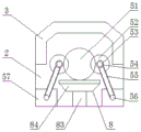
fig. 2 is a sectional view of the housing of the present invention;
fig. 3 is a top view of the housing of the present invention;
fig. 4 is a schematic structural diagram of the first positioning assembly of the present invention;
fig. 5 is a sectional view of the equipment box of the present invention;
in the figure: 1. an equipment box; 2. a housing; 3. a protective cover; 4. a first positioning assembly; 5. a polishing assembly; 6. a second positioning assembly; 7. a first electric push rod; 8. a dust removal assembly; 9. a ventilation slot; 10. an electric cabinet; 11. a power plug; 12. supporting legs; 41. positioning a top plate; 42. a second electric push rod; 43. a limiting rod; 51. polishing the slot; 52. polishing the grinding wheel; 53. a driven shaft; 54. a rotating bearing; 55. a transmission belt; 56. a drive shaft; 57. polishing the motor; 81. a mounting frame; 82. a vacuum cleaner; 83. a dust collection pipe; 84. and a blanking cover.
Detailed Description
The technical solution of the present invention will be described clearly and completely with reference to the following embodiments, and it should be understood that the described embodiments are only a part of the embodiments of the present invention, and not all of the embodiments. Based on the embodiments in the present invention, all other embodiments obtained by a person skilled in the art without creative efforts belong to the protection scope of the present invention.
As shown in fig. 1-5, a full-automatic elbow polishing machine comprises an equipment box 1, a machine shell 2, a protective cover 3, a first positioning component 4, a polishing component 5, a second positioning component 6, a first electric push rod 7, a dust removing component 8, a ventilation groove 9, an electric cabinet 10, a power plug 11 and supporting legs 12, wherein the supporting legs 12 are fixedly arranged at the corners of the periphery of the end surface of the bottom of the equipment box 1 through screws, so that the equipment box 1 is conveniently supported; an electric cabinet 10 is fixedly arranged on one side of the front end face of the equipment box 1 through screws, and a power plug 11 is inserted and arranged in the electric cabinet 10 so as to be conveniently connected with an external power supply; a ventilation groove 9 is formed in the center of the end face of one side of the equipment box 1, and the ventilation groove 9 is communicated with the inside of the equipment box 1, so that the equipment box 1 can be conveniently ventilated with the outside; a machine shell 2 is fixedly arranged on one side of the top end face of the equipment box 1 through bolts, a protective cover 3 is fixedly arranged on the top of the machine shell 2 through screws, a first positioning component 4 is arranged on one side end face of the machine shell 2, a second positioning component 6 is arranged on the other side end face of the machine shell 2, a first electric push rod 7 is arranged on the bottom of the second positioning component 6, the first positioning component 4 and the second positioning component 6 respectively comprise a positioning top plate 41, a second electric push rod 42 and a limiting rod 43, the positioning top plate 41 of the first positioning component 4 is fixedly arranged on one side end face of the machine shell 2 through screws, the positioning top plate 41 of the second positioning component 6 is fixedly arranged on the top end face of the first electric push rod 7 through screws, the bottom of the first electric push rod 7 is fixedly connected with the top end face of the equipment box 1, and a second electric push rod 42 is fixedly arranged on one, one end of the top of the second electric push rod 42 is connected with a limiting rod 43, so that the bent pipe can be clamped and fixed conveniently; the polishing assembly 5 is arranged in the machine shell 2, the polishing assembly 5 comprises a polishing slot 51, a polishing grinding wheel 52, a driven shaft 53, a rotating bearing 54, a transmission belt 55, a driving shaft 56 and a polishing motor 57, the polishing slot 51 is arranged at the central position of the side surface of the machine shell 2, the polishing motor 57 is respectively fixedly arranged on two sides of the interior of the machine shell 2 through screws, the driving shaft 56 is connected and arranged on one side of the polishing motor 57, the transmission belt 55 is sleeved and arranged on the outer side of the driving shaft 56, the polishing grinding wheel 52 is respectively arranged on two sides of the polishing slot 51, the end surfaces of two sides of the polishing grinding wheel 52 are connected and arranged on the driven shaft 53, the other side of the transmission belt 55 is sleeved and arranged on the outer side of the driven shaft 53, the; a dust removal component 8 is arranged in the equipment box 1; dust removal component 8 includes mounting bracket 81, dust catcher 82, dust absorption pipe 83 and blanking cover 84, mounting bracket 81 passes through screw fixed mounting in the inside of equipment box 1, there is dust catcher 82 at the top terminal surface of mounting bracket 81 through screw fixed mounting, dust absorption pipe 83 is installed in the connection of one side dust absorption mouth of dust catcher 82, equipment box 1 is passed to the one end of dust absorption pipe 83, casing 2 is connected and is installed blanking cover 84, and blanking cover 84 and polishing slot 51 intercommunication, can be convenient for absorb the dust that the polishing produced cleanly.
The utility model discloses a theory of operation: when the polishing device is used, the equipment box 1 can be supported through the supporting legs 12, the polishing device is connected with an external power supply through the power plug 11, the electric control box 10 is electrified, the polishing device 5 is used for polishing, one end of the bent pipe is limited through the first positioning component 4, the second electric push rod 42 at the top of the positioning top plate 41 works to push the limiting rod 43 to lift, one end of the bent pipe is placed at the top of the positioning top rod and inserted into the polishing slot 51 in the shell 2 through the first positioning component 4, the second electric push rod 42 moves downwards to drive the limiting rod 43 to clamp one end of the bent pipe, the polishing motor 57 works to drive the driving shaft 56 to rotate, the driven shaft 53 is rotated through the driving belt 55, two ends of the driven shaft 53 rotate in the rotating bearing 54, the driven shaft 53 drives the polishing grinding wheel 52 to be in contact with one end of the bent pipe, so that the bent pipe can be polished, the dust removal component 8 works, the dust collector 82 at the top of the mounting frame 81 works to generate suction, dust generated by grinding can be absorbed through the dust collection pipe 83 and the blanking cover 84, the dust is recycled and cleaned through the dust collector 82, one end of the polished elbow passes through the polishing slot 51, due to the structural characteristics of the elbow, the first electric push rod 7 works to adjust the height of the second positioning component 6, the electric push rod drives the positioning push plate to lift, the second electric push rod 42 can drive the limiting rod 43 to lift until one end of the polished elbow is limited, and subsequent elbow grinding is facilitated; the protection casing 3 can have the protective effect to casing 2, and ventilation groove 9 can be convenient for 1 inside and external ventilation of equipment box.
The preferred embodiments of the present invention disclosed above are intended only to help illustrate the present invention. The preferred embodiments are not intended to be exhaustive or to limit the invention to the precise embodiments disclosed. Obviously, many modifications and variations are possible in light of the above teaching. The embodiments were chosen and described in order to best explain the principles of the invention and its practical applications, to thereby enable others skilled in the art to best understand the invention for and utilize the invention. The present invention is limited only by the claims and their full scope and equivalents.
Claims (6)
1. A full-automatic elbow polishing machine is characterized by comprising an equipment box (1), a machine shell (2), a protective cover (3), a first positioning component (4), a polishing component (5), a second positioning component (6), a first electric push rod (7), a dust removal component (8), a ventilation groove (9), an electric cabinet (10), a power plug (11) and supporting legs (12), wherein the machine shell (2) is fixedly installed on one side of the top end face of the equipment box (1) through bolts, the protective cover (3) is fixedly installed on the top of the machine shell (2) through screws, the first positioning component (4) is arranged on one side end face of the machine shell (2), the second positioning component (6) is arranged on the other side end face of the machine shell (2), the first electric push rod (7) is arranged at the bottom of the second positioning component (6), the polishing component (5) is arranged inside the machine shell (2), a dust removal component (8) is arranged in the equipment box (1);
the polishing component (5) comprises a polishing slot (51), a polishing grinding wheel (52), a driven shaft (53), a rotating bearing (54), a transmission belt (55), a driving shaft (56) and a polishing motor (57), wherein the polishing slot (51) is formed in the central position of the side face of the machine shell (2), the polishing motor (57) is fixedly installed on two sides of the inner portion of the machine shell (2) through screws respectively, the driving shaft (56) is installed on one side of the polishing motor (57) in a connected mode, the transmission belt (55) is installed on the outer side of the driving shaft (56) in a sleeved mode, the polishing grinding wheel (52) is arranged on two sides of the polishing slot (51) respectively, the driven shaft (53) is installed on end faces of two sides of the polishing grinding wheel (52) in a connected mode, the other side of the driving shaft (55) is installed on the outer side of the, and the rotating bearing (54) is fixedly arranged at the end surface position of the machine shell (2).
2. The full-automatic elbow polishing machine according to claim 1, characterized in that the four corners of the bottom end surface of the equipment box (1) are fixedly provided with supporting feet (12) by screws.
3. The full-automatic elbow polishing machine according to claim 1, wherein an electric cabinet (10) is fixedly installed on one side of the front end face of the equipment box (1) through screws, and a power plug (11) is inserted and installed inside the electric cabinet (10).
4. The full-automatic elbow polishing machine according to claim 1, wherein the first positioning assembly (4) and the second positioning assembly (6) each comprise a positioning top plate (41), a second electric push rod (42) and a limiting rod (43), the positioning top plate (41) of the first positioning assembly (4) is fixedly installed on one side end face of the machine shell (2) through a screw, the positioning top plate (41) of the second positioning assembly (6) is fixedly installed on the top end face of the first electric push rod (7) through a screw, the bottom of the first electric push rod (7) is fixedly connected with the top end face of the equipment box (1), the second electric push rod (42) is fixedly installed on one side of the top end face of the positioning top plate (41) through a screw, and the limiting rod (43) is installed at one end of the top of the second electric push rod (42) in a connecting manner.
5. The full-automatic elbow polishing machine according to claim 1, wherein a ventilation groove (9) is formed in the center of one side end face of the equipment box (1), and the ventilation groove (9) is communicated with the inside of the equipment box (1).
6. The full-automatic elbow polishing machine according to claim 1, wherein the dust removing assembly (8) comprises a mounting frame (81), a dust collector (82), a dust collecting pipe (83) and a blanking cover (84), the mounting frame (81) is fixedly mounted inside the equipment box (1) through screws, the dust collector (82) is fixedly mounted on the top end face of the mounting frame (81) through screws, the dust collecting pipe (83) is connected and mounted at a dust collecting opening on one side of the dust collector (82), one end of the dust collecting pipe (83) penetrates through the equipment box (1) and the machine shell (2) and is connected and mounted with the blanking cover (84), and the blanking cover (84) is communicated with the polishing slot (51).
Priority Applications (1)
| Application Number | Priority Date | Filing Date | Title |
|---|---|---|---|
| CN202020064576.5U CN211890378U (en) | 2020-01-13 | 2020-01-13 | Full-automatic elbow polishing machine |
Applications Claiming Priority (1)
| Application Number | Priority Date | Filing Date | Title |
|---|---|---|---|
| CN202020064576.5U CN211890378U (en) | 2020-01-13 | 2020-01-13 | Full-automatic elbow polishing machine |
Publications (1)
| Publication Number | Publication Date |
|---|---|
| CN211890378U true CN211890378U (en) | 2020-11-10 |
Family
ID=73297841
Family Applications (1)
| Application Number | Title | Priority Date | Filing Date |
|---|---|---|---|
| CN202020064576.5U Active CN211890378U (en) | 2020-01-13 | 2020-01-13 | Full-automatic elbow polishing machine |
Country Status (1)
| Country | Link |
|---|---|
| CN (1) | CN211890378U (en) |
-
2020
- 2020-01-13 CN CN202020064576.5U patent/CN211890378U/en active Active
Similar Documents
| Publication | Publication Date | Title |
|---|---|---|
| CN210968251U (en) | Grinding device for motor machining | |
| CN211890378U (en) | Full-automatic elbow polishing machine | |
| CN210845730U (en) | Grinding machine dust treatment device | |
| CN218108699U (en) | Electromechanical device dust collector | |
| CN217619480U (en) | Polishing device for machining miniature motor metal shell capable of preventing damage | |
| CN209902823U (en) | Fitment panel grinding device with clearance dust function | |
| CN217122797U (en) | Dustless polishing equipment in metal product surface | |
| CN213034218U (en) | Grinding device for machining of rotor of cutting machine | |
| CN210139267U (en) | Composite equipment is used in production of motorcycle deep bead | |
| CN111331457A (en) | Grinding device is used in automobile parts processing | |
| CN220804531U (en) | Mechanical gear cleaning device | |
| CN221658836U (en) | Glass processing edging machine | |
| CN221455241U (en) | Steel pipe polishing equipment convenient for dust removal and used for machining | |
| CN218110343U (en) | Electromagnetic chuck shell polishing and grinding device | |
| CN220563464U (en) | Timber transmission equipment | |
| CN114345835B (en) | Air blowing dust removing device of pad printing machine for producing electric saw plastic handle | |
| CN221248047U (en) | Grinding machine of multi-bearing rotary grinding mechanism | |
| CN221676893U (en) | Flanging deburring machine | |
| CN214723118U (en) | A environment-friendly equipment of polishing for processing of wood veneer | |
| CN213821252U (en) | Suction-mopping integrated double-wheel-disc mopping machine | |
| CN218284941U (en) | Grinding device for machining gear lever of spraying machine | |
| CN215227199U (en) | Intelligent floor sweeping robot | |
| CN219485242U (en) | Rare metal surface polishing treatment device | |
| CN221493371U (en) | Dust collector for synchronous motor | |
| CN212945710U (en) | Electromagnetic shielding door plate cutting device |
Legal Events
| Date | Code | Title | Description |
|---|---|---|---|
| GR01 | Patent grant | ||
| GR01 | Patent grant |