CN211885273U - Multifunctional basketball stand - Google Patents
Multifunctional basketball stand Download PDFInfo
- Publication number
- CN211885273U CN211885273U CN201922351291.XU CN201922351291U CN211885273U CN 211885273 U CN211885273 U CN 211885273U CN 201922351291 U CN201922351291 U CN 201922351291U CN 211885273 U CN211885273 U CN 211885273U
- Authority
- CN
- China
- Prior art keywords
- base
- support
- main body
- pivot
- fixed
- Prior art date
- Legal status (The legal status is an assumption and is not a legal conclusion. Google has not performed a legal analysis and makes no representation as to the accuracy of the status listed.)
- Expired - Fee Related
Links
Images


Abstract
The utility model discloses a multi-functional basketball stands, including basket, slide rail, second pivot base and base, the basket is fixed in the tip of first main part support, the top of first main part support is connected with the solar energy electroplax, the left and right sides of second main part support all is provided with spacing hole, the outside of base is provided with 8 sleeve pipes, the upper portion left side of base is fixed with first pivot base, and base and second main part support are through first pivot base interconnect, the slide rail is fixed in the upper portion of base, and the slide rail at middle part passes through second pivot interconnect with the second vaulting pole, second pivot base is fixed in the upper portion right side of base, the other end of third vaulting pole is fixed in the both sides of storage tank through the second pivot. This multi-functional basketball stands, convenient folding deposit and height control can provide effectual illumination night to be equipped with storage device.
Description
Technical Field
The utility model relates to the technical field of sports equipment, in particular to a multifunctional basketball stand.
Background
The basketball stand is a necessary device for a basketball court and is one of the required devices for people to exercise in daily life, and mainly comprises a backboard, a basket, a support and a base, and the whole basketball stand is Z-shaped.
However, the existing basketball stands have the following problems:
1. the basketball stand is too heavy and not easy to fold and store, is usually directly placed on an outdoor basketball court, has no structure for folding and is not suitable for carrying, and is easily corroded by wind and rain in the outdoor structure in the past, and people with sports demands at night can not provide good lighting, so that the basketball stand is only too large in limitation of use in the daytime;
2. the basketball stand has the advantages that the basketball stand is not provided with a device capable of storing objects, the problem that valuables need to be carried about in a basketball court cannot be solved, the problem that the objects are randomly placed around the basketball stand is difficult to guarantee safety, and meanwhile, the problem that the objects are lost or damaged by basketballs to risk to the properties is solved.
Aiming at the problems, innovative design is urgently needed on the basis of the original basketball stand.
SUMMERY OF THE UTILITY MODEL
An object of the utility model is to provide a multi-functional basketball stands to solve above-mentioned background art and propose basketball stands and do not have the structure and should not carry for folding, can not avoid the risk that the structure is eroded in the outdoor in the past for a long time, do not have lighting system to make the demand that wants the motion at night can not be satisfied, do not have the structure that is used for the storing to cause losing and destruction of property easily.
In order to achieve the above object, the utility model provides a following technical scheme: a multifunctional basketball stand comprises a basket, a sliding rail, a second rotating shaft base and a base, wherein the basket is fixed at the end part of a first main body support, a backboard is arranged between the basket and the first main body support, an LED lamp strip is arranged at the edge of the backboard, a solar panel is connected at the top of the first main body support, a power box is arranged inside the first main body support, the first main body support and the second main body support are mutually connected through a first rotating shaft, a first support rod is arranged at the two sides of the first main body support through a second rotating shaft, limiting holes are formed in the left side and the right side of the second main body support, bolts are connected inside the limiting holes, the second support rod is fixed at the two sides of the second main body support through the second rotating shaft, 8 sleeves are arranged on the outer side of the base, a lead screw penetrates through the inner part of each sleeve, and a deformation support is arranged on the outer side of each lead screw, simultaneously the below of deformation support is fixed with the universal wheel, the upper portion left side of base is fixed with first pivot base, and base and second main part support are through first pivot base interconnect to there is first pivot in the inside of first pivot base, the slide rail is fixed in the upper portion of base, and the slide rail at middle part passes through second pivot interconnect with the second vaulting pole, and the slide rail of avris also passes through bolt interconnect with the one end of third vaulting pole, and the upper portion both sides of base are provided with spherical hole simultaneously, second pivot base is fixed in the upper portion right side of base, and base and storage tank pass through second pivot base interconnect to there is the third pivot in the inside of second pivot base, the other end of third vaulting pole is fixed in the both sides of storage tank through the second pivot.
Preferably, the backboard, the basket and the first main body support are fixedly connected, a circle of LED lamp strip is bonded to the edge of the backboard, and the LED lamp strip, the power box and the solar panel are electrically connected.
Preferably, be the welding relation between the upper portion of first main part support and the solar energy electroplax, and constitute revolution mechanic through first pivot between first main part support and the second main part support to the bilateral symmetry of first main part support is provided with 2 first vaulting poles, and first vaulting pole lower extreme passes through to constitute between bolt and the spacing hole simultaneously and dismantles mounting structure, and spacing hole is at the equidistant evenly distributed of the both sides of second main part support moreover.
Preferably, two liang of a set of evenly distributed of sleeve pipe are in the outside of base, and are the rotating-structure that the bearing is connected between sleeve pipe and the lead screw to the screw trend at lead screw both ends is opposite, and threaded connection between lead screw and the deformation support moreover, the tip of lead screw sets up to the ring form simultaneously.
Preferably, the upper portion welding of base is installed first pivot base, and the base rotates between through first pivot base and the second main part support to 2 second vaulting poles are installed to the bilateral symmetry of second main part support.
Preferably, the welding of the upper portion of base has 4 slide rails, and the dislocation distribution between the slide rail at middle part and the slide rail at edge to be sliding connection between the tip of slide rail and second vaulting pole and third vaulting pole, the both sides of slide rail set up to equidistant distribution's round hole column structure moreover.
Compared with the prior art, the beneficial effects of the utility model are that: the multifunctional basketball stand is convenient to fold, store, adjust height and carry, can provide effective illumination at night, and is provided with a storage device;
1. a first main body support and a second main body support of the basketball stand form a rotating structure through a first rotating shaft, the angle can be adjusted by manually pushing the first main body support or the second main body support to enable the angle to reach a proper size, then the other ends of first support rods fixed on the two sides of the first main body support are fixed in limiting holes through bolts, similarly, the second main body support and a base form a rotating structure through a first rotating shaft base, the second main body support is manually pushed to reach a proper angle between the first main body support and the base, and then the other ends of second support rods fixed on the two sides of the second main body support are fixed at openings on the two sides of a sliding rail through bolts, so that the structure can play a role in folding and height adjustment of the basketball stand;
2. the tail end of the base is manually lifted up and put down to form a rotating structure between the second rotating shaft base and the storage box, so that the storage box and the base reach a specific angle, and then the storage box is fixed to the openings in the two sides of the sliding rail through bolts by using the other end of a third support rod fixed to the two sides of the storage box.
Drawings
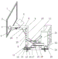
FIG. 1 is a schematic view of the overall structure of the present invention;
FIG. 2 is a schematic view of the connection structure of the deformation bracket and the lead screw of the present invention;
FIG. 3 is a schematic view of the connection structure of the sleeve and the base of the present invention;
fig. 4 is a schematic view of the connection structure of the slide rail and the second stay bar of the present invention.
In the figure: 1. a backboard; 2. an LED light strip; 3. a basket; 4. a power supply box; 5. a solar panel; 6. a first body support; 7. a first stay bar; 8. a limiting hole; 9. a first rotating shaft; 10. a second body support; 11. a second stay bar; 12. a first rotating shaft base; 13. a sleeve; 14. a screw rod; 15. a universal wheel; 16. a deformation support; 17. a third stay bar; 18. a spherical pore; 19. a slide rail; 20. a second rotating shaft base; 21. a storage box; 22. a base; 23. a second rotating shaft; 24. a third rotating shaft; 25. and (4) bolts.
Detailed Description
The technical solutions in the embodiments of the present invention will be described clearly and completely with reference to the accompanying drawings in the embodiments of the present invention, and it is obvious that the described embodiments are only some embodiments of the present invention, not all embodiments. Based on the embodiments in the present invention, all other embodiments obtained by a person skilled in the art without creative work belong to the protection scope of the present invention.
Referring to fig. 1-4, the present invention provides a technical solution: a multifunctional basketball stand comprises a backboard 1, LED lamp strips 2, a basket 3, a power box 4, a solar electric board 5, a first main body support 6, a first support rod 7, a limiting hole 8, a first rotating shaft 9, a second main body support 10, a second support rod 11, a first rotating shaft base 12, a sleeve 13, a lead screw 14, a universal wheel 15, a deformation support 16, a third support rod 17, a spherical hole 18, a sliding rail 19, a second rotating shaft base 20, a storage box 21, a base 22, a second rotating shaft 23, a third rotating shaft 24 and a bolt 25, wherein the basket 3 is fixed at the end part of the first main body support 6, the backboard 1 is arranged between the basket 3 and the first main body support 6, the LED lamp strips 2 are arranged at the edge of the backboard 1, the solar electric board 5 is connected to the top of the first main body support 6, the power box 4 is arranged inside the first main body support 6, and the second main body support 10 are connected with each other through the first rotating shaft 9, meanwhile, the two sides of the first main body bracket 6 are provided with a first support rod 7 through a second rotating shaft 23, the left and right sides of the second main body bracket 10 are provided with a limiting hole 8, the inside of the limiting hole 8 is connected with a bolt 25, the second support rod 11 is fixed on the two sides of the second main body bracket 10 through the second rotating shaft 23, the outer side of the base 22 is provided with 8 sleeves 13, the inside of each sleeve 13 is penetrated with a screw rod 14, the outer side of each screw rod 14 is provided with a deformation bracket 16, a universal wheel 15 is fixed below the deformation bracket 16, the left side of the upper part of the base 22 is fixed with a first rotating shaft base 12, the base 22 and the second main body bracket 10 are connected with each other through the first rotating shaft base 12, the inside of the first rotating shaft base 12 is provided with a first rotating shaft 9, a slide rail 19 is fixed on the upper part of the base 22, and the slide rail 19 and the second support rod 11 in the, and the slide rail 19 of the side is also connected with one end of the third stay bar 17 through the bolt 25, meanwhile, the spherical hole 18 is arranged on both sides of the upper part of the base 22, the second rotating shaft base 20 is fixed on the right side of the upper part of the base 22, the base 22 is connected with the storage box 21 through the second rotating shaft base 20, the third rotating shaft 24 is arranged in the second rotating shaft base 20, and the other end of the third stay bar 17 is fixed on both sides of the storage box 21 through the second rotating shaft 23.
Backboard 1 and basket 3 are fixed connection with first main part support 6, and the edge of backboard 1 bonds and has the LED lamp area 2 of round to maintain original fixed connection between LED lamp area 2 and power supply box 4 and the solar energy electroplax 5 between electric connection backboard 1 and basket 3 and the first main part support 6, guaranteed the firm degree of structure, backboard 1 edge bonds and has the LED lamp area 2 of round to guarantee to have enough sufficient illumination night.
For the welded relation between the upper portion of first main part support 6 and solar energy electroplax 5, and constitute revolution mechanic through first pivot 9 between first main part support 6 and the second main part support 10, and the bilateral symmetry of first main part support 6 is provided with 2 first vaulting poles 7, constitute simultaneously between first vaulting pole 7 lower extreme through bolt 25 and the spacing hole 8 and dismantle mounting structure, and spacing hole 8 is in the equidistant evenly distributed of the both sides of second main part support 10, the revolution mechanic of constituteing has played crucial effect in folding and control height aspect, the dismantlement mounting structure who constitutes between first vaulting pole 7 and bolt 25 and the spacing hole 8 provides the guarantee again for main structure's stability.
Two liang of a set of evenly distributed of sleeve pipe 13 is in the outside of base 22, and be the rotating-structure that the bearing is connected between sleeve pipe 13 and the lead screw 14, and the screw thread trend at lead screw 14 both ends is opposite, and threaded connection between lead screw 14 and the deformation support 16, the tip of lead screw 14 sets up to the ring form simultaneously, bearing structure between sleeve pipe 13 and the lead screw 14 does not influence its rotation when guaranteeing to play fixed action to lead screw 14, the opposite helicitic texture at lead screw 14 both ends can make deformation support 16 play the effect of lift universal wheel 15, the ring form that the tip of lead screw 14 set up can be placed wherein convenient the rotation with the hook.
The upper portion welding of base 22 has 4 slide rails 19, and the dislocation distribution between the slide rail 19 at middle part and the slide rail 19 at edge, and be sliding connection between the tip of slide rail 19 and second vaulting pole 11 and third vaulting pole 17, and the both sides of slide rail 19 set up the round hole column structure that distributes to equidistant, slide rail 19's setting makes second vaulting pole 11 and third vaulting pole 17 convenient fixed to major structure when corresponding the different angle of buckling of major structure, the equidistant round hole column structure that distributes that slide rail 19 both sides set up plays important effect in the fixed of second vaulting pole 11 and third vaulting pole 17 one end.
The working principle is as follows: when the multifunctional basketball stand is used, firstly, the first main body support 6 and the second main body support 10 need to be adjusted to a proper angle according to the requirements of figures 1 and 4, the first main body support 6 is manually lifted or put down to enable the first main body support 6 and the second main body support to relatively rotate through the rotating structure of the first rotating shaft 9 so as to achieve the change of an angle, then the bolt 25 at the end part of the first support rod 7 is fixed at the limiting hole 8 to fix the adjusted angle and position between the first main body support 6 and the second main body support 10, then the second main body support 10 is manually lifted or put down to enable the second main body support 10 to relatively rotate through the rotating structure of the first rotating shaft base 12 and the base 22 so as to achieve the change of the angle and position between the first main body support and the second main body support, in order to fix the adjusted position and angle relationship, the bolt 25 at the end part of the second support rod 11 needs to be fixed in the outer round hole-shaped opening of the, when the storage function is needed, the storage box 21 is only manually lifted to enable the storage box and the second rotating shaft base 20 to rotate relatively through the third rotating shaft 24, after the adjustment is completed, the end parts of the third support rods 17 on the two sides of the storage box are required to be fixed in the circular hole-shaped openings on the outer sides of the sliding rails 19 through the bolts 25, and when an idle basketball is available, the basketball can be placed in the spherical hole 18, so that the injury of players caused by the fact that the basketball rolls to the field at will is avoided;
according to the backboard 1 shown in the figure 1, the circle of LED lamp strip 2 is adhered to the edge of the backboard 1 and forms an electrical connection structure with the power box 4 and the solar panel 5, and the lighting effect can be achieved only by turning on a switch in the power box 4 when the natural color is dark;
as shown in fig. 2 and 3, when the basketball stand needs to be moved, only 4 lead screws 14 need to be rotated simultaneously, and due to the opposite thread structures, the threaded sleeves at the two ends of the deformation support 16 generate relative movement, so that the deformation support 16 is driven to deform, and the universal wheels 15 are retracted.
Although the present invention has been described in detail with reference to the foregoing embodiments, it will be apparent to those skilled in the art that modifications may be made to the embodiments or portions thereof without departing from the spirit and scope of the invention.
Claims (6)
1. The utility model provides a multi-functional basketball stands, includes basket (3), slide rail (19), second pivot base (20) and base (22), its characterized in that: the basket (3) is fixed at the end part of the first main body support (6), the backboard (1) is arranged between the basket (3) and the first main body support (6), the edge of the backboard (1) is provided with the LED lamp strip (2), the top of the first main body support (6) is connected with the solar panel (5), the power box (4) is arranged inside the first main body support (6), the first main body support (6) and the second main body support (10) are connected with each other through the first rotating shaft (9), meanwhile, the first support rods (7) are arranged at two sides of the first main body support (6) through the second rotating shaft (23), the limiting holes (8) are arranged at the left side and the right side of the second main body support (10), the bolts (25) are connected inside the limiting holes (8), and the second support rods (11) are fixed at two sides of the second main body support (10) through the second rotating shaft (23), the outer side of the base (22) is provided with 8 sleeves (13), a lead screw (14) penetrates through the sleeves (13), a deformation support (16) is installed on the outer side of the lead screw (14), universal wheels (15) are fixed below the deformation support (16), a first rotating shaft base (12) is fixed on the left side of the upper portion of the base (22), the base (22) and a second main body support (10) are connected with each other through a first rotating shaft base (12), a first rotating shaft (9) is arranged inside the first rotating shaft base (12), the sliding rail (19) is fixed on the upper portion of the base (22), the sliding rail (19) in the middle portion is connected with a second support rod (11) through a second rotating shaft (23), the sliding rail (19) on the side is connected with one end of a third support rod (17) through a bolt (25), and spherical holes (18) are formed in two sides of the upper portion of the base (22), second pivot base (20) are fixed in the upper portion right side of base (22), and base (22) and storage tank (21) are through second pivot base (20) interconnect to there is third pivot (24) in the inside of second pivot base (20), the other end of third vaulting pole (17) is fixed in the both sides of storage tank (21) through second pivot (23).
2. A multi-functional basketball stand as defined in claim 1, wherein: backboard (1) and basket (3) are fixed connection with first main part support (6), and the edge of backboard (1) bonds has round LED lamp area (2) to electrical connection between LED lamp area (2) and power supply box (4) and solar energy electroplax (5).
3. A multi-functional basketball stand as defined in claim 1, wherein: be the welded relation between the upper portion of first main part support (6) and solar energy electroplax (5), and constitute revolution mechanic through first pivot (9) between first main part support (6) and second main part support (10), and the bilateral symmetry of first main part support (6) is provided with 2 first vaulting poles (7), and first vaulting pole (7) lower extreme passes through to constitute between bolt (25) and spacing hole (8) simultaneously and dismantles the mounting structure, and spacing hole (8) are at the both sides of second main part support (10) equidistant evenly distributed moreover.
4. A multi-functional basketball stand as defined in claim 1, wherein: two liang a set of evenly distributed of sleeve pipe (13) are in the outside of base (22), and be the rotating-structure that the bearing is connected between sleeve pipe (13) and lead screw (14) to the screw trend at lead screw (14) both ends is opposite, and threaded connection between lead screw (14) and deformation support (16) moreover, and the tip of lead screw (14) sets up to the ring form simultaneously.
5. A multi-functional basketball stand as defined in claim 1, wherein: first pivot base (12) are installed in the upper portion welding of base (22), and rotate between base (22) through first pivot base (12) and second main part support (10) and be connected to 2 second vaulting poles (11) are installed to the bilateral symmetry of second main part support (10).
6. A multi-functional basketball stand as defined in claim 1, wherein: the welding of the upper portion of base (22) has 4 slide rails (19), and dislocation distribution between slide rail (19) at middle part and the slide rail (19) at edge to be sliding connection between the tip of slide rail (19) and second vaulting pole (11) and third vaulting pole (17), the both sides of slide rail (19) set up the round hole column structure of equidistant distribution moreover.
Priority Applications (1)
| Application Number | Priority Date | Filing Date | Title |
|---|---|---|---|
| CN201922351291.XU CN211885273U (en) | 2019-12-24 | 2019-12-24 | Multifunctional basketball stand |
Applications Claiming Priority (1)
| Application Number | Priority Date | Filing Date | Title |
|---|---|---|---|
| CN201922351291.XU CN211885273U (en) | 2019-12-24 | 2019-12-24 | Multifunctional basketball stand |
Publications (1)
| Publication Number | Publication Date |
|---|---|
| CN211885273U true CN211885273U (en) | 2020-11-10 |
Family
ID=73293506
Family Applications (1)
| Application Number | Title | Priority Date | Filing Date |
|---|---|---|---|
| CN201922351291.XU Expired - Fee Related CN211885273U (en) | 2019-12-24 | 2019-12-24 | Multifunctional basketball stand |
Country Status (1)
| Country | Link |
|---|---|
| CN (1) | CN211885273U (en) |
Cited By (1)
| Publication number | Priority date | Publication date | Assignee | Title |
|---|---|---|---|---|
| CN112190897A (en) * | 2020-11-13 | 2021-01-08 | 湖南省嘉联文化传媒有限公司 | Simple and easy basketball stands of assembled |
-
2019
- 2019-12-24 CN CN201922351291.XU patent/CN211885273U/en not_active Expired - Fee Related
Cited By (1)
| Publication number | Priority date | Publication date | Assignee | Title |
|---|---|---|---|---|
| CN112190897A (en) * | 2020-11-13 | 2021-01-08 | 湖南省嘉联文化传媒有限公司 | Simple and easy basketball stands of assembled |
Similar Documents
| Publication | Publication Date | Title |
|---|---|---|
| CN207555435U (en) | A kind of gardens multifunctional LED road lamp | |
| CN206647968U (en) | A kind of adjustable solar street lamp | |
| CN107830481A (en) | A kind of solar environment friendly Lawn lamp | |
| CN211885273U (en) | Multifunctional basketball stand | |
| CN207392091U (en) | A kind of municipal administration folding warning sign being convenient for carrying | |
| CN206144241U (en) | Electric power high voltage transmission equipment | |
| CN207168977U (en) | A kind of basketball stands | |
| CN207567684U (en) | A kind of construction warning sign | |
| CN109506192A (en) | A kind of electrical integrated street lamp of solar energy lithium that wind-proof performance is good | |
| CN107945688A (en) | A kind of solar energy outdoor indicating board | |
| CN108679564A (en) | It is a kind of can bidirectional modulation solar energy wall lamp | |
| CN107883321A (en) | A kind of street lamp with elevating function | |
| CN208014263U (en) | A kind of portable power construction warning sign | |
| CN207394695U (en) | A kind of solar environment friendly Lawn lamp | |
| CN207307107U (en) | Basketball stands with lighting device | |
| CN208081786U (en) | A kind of more people's basketball stands of physical education | |
| CN205878014U (en) | Energy -conserving deinsectization street lamp of municipal administration | |
| CN206660519U (en) | A kind of new type solar energy basketball stands | |
| CN207159809U (en) | A kind of Bridge guardrail | |
| CN208804612U (en) | A kind of street lamp of generation of electricity by new energy | |
| CN207230398U (en) | Solar street light | |
| CN207584616U (en) | A kind of solar energy fancy street lamp | |
| CN207094500U (en) | A kind of wind power generation streetlamp | |
| CN215925370U (en) | Automatic rotating quilt airing device based on solar energy | |
| CN213389669U (en) | Landscape bridge |
Legal Events
| Date | Code | Title | Description |
|---|---|---|---|
| GR01 | Patent grant | ||
| GR01 | Patent grant | ||
| CF01 | Termination of patent right due to non-payment of annual fee | ||
| CF01 | Termination of patent right due to non-payment of annual fee |
Granted publication date: 20201110 Termination date: 20211224 |