CN211872176U - Dust collector for carding machine - Google Patents
Dust collector for carding machine Download PDFInfo
- Publication number
- CN211872176U CN211872176U CN202020311918.9U CN202020311918U CN211872176U CN 211872176 U CN211872176 U CN 211872176U CN 202020311918 U CN202020311918 U CN 202020311918U CN 211872176 U CN211872176 U CN 211872176U
- Authority
- CN
- China
- Prior art keywords
- dust
- box
- fixedly connected
- carding machine
- motor
- Prior art date
- Legal status (The legal status is an assumption and is not a legal conclusion. Google has not performed a legal analysis and makes no representation as to the accuracy of the status listed.)
- Active
Links
Images
Landscapes
- Preliminary Treatment Of Fibers (AREA)
Abstract
The utility model discloses a dust collector for carding, including the dust removal case, air exhauster and motor, motor fixed mounting is on the one end lateral wall of dust removal case, the upper end intercommunication of dust removal case is equipped with the feed inlet, the lower extreme intercommunication of dust removal case is equipped with the discharge gate, the sealed dustproof mechanism that is equipped with in feed inlet top, the upper end fixed connection of dustproof mechanism and dust removal case, the lower extreme fixedly connected with dust collection box of dust removal case, the upper end and the discharge gate intercommunication setting of dust collection box, be equipped with filter mechanism in the dust collection box, filter mechanism seals to set up in the discharge gate below, the output shaft end of motor rotates the one end lateral wall setting and the fixedly connected with stirring mechanism that runs through the dust removal case, air exhauster fixed mounting. The utility model discloses not only realized the dust removal effect to the raw and other materials of carding machine processing, the staff of still being convenient for installs and dismantles the filtration in the device.
Description
Technical Field
The utility model relates to a dust removal technical field especially relates to a dust collector for carding machine.
Background
When a carding machine is used for processing raw materials, the raw materials are generally manually and directly put into the carding machine for carding and wound into rolls, and a certain amount of dust and impurities are contained in the raw materials, so that the using effect of a product processed by the carding machine is reduced.
Most of dust removal devices for carding machines used in the market can not effectively remove dust from raw materials processed by the carding machines, and workers are not convenient to install and disassemble a filter structure in the device.
SUMMERY OF THE UTILITY MODEL
The utility model aims at solving among the prior art that dust collector for carding machine mostly can not remove dust to the raw and other materials of carding machine processing effectively and handle, and the staff of being not convenient for installs the phenomenon with dismantling to the filtration in the device, and the dust collector for carding machine that proposes, it has not only realized the dust removal effect to the raw and other materials of carding machine processing, and the staff of still being convenient for installs and dismantles the filtration in the device.
In order to achieve the above purpose, the utility model adopts the following technical scheme:
a dust removing device for a carding machine comprises a dust removing box, an exhaust fan and a motor, wherein the motor is fixedly arranged on one end side wall of the dust removing box, the upper end of the dust removing box is communicated with a feed inlet, the lower end of the dust removing box is communicated with a discharge outlet, a dust preventing mechanism is hermetically arranged above the feed inlet and is fixedly connected with the upper end of the dust removing box, the lower end of the dust removing box is fixedly connected with a dust collecting box, the upper end of the dust collecting box is communicated with the discharge outlet, a filtering mechanism is arranged in the dust collecting box and is hermetically arranged below the discharge outlet, the tail end of an output shaft of the motor rotates to penetrate through one end side wall of the dust removing box and is fixedly connected with a material overturning mechanism, the exhaust fan is fixedly arranged on one end side wall of the dust collecting box, the air inlet end of the exhaust fan is communicated with one end inner wall, the air outlet end of the exhaust fan acts on the motor.
Preferably, dustproof mechanism includes two first magnetic path of fixed connection in dust removal case upper end, the sealed second dust guard that is equipped with in top of feed inlet, the lower extreme of second dust guard is equipped with two spacing grooves that set up with first magnetic path one-to-one, two the equal fixedly connected with second magnetic path in top of spacing groove, two first magnetic path is equallyd divide and is do not inserted and establish in the spacing inslot that corresponds, two first magnetic path is equallyd divide and is do not connected with the second magnetic path magnetism that corresponds, dustproof mechanism's setting has reduced the dust effectively and has passed through the probability that the feed inlet got into the dust removal incasement.
Preferably, the filtering mechanism comprises two sliding rails which are respectively arranged on the opposite inner walls at the two ends of the dust collection box, the two sliding rails are in sliding connection with the same filtering plate, the opposite inner walls at the two ends of the dust collection box are fixedly connected with elastic plug-in units, the movable ends of the two elastic plug-in units are respectively inserted and connected with the lower ends of the filtering plates, and the raw materials processed by the carding machine and dust impurities are effectively filtered and separated through the filtering mechanism.
Preferably, the elastic plug-in comprises a spring column fixedly connected to the inner wall of one end of the dust collection box, a bolt is fixedly connected to the free end of the spring column, the upper end of the bolt is connected with the lower end of the filter plate in an inserting mode, and the elastic plug-in is convenient for workers to install and detach the filter plate.
Preferably, the spring post comprises a telescopic rod, two ends of the telescopic rod are fixedly connected with the inner wall of one end of the dust collection box and one end of the bolt respectively, the telescopic rod is sleeved with a spring, two ends of the spring are fixedly connected with the inner wall of one end of the dust collection box and one end of the bolt respectively, and the spring post is arranged to facilitate up-and-down movement of the bolt.
Preferably, the material turning mechanism comprises a rotating shaft fixedly connected to the tail end of an output shaft of the motor, one end, far away from the motor, of the rotating shaft is rotatably connected to the inner wall of one end of the dust collection box, a plurality of stirring rods are fixedly connected to the rotating shaft, and the material turning mechanism is arranged, so that the dust removal efficiency of the device on raw materials processed by the carding machine is improved.
Compared with the prior art, the beneficial effects of the utility model are that:
1. the utility model discloses a set up dust removal case, air exhauster, motor, feed inlet, discharge gate, dust collection box, first dust guard, first magnetic path, second dust guard, spacing groove and second magnetic path etc. realized the dust removal effect to the raw and other materials of carding machine processing, and then improved the clean and tidy degree of the raw and other materials of carding machine processing to the quality of the raw and other materials of carding machine processing has been improved.
2. The utility model discloses a set up dust removal case, air exhauster, motor, feed inlet, discharge gate, dust collection box, first dust guard, first magnetic path, second dust guard, spacing groove and second magnetic path etc. the staff of being convenient for installs and dismantles the filtration in the device, and then the staff of being convenient for changes the filtration in the device, and wherein the end of giving vent to anger of air exhauster acts on the motor, has carried out the cooling to the motor effectively and has handled to the life of motor has been improved.
Drawings
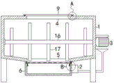
FIG. 1 is a perspective view of a dust removing device for a carding machine according to the present invention;
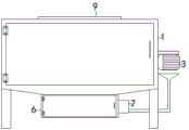
FIG. 2 is a schematic view of an external structure of a dust removing device for a carding machine according to the present invention;
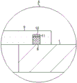
FIG. 3 is an enlarged view of a portion of FIG. 1 at A;
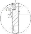
fig. 4 is a partially enlarged view of fig. 1 at B.
In the figure: 1 dust removal case, 2 air blowers, 3 motors, 4 feed inlets, 5 discharge outlets, 6 dust collection cases, 7 first dust guard, 8 first magnetic blocks, 9 second dust guard, 10 spacing grooves, 11 second magnetic blocks, 12 sliding rails, 13 filter plates, 14 spring columns, 15 bolts, 16 rotating shafts and 17 stirring rods.
Detailed Description
The technical solutions in the embodiments of the present invention will be described clearly and completely with reference to the accompanying drawings in the embodiments of the present invention, and it is obvious that the described embodiments are only some embodiments of the present invention, not all embodiments.
Referring to fig. 1-4, a dust removing device for a carding machine comprises a dust removing box 1, an exhaust fan 2 and a motor 3, wherein the motor 3 is fixedly arranged on one end side wall of the dust removing box 1, the upper end of the dust removing box 1 is communicated with a feed inlet 4, the lower end of the dust removing box 1 is communicated with a discharge outlet 5, a dust preventing mechanism is hermetically arranged above the feed inlet 4 and fixedly connected with the upper end of the dust removing box 1, the lower end of the dust removing box 1 is fixedly connected with a dust collecting box 6, the upper end of the dust collecting box 6 is communicated with the discharge outlet 5, a filtering mechanism is arranged in the dust collecting box 6 and hermetically arranged below the discharge outlet 5, the tail end of an output shaft of the motor 3 rotatably penetrates through one end side wall of the dust removing box 1 and is fixedly connected with a material overturning mechanism, the exhaust fan 2 is fixedly arranged on one end, fixed mounting has first dust guard 7 in the inlet end of air exhauster 2, and on the end of giving vent to anger of air exhauster 2 acted on motor 3, need explain, the many support columns of lower extreme fixedly connected with of dust removal case 1, need explain in addition that the end of giving vent to anger of air exhauster 2 is the hopper-shaped setting and acts on motor 3, is the hopper-shaped setting, has increased the active area of air current to motor 3.
Dustproof mechanism includes two first magnetic paths 8 of fixed connection in dust removal case 1 upper end, the sealed second dust guard 9 that is equipped with in top of feed inlet 4, the lower extreme of second dust guard 9 is equipped with two spacing grooves 10 that set up with first magnetic path 8 one-to-one, the equal fixedly connected with second magnetic path 11 in top of two spacing grooves 10, two first magnetic paths 8 are equallyd divide and are do not inserted and establish in the spacing groove 10 that corresponds, two first magnetic paths 8 are equallyd divide and do not be connected with the second magnetic path 11 magnetism that corresponds, dustproof mechanism's setting, the probability that the dust got into dust removal case 1 through feed inlet 4 has been reduced effectively, it needs to explain that, the opposite and magnetic force of one end magnetism of first magnetic path 8 and second magnetic path 11 is moderate, and then both the device of being convenient for the staff take off second dust guard 9 and the device is spacing to second dust guard 9.
The filtering mechanism comprises two sliding rails 12 respectively arranged on the opposite inner walls of two ends of the dust collection box 6, the two sliding rails 12 are connected with a same filtering plate 13 in a sliding way, it needs to be explained that the through holes on the filtering plate 13 only allow the impurities such as dust to pass through, the raw materials processed by the carding machine cannot pass through the filtering plate 13, and further effectively filter and separate the raw materials processed by the carding machine from the impurities such as dust, the opposite inner walls of two ends of the dust collection box 6 are fixedly connected with elastic plug-in units, the movable ends of the two elastic plug-in units are respectively inserted and connected with the lower end of the filtering plate 13, the arrangement of the filtering mechanism effectively filters and separates the raw materials processed by the carding machine from the impurities such as dust, it needs to be explained that as shown in figure 2, box doors are respectively arranged on the outer side walls of one end of the dust collection box 6 and the dust collection box 1 in a sealing way, and, it should be noted that one end of the slide rail 12 close to the door is open, so that the filter plate 13 can be moved out or into the slide rail 12 by the worker.
The elastic plug-in comprises a spring post 14 fixedly connected to the inner wall of one end of the dust collection box 6, a bolt 15 is fixedly connected to the free end of the spring post 14, the upper end of the bolt 15 is inserted into and connected with the lower end of the filter plate 13, the elastic plug-in is arranged to facilitate workers to install and detach the filter plate 13, it is noted that the lower end of the filter plate 13 is provided with two jacks (not shown in the figure) which are arranged in one-to-one correspondence with the bolt 15, the upper ends of the two bolts 15 are respectively inserted into and connected with the corresponding jacks, the spring post 14 comprises a telescopic rod, the two ends of which are respectively fixedly connected with the inner wall of one end of the dust collection box 6 and one end of the bolt 15, a spring is sleeved on the telescopic rod, the two ends of the spring are respectively fixedly connected with the inner wall of one end of the dust collection box 6 and one end, the end of the rotating shaft 16 far away from the motor 3 is rotatably connected to the inner wall of one end of the dust collection box 6, the rotating shaft 16 is fixedly connected with a plurality of stirring rods 17, and the arrangement of the material turning mechanism improves the dust removal efficiency of the device on the raw materials of the carding machine.
In the utility model, when the raw material for processing the carding machine needs to be dedusted, the worker manually takes off the second dustproof plate 9, namely the limiting groove 10 is separated from the first magnetic block 8, after the second dustproof plate 9 is taken off, the raw material to be dedusted is added into the dedusting box 1 through the feed inlet 4, after the feeding is finished, the second dustproof plate 9 is reset, namely the first magnetic block 8 is inserted and connected into the corresponding limiting groove 10, the motor 3 and the exhaust fan 2 are started to work, the motor 3 rotates to drive the rotating shaft 16 to rotate, the rotating shaft 16 rotates to drive the stirring rod 17 to rotate, the stirring rod 17 rotates to turn the added raw material, the exhaust fan 2 works to enable the outside to enter the dedusting box 1 through the clean air flow of the second dustproof plate 9 and to introduce the dust on the raw material in the dedusting box into the dedusting box 6, the stirring rod 17 turns the dust in the dedusting box 1 to be more thoroughly cleaned, after the device finishes working, a worker can open the box door on the dust box 1 to take materials and then send clean raw materials into a carding machine (not shown in the figure) to be processed, the carding machine is the prior art and is not described again, after the materials are taken, the worker can open the box door on the dust box 6 to clean impurities such as dust and the like in the dust box 6, the worker can manually separate two bolts 15 from corresponding jacks by utilizing the elastic property of a spring column 14 to move a filter plate 13 out of a slide rail 12, the removed filter plate 13 is convenient to clean and replace, when the filter plate 13 needs to be installed, the two bolts 15 are moved until the filter plate 13 is convenient to move into the slide rail 12, and then two bolts 15 are loosened to ensure that the two bolts 15 are respectively inserted and connected with the corresponding jacks.
The above, only be the concrete implementation of the preferred embodiment of the present invention, but the protection scope of the present invention is not limited thereto, and any person skilled in the art is in the technical scope of the present invention, according to the technical solution of the present invention and the utility model, the concept of which is equivalent to replace or change, should be covered within the protection scope of the present invention.
Claims (6)
1. A dust removing device for a carding machine comprises a dust removing box (1), an exhaust fan (2) and a motor (3), wherein the motor (3) is fixedly arranged on one end side wall of the dust removing box (1), and is characterized in that the upper end of the dust removing box (1) is communicated with a feed inlet (4), the lower end of the dust removing box (1) is communicated with a discharge outlet (5), a dustproof mechanism is hermetically arranged above the feed inlet (4), the dustproof mechanism is fixedly connected with the upper end of the dust removing box (1), the lower end of the dust removing box (1) is fixedly connected with a dust collecting box (6), the upper end of the dust collecting box (6) is communicated with the discharge outlet (5), a filtering mechanism is arranged in the dust collecting box (6), the filtering mechanism is hermetically arranged below the discharge outlet (5), the tail end of an output shaft of the motor (3) rotates to penetrate through one end side wall of the dust removing box (1) and is fixedly, air exhauster (2) fixed mounting is on the one end lateral wall of dust collection box (6), the inlet end of air exhauster (2) and the one end inner wall intercommunication setting of dust collection box (6), the inlet end internal fixation of air exhauster (2) installs first dust guard (7), the end of giving vent to anger of air exhauster (2) acts on motor (3).
2. The dust collector for carding machine of claim 1, wherein said dust-proof mechanism includes two first magnetic blocks (8) fixedly connected to the upper end of dust-removing box (1), the top of feed inlet (4) is sealed to be equipped with second dust-proof plate (9), the lower end of second dust-proof plate (9) is equipped with two spacing grooves (10) that set up with first magnetic block (8) one-to-one, two the equal fixedly connected with second magnetic block (11) in top of spacing groove (10), two first magnetic block (8) are equallyd divide and are do not inserted and establish and connect in corresponding spacing groove (10), two first magnetic block (8) are equallyd divide and are do not connected with corresponding second magnetic block (11) magnetism.
3. A dust-collecting device for a carding machine, as in claim 1, characterized in that said filtering means comprises two sliding tracks (12) respectively arranged on the opposite inner walls of the two ends of the dust-collecting box (6), two of said sliding tracks (12) being slidably connected with a same filtering plate (13), said dust-collecting box (6) being fixedly connected with elastic plug-in units on the opposite inner walls of the two ends, the movable ends of said elastic plug-in units being respectively connected with the lower ends of the filtering plates (13) by means of plug-in.
4. A dust removing device for a carding machine, as claimed in claim 3, wherein said resilient insert comprises a spring post (14) fixedly attached to the inner wall of one end of the dust box (6), the free end of said spring post (14) being fixedly attached to a pin (15), the upper end of said pin (15) being connected to the lower end of the filter plate (13) by means of an insert.
5. A dust-collecting device for a carding machine, as claimed in claim 4, wherein said spring-loaded column (14) comprises a telescopic rod, the two ends of which are fixedly connected to the inner wall of one end of the dust-collecting box (6) and one end of the bolt (15), respectively, and a spring is sleeved on said telescopic rod, and the two ends of said spring are fixedly connected to the inner wall of one end of the dust-collecting box (6) and one end of the bolt (15), respectively.
6. A dust-collecting apparatus for a carding machine, as claimed in claim 1, wherein said stirring mechanism comprises a shaft (16) fixedly connected to the end of the output shaft of the motor (3), the end of said shaft (16) remote from the motor (3) is rotatably connected to the inner wall of the end of the dust collecting box (6), and a plurality of stirring rods (17) are fixedly connected to said shaft (16).
Priority Applications (1)
| Application Number | Priority Date | Filing Date | Title |
|---|---|---|---|
| CN202020311918.9U CN211872176U (en) | 2020-03-13 | 2020-03-13 | Dust collector for carding machine |
Applications Claiming Priority (1)
| Application Number | Priority Date | Filing Date | Title |
|---|---|---|---|
| CN202020311918.9U CN211872176U (en) | 2020-03-13 | 2020-03-13 | Dust collector for carding machine |
Publications (1)
| Publication Number | Publication Date |
|---|---|
| CN211872176U true CN211872176U (en) | 2020-11-06 |
Family
ID=73258408
Family Applications (1)
| Application Number | Title | Priority Date | Filing Date |
|---|---|---|---|
| CN202020311918.9U Active CN211872176U (en) | 2020-03-13 | 2020-03-13 | Dust collector for carding machine |
Country Status (1)
| Country | Link |
|---|---|
| CN (1) | CN211872176U (en) |
Cited By (2)
| Publication number | Priority date | Publication date | Assignee | Title |
|---|---|---|---|---|
| CN112877820A (en) * | 2021-01-11 | 2021-06-01 | 宫玲 | Carding device in textile production process |
| CN113897711A (en) * | 2021-11-04 | 2022-01-07 | 安徽翰联色纺股份有限公司 | Proofing equipment for colored spun cotton sliver |
-
2020
- 2020-03-13 CN CN202020311918.9U patent/CN211872176U/en active Active
Cited By (3)
| Publication number | Priority date | Publication date | Assignee | Title |
|---|---|---|---|---|
| CN112877820A (en) * | 2021-01-11 | 2021-06-01 | 宫玲 | Carding device in textile production process |
| CN112877820B (en) * | 2021-01-11 | 2023-12-12 | 新疆舜馨纺织有限公司 | Carding device in textile production process |
| CN113897711A (en) * | 2021-11-04 | 2022-01-07 | 安徽翰联色纺股份有限公司 | Proofing equipment for colored spun cotton sliver |
Similar Documents
| Publication | Publication Date | Title |
|---|---|---|
| CN211872176U (en) | Dust collector for carding machine | |
| CN211273913U (en) | Modularization bag collector easy to assemble | |
| CN211840588U (en) | Air draft dust removal mechanism of laser engraving cutting machine | |
| CN208711287U (en) | A kind of purification device of dedusting strainer | |
| CN110694386B (en) | Electric automation control's upset dust type electric appliance cabinet | |
| CN211069386U (en) | High-efficient environment-friendly's dust removal filtration system | |
| CN216395757U (en) | Multifunctional module formula dust remover | |
| CN213555942U (en) | Knitting workshop dust treatment device with two-stage dust removal mechanism | |
| CN217094784U (en) | Dust collection device for coal mine | |
| CN109676188A (en) | The spark cutting machine collecting dust-removing device of foundry | |
| CN212974623U (en) | Industrial waste gas purification device | |
| CN202654835U (en) | Automatic dust collecting device | |
| CN109260847A (en) | A kind of dust-extraction unit | |
| CN214555866U (en) | Dust collection device utilizing industrial dust removal system air source | |
| CN213896109U (en) | Two-for-one twister dust collecting equipment | |
| CN213253507U (en) | High-efficient dust collector is used to spinning machine | |
| CN111577372A (en) | Vehicle-mounted filter cylinder dust removal equipment for tunnel | |
| CN219735980U (en) | Lead core sintering furnace | |
| CN221788530U (en) | Filter device of bag type dust collector | |
| CN217312492U (en) | Road asphalt concrete mixing station raise dust treatment facility | |
| CN217909557U (en) | Filter cartridge dust remover | |
| CN221107480U (en) | Filter cartridge dust remover for dust purification | |
| CN215232858U (en) | Smoke and dust gas collecting and filtering system for vulcanization workshop | |
| CN219801616U (en) | Multifunctional electrical operation cabinet | |
| CN114713529B (en) | Environment-friendly power line treatment equipment for electrical engineering |
Legal Events
| Date | Code | Title | Description |
|---|---|---|---|
| GR01 | Patent grant | ||
| GR01 | Patent grant |