CN211847013U - Ball screw pair of multistage transmission device - Google Patents
Ball screw pair of multistage transmission device Download PDFInfo
- Publication number
- CN211847013U CN211847013U CN202020313123.1U CN202020313123U CN211847013U CN 211847013 U CN211847013 U CN 211847013U CN 202020313123 U CN202020313123 U CN 202020313123U CN 211847013 U CN211847013 U CN 211847013U
- Authority
- CN
- China
- Prior art keywords
- multistage
- sun gear
- screw rod
- gear train
- gear shaft
- Prior art date
- Legal status (The legal status is an assumption and is not a legal conclusion. Google has not performed a legal analysis and makes no representation as to the accuracy of the status listed.)
- Active
Links
Images
Landscapes
- Transmission Devices (AREA)
Abstract
The utility model belongs to the technical field of the supporting high accessory that bears of jacking equipment and specifically relates to a multistage transmission ball screw is vice, including a mount pad, the mount pad be used for install on outside jacking equipment and with external equipment on driving motor supporting, its characterized in that: the top of mount pad is provided with installation circle chamber the top gim peg in installation circle chamber has connect the upper cover the center in installation circle chamber is equipped with a sun gear train, the last lower extreme of sun gear train is worn out in the activity respectively installation circle chamber, the upper end and the multistage lead screw subassembly of triangle of sun gear train link firmly mutually, the lower extreme of sun gear train is supporting with the driving motor on the external equipment, the top and the lift seat of the multistage lead screw subassembly of triangle link firmly. The single-power driving is adopted, and the linkage type triangular multistage lead screw component is adopted to lift together, so that the bearing capacity and the motion stability of the whole multistage lead screw are effectively improved, and the service life of the lead screw is effectively prolonged.
Description
Technical Field
The utility model relates to a supporting high accessory field that bears of jacking equipment, in particular to can realize stabilizing the multistage lead screw institutional advancement that high load lifted, realized going up and down, especially a multistage transmission ball screw is vice.
Background
The existing telescopic system generally adopts hydraulic drive and pneumatic drive, the driving mode generally needs a pneumatic system, a pneumatic press or a hydraulic system and an oil press which are matched with the driving mode correspondingly, so that the volume of the equipment arranged outside the system is large, in the using process, large pieces of matched equipment can generate large execution action noise in the running process, the system configuration is considered from the safety perspective to cause leakage easily, the lifting height can be changed, the self-locking capacity is poor, and certain pollution is realized after the leakage.
Based on the defects of the existing telescopic system, a multi-stage transmission ball screw pair structure is often adopted to replace the traditional telescopic mechanism in the design of many lifting or telescopic equipment at present, and the multi-stage transmission ball screw pair has the advantages of low operation noise, self-locking performance, scalability and the like, so that the multi-stage transmission ball screw pair has good transmission performance when being configured in the lifting or telescopic equipment to operate, and is widely accepted in the market.
However, when the multistage transmission ball screw pair structure runs in lifting or telescopic equipment, due to the fact that the bearing capacity of the multistage transmission ball screw pair structure is poor, the screw failure condition can occur under the heavy load condition, the self-locking capacity of the multistage screw is easy to reduce, and the service life of the multistage transmission ball screw pair structure is also obviously shortened.
SUMMERY OF THE UTILITY MODEL
The utility model discloses a solve the technical scheme that one of above-mentioned technical problem adopted and be: the utility model provides a multistage transmission ball screw is vice, includes a mount pad, the mount pad is used for installing on outside jacking equipment and supporting with the driving motor on the external equipment the top of mount pad is provided with installation circle chamber the top gim peg in installation circle chamber has connect the upper cover the center in installation circle chamber is equipped with a sun gear train, the upper and lower end of sun gear train is worn out in the activity respectively installation circle chamber, the upper end and the multistage lead screw subassembly of triangle of sun gear train link firmly mutually, the lower extreme of sun gear train is supporting with the driving motor on the external equipment, the top and the lift seat of the multistage lead screw subassembly of triangle link firmly.
The multistage screw rod pair is directly installed and fixed on external lifting equipment before use to serve as a lifting execution mechanism and is driven by a driving motor on the external equipment. In the driving process of the driving motor, a sun gear shaft on a sun gear train in the installation round cavity is driven to rotate, so that three pinion shafts are driven to rotate, a planet gear ring is driven to rotate, the rotation of each pinion shaft drives a triangular multistage lead screw assembly to synchronously move to realize lifting, and the running stability of the lifting seat is ensured; the triangular multistage screw rod assembly jointly lifts an object, the lifting capacity is improved to a large extent, the lifting components of the multistage screw rod pairs are effectively dispersed, and the possibility of excessive wear and self-locking failure of the screw rods is reduced.
Preferably, the sun gear train includes one and installs the sun gear shaft at installation circle chamber center be equipped with a plurality of pinion gear shaft along its circumference on the outside wall of sun gear shaft the outside of sun gear shaft the installation circle chamber is coaxial to be provided with a planet wheel ring gear, planet wheel ring gear and each the pinion gear meshes mutually, the upper end activity cartridge of sun gear shaft is in the upper cover centre bore, the lower extreme activity is worn out the mount pad and is connected with the motor shaft of the driving motor on the external equipment, each the lower extreme activity cartridge of pinion gear shaft is in the installation circle chamber bottom is downthehole, the upper end activity is worn out the upper cover and with the multistage lead screw subassembly bottom of triangle links firmly mutually.
The auxiliary gear shaft is driven to rotate through the central rotation of the sun gear shaft, so that the rotating torque is upwards transmitted to the three multi-stage screw rod pairs, the common synchronous lifting of the three multi-stage screw rod pairs is realized, and the single power drives the three powers to synchronously output.
Preferably, a lubricating copper ring is fixedly connected to the outer side wall of the planet gear ring gear, and the outer side wall of the lubricating copper ring is in clearance fit with the inner side wall of the mounting circular cavity.
Set up lubricated copper ring and can guarantee at the planet wheel ring gear along installation circle intracavity rotation when stability is kept, reduce the running friction, the planet wheel ring gear can be effectual the effect that spacing support was radially played to the external diameter of many three pinion gear shafts simultaneously, guarantees the stability of whole sun gear train operation.
Preferably, the triangular multistage screw rod assembly comprises three multistage screw rod pairs which are equal in part along the circumference, the interval angle between the adjacent pinion gear shafts is 120 degrees, the tops of the multistage screw rod pairs are parallel and level and are fixedly connected with the bottom of the lifting seat, and the bottoms of the multistage screw rod pairs are parallel and level and are fixedly connected with the tops of the pinion gear shafts of the sun gear train.
The uniformity of supporting the bottom of the lifting seat and the stability after operation can be guaranteed by the uniform interval distribution of the three multistage screw rod pairs, and the stability of operation in the whole lifting process is guaranteed.
Preferably, the multistage screw pair comprises a screw body, a ball nut is screwed on the outer side wall of the screw body, a jacking auxiliary pipe is sleeved on the outer side wall of the screw body above the ball nut, the lower end of the jacking auxiliary pipe is fixedly connected with the top of the ball nut, and the upper end of the jacking auxiliary pipe is fixedly connected with the bottom of the lifting seat; the inner wall of the jacking auxiliary pipe is matched with the outer wall of the screw rod body.
The ball nut can be driven to lift through the rotation of the screw rod body, so that the jacking auxiliary pipe on the screw rod body can be driven to realize telescopic lifting, and the inner wall of the jacking auxiliary pipe is matched with the outer wall of the screw rod body to ensure the stability in the lifting process and reduce the risk of horizontal swinging.
Preferably, each ball nut of each pinion shaft is fixedly connected through a connecting disc.
Each ball nut is connected into a whole through the connecting disc, so that the synchronism of the three ball nuts in operation is ensured, and the stability of the whole structure is ensured.
The beneficial effects of the utility model are embodied in: the single power is adopted for driving, and the linkage type triangular multistage lead screw assemblies are adopted for lifting together, so that the bearing capacity and the movement stability of the whole multistage lead screw are effectively improved; the periphery of the integral triangular linkage type triangular multistage screw rod assembly is provided with the planetary gear ring to further ensure the stability and the degree of freedom of movement, the lifting or stretching stability is integrally improved, the possibility of self-locking failure of the screw rod is reduced, and the service life of the screw rod is effectively prolonged.
Drawings
In order to more clearly illustrate the embodiments of the present invention or the technical solutions in the prior art, the drawings used in the embodiments or the technical solutions in the prior art will be briefly described below. Throughout the drawings, like elements or components are generally identified by like reference numerals. In the drawings, elements or components are not necessarily drawn to scale.
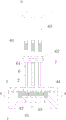
Fig. 1 is a schematic structural diagram of the present invention.
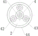
Fig. 2 is a schematic sectional view of the structure from a-a in the installation cavity of fig. 1.
In the figure, 1, a mounting seat; 2. Installing a round cavity; 3. an upper cover; 4. A sun gear train; 41. a sun gear shaft; 42. a pinion shaft; 43. a planet gear ring gear; 44. lubricating the copper ring; 5. A lifting seat; 6. a multi-stage screw pair; 61. a screw rod body; 62. a ball nut; 63. jacking the auxiliary pipe; 7. and (7) connecting the disc.
Detailed Description
Embodiments of the present invention will be described in detail below with reference to the accompanying drawings. The following examples are only for illustrating the technical solutions of the present invention more clearly, and therefore are only examples, and the protection scope of the present invention is not limited thereby.
As shown in fig. 1-2, a multistage transmission ball screw pair, includes a mount pad 1, mount pad 1 is used for installing on external lifting equipment and supporting with the driving motor on the external equipment the top of mount pad 1 is provided with installation round chamber 2 the top gim peg of installation round chamber 2 has connect upper cover 3 the center of installation round chamber 2 is equipped with a sun gear train 4, the upper and lower end of sun gear train 4 is the activity respectively worn out installation round chamber 2, the upper end of sun gear train 4 links firmly with the multistage lead screw subassembly of triangle mutually, the lower extreme of sun gear train 4 is supporting with the driving motor on the external equipment, the top of the multistage lead screw subassembly of triangle links firmly with a lift seat 5.
The multistage screw rod pair 6 is directly installed and fixed on external lifting equipment before use to serve as a lifting execution mechanism and is driven by a driving motor on the external equipment. In the driving process of the driving motor, the driving motor can drive the sun gear shaft 41 on the sun gear train 4 arranged in the circular cavity 2 to rotate, so that the three auxiliary gear shafts 42 are driven to rotate, the planet gear ring 43 also rotates along with the driving motor, and the rotation of each auxiliary gear shaft 42 can drive the triangular multistage screw rod assembly to synchronously move to realize lifting, so that the running stability of the lifting seat 5 is ensured; the triangular multistage screw rod assembly jointly lifts objects, the lifting capacity is improved to a large extent, the lifting components of the multistage screw rod pairs 6 are effectively dispersed, and the possibility of excessive wear and self-locking failure of the screw rods is reduced.
Preferably, the sun gear train 4 includes one installs the sun gear shaft 41 at installation circle 2 center be equipped with a plurality of pinion gear shaft 42 along its circumference on the outside wall of sun gear shaft 41 the outside of sun gear shaft 41 installation circle 2 is coaxial to be provided with a planet wheel ring gear 43, planet wheel ring gear 43 with each pinion gear shaft 42 meshes mutually, the movable cartridge of upper end of sun gear shaft 41 is in the upper cover 3 centre bore, the lower extreme activity is worn out mount pad 1 and is connected with the motor shaft of the driving motor on the external equipment, each the movable cartridge of lower extreme of pinion gear shaft 42 is in installation circle 2 bottom is downthehole, the upper end activity is worn out upper cover 3 and with triangle multistage lead screw subassembly bottom links firmly mutually.
The sun gear shaft 41 rotates in the center to drive the auxiliary gear shaft 42 to rotate, so that the rotating torque is upwards transmitted to the three multi-stage screw rod pairs 6, the three multi-stage screw rod pairs 6 are lifted synchronously, and the single power drives the three powers to output synchronously.
Preferably, a lubricating copper ring 44 is fixedly connected to the outer side wall of the planet gear ring 43, and the outer side wall of the lubricating copper ring 44 is in clearance fit with the inner side wall of the mounting circular cavity 2.
Set up lubricated copper ring 44 and can guarantee to keep stable when planet wheel ring gear 43 along installation circle 2 internal rotations, reduce the running friction, planet wheel ring gear 43 can be effectual the effect that spacing support was radially played to the external diameter of many third pinion gear shafts 42 simultaneously, guarantees the stability of whole sun gear train 4 operation.
Preferably, the triangular multistage screw rod assembly comprises three multistage screw rod pairs 6 which are equal in part along the circumference, the interval angle between the adjacent pinion gear shafts 42 is 120 degrees, the tops of the multistage screw rod pairs 6 are flush and fixedly connected with the bottoms of the lifting seats 5, and the bottoms of the multistage screw rod pairs 6 are flush and fixedly connected with the tops of the pinion gear shafts 42 of the sun gear train 4.
The uniformity of the bottom support of the lifting seat 5 and the stability after operation can be guaranteed by the uniform interval distribution of the three multistage screw rod pairs 6, and the stability of the operation in the whole lifting process is guaranteed.
Preferably, the multistage screw pair 6 comprises a screw body 61, a ball nut 62 is screwed on the outer side wall of the screw body 61, a jacking auxiliary pipe 63 is sleeved on the outer side wall of the screw body 61 above the ball nut 62, the lower end of the jacking auxiliary pipe 63 is fixedly connected with the top of the ball nut 62, and the upper end of the jacking auxiliary pipe is fixedly connected with the bottom of the lifting seat 5; the inner wall of the jacking auxiliary pipe 63 is matched with the outer wall of the screw rod body 61.
The rotation through the lead screw body 61 can drive the ball nut 62 to go up and down to can drive the vice pipe 63 of jacking on it and realize flexible lift, because the inner wall of the vice pipe 63 of jacking with the outer wall of lead screw body 61 cooperatees and can guarantee the stability of lift in-process, reduces the risk of horizontal hunting.
Preferably, the ball nuts 62 of the pinion shafts 42 are fixedly connected by a connecting plate 7.
Each ball nut 62 is connected into a whole through the connecting disc 7, so that the synchronism of the three ball nuts 62 in operation is ensured, and the stability of the whole structure is ensured.
The working description is as follows:
the multistage screw rod pair 6 is directly installed and fixed on external lifting equipment before use to serve as a lifting execution mechanism and is driven by a driving motor on the external equipment. In the driving process of the driving motor, the driving motor can drive the sun gear shaft 41 on the sun gear train 4 arranged in the circular cavity 2 to rotate, so that the three auxiliary gear shafts 42 are driven to rotate, the planet gear ring 43 also rotates along with the driving motor, and the rotation of each auxiliary gear shaft 42 can drive the triangular multistage screw rod assembly to synchronously move to realize lifting, so that the running stability of the lifting seat 5 is ensured; the triangular multistage screw rod assembly jointly lifts objects, the lifting capacity is improved to a large extent, the lifting components of the multistage screw rod pairs 6 are effectively dispersed, and the possibility of excessive wear and self-locking failure of the screw rods is reduced.
The sun gear shaft 41 rotates in the center to drive the auxiliary gear shaft 42 to rotate, so that the rotating torque is upwards transmitted to the three multi-stage screw rod pairs 6, the three multi-stage screw rod pairs 6 are lifted synchronously, and the single power drives the three powers to output synchronously.
The rotation through the lead screw body 61 can drive the ball nut 62 to go up and down to can drive the vice pipe 63 of jacking on it and realize flexible lift, because the inner wall of the vice pipe 63 of jacking with the outer wall of lead screw body 61 cooperatees and can guarantee the stability of lift in-process, reduces the risk of horizontal hunting.
The above embodiments are only used to illustrate the technical solution of the present invention, and not to limit the same; although the present invention has been described in detail with reference to the foregoing embodiments, it should be understood by those skilled in the art that: the technical solutions described in the foregoing embodiments may still be modified, or some or all of the technical features may be equivalently replaced; such modifications and substitutions do not substantially depart from the scope of the embodiments of the present invention, and are intended to be covered by the claims and the specification; to those skilled in the art, any alternative improvements or changes made to the embodiments of the present invention are all within the scope of the present invention.
The parts of the present invention not described in detail are the known techniques of those skilled in the art.
Claims (6)
1. The utility model provides a multistage transmission ball screw is vice, includes a mount pad, the mount pad is used for installing on external lifting equipment and supporting with the driving motor on the external equipment, its characterized in that: the top of mount pad is provided with installation circle chamber the top gim peg in installation circle chamber has connect the upper cover the center in installation circle chamber is equipped with a sun gear train, the last lower extreme of sun gear train is worn out in the activity respectively installation circle chamber, the upper end and the multistage lead screw subassembly of triangle of sun gear train link firmly mutually, the lower extreme of sun gear train is supporting with the driving motor on the external equipment, the top and the lift seat of the multistage lead screw subassembly of triangle link firmly.
2. The ball screw pair of a multistage transmission as claimed in claim 1, wherein: the sun gear train comprises a sun gear shaft arranged at the center of an installation circular cavity, a plurality of pinion gear shafts are arranged on the outer side wall of the sun gear shaft along the circumference of the sun gear shaft, a planet gear ring is coaxially arranged on the installation circular cavity outside the sun gear shaft, the planet gear ring is meshed with the pinion gear shafts, the upper end of the sun gear shaft is movably inserted into the upper cover central hole, the lower end of the sun gear shaft movably penetrates out of the upper cover central hole, the mounting base is connected with a motor shaft of a driving motor on external equipment, and the lower end of the pinion gear shaft movably inserted into the mounting circular cavity bottom hole, the upper end of the pinion gear shaft movably penetrates out of the upper cover and is fixedly connected with the bottom end of the triangular multistage screw rod assembly.
3. The ball screw pair of a multistage transmission as claimed in claim 2, wherein: the outer side wall of the planet gear ring is fixedly connected with a lubricating copper ring, and the outer side wall of the lubricating copper ring is in clearance fit with the inner side wall of the mounting circular cavity.
4. A multistage transmission ball screw set according to claim 3, wherein: the triangular multistage screw rod assembly comprises three multistage screw rod pairs which are equal in part along the circumference, the interval angle between the adjacent pinion gear shafts is 120 degrees, the tops of the multistage screw rod pairs are parallel and level and are fixedly connected with the bottom of the lifting seat, and the bottoms of the multistage screw rod pairs are parallel and level and are fixedly connected with the tops of the pinion gear shafts of the sun gear train.
5. The ball screw pair of a multistage transmission as claimed in claim 4, wherein: the multistage screw rod pair comprises a screw rod body, a ball nut is screwed on the outer side wall of the screw rod body, a jacking auxiliary pipe is sleeved on the outer side wall of the screw rod body above the ball nut, the lower end of the jacking auxiliary pipe is fixedly connected with the top of the ball nut, and the upper end of the jacking auxiliary pipe is fixedly connected with the bottom of the lifting seat; the inner wall of the jacking auxiliary pipe is matched with the outer wall of the screw rod body.
6. The ball screw pair of a multistage transmission as claimed in claim 5, wherein: and the ball nuts of the pinion shafts of the auxiliary wheels are fixedly connected through a connecting disc respectively.
Priority Applications (1)
| Application Number | Priority Date | Filing Date | Title |
|---|---|---|---|
| CN202020313123.1U CN211847013U (en) | 2020-03-13 | 2020-03-13 | Ball screw pair of multistage transmission device |
Applications Claiming Priority (1)
| Application Number | Priority Date | Filing Date | Title |
|---|---|---|---|
| CN202020313123.1U CN211847013U (en) | 2020-03-13 | 2020-03-13 | Ball screw pair of multistage transmission device |
Publications (1)
| Publication Number | Publication Date |
|---|---|
| CN211847013U true CN211847013U (en) | 2020-11-03 |
Family
ID=73132596
Family Applications (1)
| Application Number | Title | Priority Date | Filing Date |
|---|---|---|---|
| CN202020313123.1U Active CN211847013U (en) | 2020-03-13 | 2020-03-13 | Ball screw pair of multistage transmission device |
Country Status (1)
| Country | Link |
|---|---|
| CN (1) | CN211847013U (en) |
Cited By (1)
| Publication number | Priority date | Publication date | Assignee | Title |
|---|---|---|---|---|
| IT202200009269A1 (en) * | 2022-05-06 | 2023-11-06 | Francesco Zanetti | PIT LIFTER |
-
2020
- 2020-03-13 CN CN202020313123.1U patent/CN211847013U/en active Active
Cited By (1)
| Publication number | Priority date | Publication date | Assignee | Title |
|---|---|---|---|---|
| IT202200009269A1 (en) * | 2022-05-06 | 2023-11-06 | Francesco Zanetti | PIT LIFTER |
Similar Documents
| Publication | Publication Date | Title |
|---|---|---|
| CN201383730Y (en) | Oscillating tooth harmonic wave reducing motor | |
| CN211847013U (en) | Ball screw pair of multistage transmission device | |
| CN114718994B (en) | Wind power gear box | |
| CN112762146A (en) | Electric driving wheel with planetary speed reduction transmission | |
| CN217355447U (en) | One-way self-locking device for linear driving mechanism and linear driving mechanism | |
| CN2723116Y (en) | Ceramic polishing machine milling head | |
| CN216299215U (en) | Planet carrier subassembly installation auxiliary platform | |
| CN110723676A (en) | Spiral elevator | |
| CN215626615U (en) | Supporting upright post for operation platform truck | |
| CN218953966U (en) | Force-taking tooth structure of double-steering pump of 5-ton loader | |
| CN216131346U (en) | Sealed oscillating tooth reduction gear of engineering vehicle shaft section | |
| CN215047175U (en) | Platform boarding bridge | |
| CN221565683U (en) | Compact bevel gear ball screw lifter | |
| CN214743071U (en) | Electric driving wheel with planetary speed reduction transmission | |
| CN211778770U (en) | Floating type load-sharing planetary transmission mechanism of engineering machinery | |
| CN219031577U (en) | Mounting structure of tower crane luffing mechanism | |
| CN220393194U (en) | Lifting mechanism for hydraulic lifting platform | |
| CN219101985U (en) | Integral spline screw of speed reducer | |
| CN219263146U (en) | Wet-type braking wheel-side speed reducer assembly for engineering machinery | |
| CN116654796B (en) | Luffing mechanism of tower crane | |
| CN218174523U (en) | Lifting device | |
| CN211951210U (en) | Bearing frame convenient to dismouting | |
| CN101900183A (en) | Construction lifter reducer | |
| CN210307202U (en) | U axle improvement type grinding wheel device | |
| CN221459716U (en) | Motor built-in driving winch |
Legal Events
| Date | Code | Title | Description |
|---|---|---|---|
| GR01 | Patent grant | ||
| GR01 | Patent grant | ||
| PE01 | Entry into force of the registration of the contract for pledge of patent right | ||
| PE01 | Entry into force of the registration of the contract for pledge of patent right |
Denomination of utility model: A ball screw pair of multistage transmission device Effective date of registration: 20221201 Granted publication date: 20201103 Pledgee: China Postal Savings Bank Co.,Ltd. Jining Rencheng District sub branch Pledgor: JINING YICHENG ROLLING PARTS Co.,Ltd. Registration number: Y2022980023398 |