CN211846082U - Controllable intelligent track production line - Google Patents
Controllable intelligent track production line Download PDFInfo
- Publication number
- CN211846082U CN211846082U CN201922258851.7U CN201922258851U CN211846082U CN 211846082 U CN211846082 U CN 211846082U CN 201922258851 U CN201922258851 U CN 201922258851U CN 211846082 U CN211846082 U CN 211846082U
- Authority
- CN
- China
- Prior art keywords
- guide rail
- carriage
- guide rails
- rotary
- positioning
- Prior art date
- Legal status (The legal status is an assumption and is not a legal conclusion. Google has not performed a legal analysis and makes no representation as to the accuracy of the status listed.)
- Active
Links
Images


Abstract
The utility model discloses a controllable intelligent track production line, which comprises a control center control cabinet, a plurality of transverse guide rails, a plurality of vertical guide rails, a plurality of rotary guide rail mechanisms (1) and a running trolley (3), wherein the plurality of transverse guide rails and the plurality of vertical guide rails are distributed in a criss-cross way, and the rotary guide rail mechanisms (1) are arranged at the crisscross connection parts of the transverse guide rails and the vertical guide rails; the running trolley (3) comprises a carriage (31), a driving mechanism and a plurality of gears (37), the driving mechanism is installed in the running trolley (3), the lower end of the driving mechanism is coaxially and fixedly connected with the plurality of gears (37), and a plurality of transverse guide rails and a plurality of vertical guide rails are evenly provided with guide rail racks respectively matched with the gears (37). And the standard unit module is used, so that the cost is low and the use is convenient. The assembly and connection are matched according to production requirements, and the structure is simple and convenient to assemble and disassemble. Centralized control, dynamic resource allocation, high efficiency and energy conservation.
Description
Technical Field
The utility model relates to a controllable intelligent track production line belongs to intelligent track technical field.
Background
With the rapid development of economy in China and the world, the product manufacture is taken as an important economic prop industry, how to lead the production to be efficient and energy-saving is the direction of production development, and intelligent production is the research trend of the industry. The controllable intelligent track production line is manufactured by utilizing the technologies of the existing engineering materials, structural mechanics, connection modes, intelligent control and the like to carry out bold innovation and reasonable design and application, so that the efficient and energy-saving production equipment is realized.
SUMMERY OF THE UTILITY MODEL
The utility model aims to solve the technical problem that overcome prior art's defect, provide a controllable intelligent track production line, arrange into different guide rail circuit according to the nimble collocation of characteristics as required of product production, the operation of work dolly realizes the production requirement on predetermineeing the guide rail, guide rail and work dolly are by control center centralized control, each information collector and actuating mechanism on the production line realize real-time information feedback to control center, control center carries out dynamic configuration, realizes energy-efficient manufacturing. The product can be disassembled and assembled, and can be suitable for various complex occasions.
In order to achieve the purpose, the utility model provides a controllable intelligent track production line, which comprises a control center control cabinet, a plurality of transverse guide rails, a plurality of vertical guide rails, a plurality of rotary guide rail mechanisms and a running trolley, wherein the transverse guide rails and the vertical guide rails are distributed in a criss-cross manner, and the rotary guide rail mechanisms are arranged at the crisscross connection positions of the transverse guide rails and the vertical guide rails;
the running trolley comprises a carriage, a driving mechanism and a plurality of gears, the driving mechanism is installed in the running trolley, the lower end of the driving mechanism is coaxially and fixedly connected with the plurality of gears, and a plurality of transverse guide rails and a plurality of vertical guide rails are evenly provided with guide rail racks matched with the gears respectively.
Preferentially, the transverse guide rail comprises a plurality of straight guide rail mechanisms which are sequentially connected in series end to end along a straight line, each straight guide rail mechanism comprises a straight guide rail chassis and a plurality of straight guide rails, a plurality of straight guide rail accommodating grooves matched with the straight guide rails are transversely formed in the upper surface of the guide rail chassis, and the straight guide rails are fixedly arranged in the straight guide rail accommodating grooves;
the straight guide rail is a cuboid plate, the two long edges of the straight guide rail are provided with guide rail racks in a sawtooth shape, and the straight guide rail chassis is a cuboid plate.
Preferably, the vertical guide rail comprises a plurality of straight guide rail mechanisms which are sequentially connected in series end to end along a straight line.
Preferably, the rotary guide rail mechanism comprises a plurality of arc-shaped guide rails, a rotary positioning disc, a rotary tray, a rotary motor and a rotary tray,
the rotary tray is provided with a circular containing groove for containing the rotary positioning disc, a rotary tray groove for containing the rotary tray is formed in the inner bottom wall of the circular containing groove, a plurality of tooth mouths are formed in the outer edge of the rotary tray and communicated with the circular containing groove, a rotary motor containing groove for containing a rotary motor is formed in the center of the circular containing groove, the rotary motor is fixedly arranged in the rotary motor containing groove, an output shaft of the rotary motor is coaxially and fixedly connected with the rotary positioning disc, the rotary positioning disc is located on the rotary tray, a plurality of arc-shaped containing grooves for containing arc-shaped guide rails are formed in the upper surface of the rotary positioning disc, the plurality of arc-shaped guide rails are fixedly arranged in the plurality of arc-shaped containing grooves, two ends of each arc-shaped guide rail are fixedly connected with one;
rotatory tray appearance is rectangle panel, and rotatory positioning disc appearance is cylindrical, and rotatory tray includes tray spare and a plurality of ball, and during a plurality of ball embedding rotated connection tray spare, the tray spare was the annular, and the arc guide rail appearance is curved panel.
Preferentially, actuating mechanism includes power, communication module, controller and a plurality of motor, and communication module, power, the equal fixed mounting of controller and a plurality of motor are inside the carriage, and outside the equal vertical bottom that passes the carriage of the output shaft of a plurality of motors stretched out the carriage, the equal coaxial fixed connection gear of output shaft of motor, controller and a plurality of motor power supply are given to the power, the signal end and the communication module of controller electric connection motor.
Preferably, the carriage comprises a left carriage and a right carriage, the right end of the left carriage is fixedly connected with the left end of the right carriage, a cavity is formed at the joint of the left carriage and the right carriage, the communication module, the power supply, the controller and the motors are all positioned in the cavity, and the left carriage and the right carriage are combined to form a cuboid with a hollow interior; the running trolley further comprises a positioning lock mechanism and a power supply charging interface, the power supply charging interface is embedded in the outer side wall of the carriage, and the power supply charging interface is electrically connected with a power supply; the positioning locking mechanism comprises a plurality of positioning rods and a plurality of positioning sleeves, the plurality of positioning sleeves are vertically and fixedly arranged on the left side wall in the carriage, the plurality of positioning rods are vertically and fixedly arranged on the right side wall in the carriage, the right ends of the positioning sleeves are provided with positioning clamping grooves matched with the positioning rods, and the left ends of the positioning rods are inserted into the positioning clamping grooves.
Preferably, the running trolley further comprises an emergency button, a display, a plurality of wall barrier sensors, an identifier, a warning lamp post and a standard docking module,
the standard butt joint module, the emergency button and the warning lamp post are fixedly arranged at the top of the carriage, the display is embedded in the outer surface of the carriage, the wall barrier sensors are embedded in the outer side wall of the carriage, the recognizer is embedded in the outer side wall of the carriage, the warning lamp post, the standard butt joint module, the wall barrier sensors, the display and the emergency button are electrically connected with the controller, and the emergency button, the display, the wall barrier sensors, the recognizer and the warning lamp post are electrically connected with the power supply.
Preferably, the rotary rail mechanism comprises two arcuate rails or four arcuate rails.
Preferentially, the control center control cabinet comprises a communication module and a control terminal, and the control terminal is electrically connected with the communication module.
The utility model discloses the beneficial effect who reaches:
1. and the standard unit module is used, so that the cost is low and the use is convenient.
2. The assembly and connection are matched according to production requirements, and the structure is simple and convenient to assemble and disassemble.
3. Centralized control, dynamic resource allocation, high efficiency and energy conservation.
4. The guide rail type operation is adopted, the matching precision is high, and the operation is stable and reliable.
5. The integral type unitized assembly production line mode is more flexible in application occasions.
Drawings
FIG. 1 is a perspective view of the present device;
FIG. 2 is a partial schematic view of the present apparatus;
FIG. 3 is a schematic view of a rotary track mechanism in the present device;
FIG. 4 is an exploded view of the rotary guide track mechanism of the present device;
FIG. 5 is a schematic view of a straight rail mechanism in the present apparatus;
FIG. 6 is a perspective view of the running carriage in the apparatus;
FIG. 7 is a cross-sectional view of the running carriage in the apparatus;
fig. 8 is a functional block diagram of the present apparatus.
Reference in the drawings, 1-a rotary guide rail mechanism; 2-a straight guide rail mechanism; 3, running the trolley; 11-an arc-shaped guide rail; 12-rotating the positioning disc; 13-rotating the first tray; 14-a rotating electrical machine; 15-rotating the tray; 21-straight guide rail chassis; 22-a straight guide rail; 30-emergency button; 31-a compartment; 32-positioning rods; 33-a display; 34-barrier sensors; 35-an identifier; 36-power charging interface; 37-gear; 38-warning lamp post; 39-standard docking module; 41-a communication module; 42-a power supply; 43-a controller; 44-a motor; 45-positioning sleeve.
Detailed Description
The following examples are only for illustrating the technical solutions of the present invention more clearly, and the protection scope of the present invention is not limited thereby.
Example one
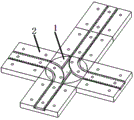
A controllable intelligent track production line comprises a control center control cabinet, a plurality of transverse guide rails, a plurality of vertical guide rails, a plurality of rotary guide rail mechanisms 1 and a running trolley 3, wherein the plurality of transverse guide rails and the plurality of vertical guide rails are distributed in a criss-cross mode, and the rotary guide rail mechanisms 1 are arranged at the staggered connection positions of the transverse guide rails and the vertical guide rails;
the running trolley 3 comprises a carriage 31, a driving mechanism and a plurality of gears 37, the driving mechanism is installed in the running trolley 3, the lower end of the driving mechanism is coaxially and fixedly connected with the plurality of gears 37, and a plurality of transverse guide rails and a plurality of vertical guide rails are uniformly provided with guide rail racks matched with the gears 37 respectively.
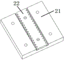
Further, the transverse guide rail comprises a plurality of straight guide rail mechanisms 2, the straight guide rail mechanisms 2 are sequentially connected in series end to end along a straight line, each straight guide rail mechanism 2 comprises a straight guide rail chassis 21 and a plurality of straight guide rails 22, a plurality of straight guide rail accommodating grooves matched with the straight guide rails 22 are transversely formed in the upper surface of the guide rail chassis 21, and the straight guide rails 22 are fixedly arranged in the straight guide rail accommodating grooves;
the straight guide rail 22 is a rectangular plate, the two long sides of the straight guide rail 22 are both provided with saw-toothed guide rail racks, and the straight guide rail chassis 21 is a rectangular plate.
Further, the vertical guide rail comprises a plurality of straight guide rail mechanisms 2, and the straight guide rail mechanisms 2 are sequentially connected in series end to end along a straight line.
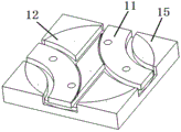
Further, the rotating guide rail mechanism comprises a plurality of arc-shaped guide rails 11, a rotating positioning disc 12, a first rotating tray 13, a rotating motor 14 and a rotating tray 15,
a circular accommodating groove for accommodating a rotary positioning disc 12 is formed in the rotary tray 15, a rotary tray groove for accommodating a rotary tray I13 is formed in the inner bottom wall of the circular accommodating groove, a plurality of tooth mouths communicated with the circular accommodating groove are formed in the outer edge of the rotary tray 15, a rotary motor accommodating groove for accommodating a rotary motor 14 is formed in the center of the circular accommodating groove, the rotary motor 14 is fixedly arranged in the rotary motor accommodating groove, an output shaft of the rotary motor 14 is coaxially and fixedly connected with the rotary positioning disc 12, the rotary positioning disc 12 is positioned on the rotary tray I13, a plurality of arc accommodating grooves for accommodating arc-shaped guide rails 11 are formed in the upper surface of the rotary positioning disc 12, the plurality of arc-shaped guide rails 11 are fixedly arranged in the plurality of arc accommodating grooves, two ends of the arc-shaped guide rails 11 are fixedly connected with a transverse guide rail or a vertical;
the appearance of the rotary tray 15 is a rectangular plate, the appearance of the rotary positioning tray 12 is cylindrical, the first rotary tray 13 comprises a tray piece and a plurality of balls, the plurality of balls are embedded into and rotate to connect the tray piece, the tray piece is annular, and the appearance of the arc-shaped guide rail 11 is an arc-shaped plate.
Further, the driving mechanism comprises a power supply 42, a communication module, a controller 43 and a plurality of motors 44, the communication module, the power supply 42, the controller 43 and the plurality of motors 44 are all fixedly installed inside the carriage 31, output shafts of the plurality of motors 44 vertically penetrate through the bottom of the carriage 31 and extend out of the carriage 31, the output shafts of the motors 44 are all coaxially and fixedly connected with a gear 37, the output shafts of the motors 44 are all in key connection with the gear 37, the power supply 42 supplies power to the controller 43 and the plurality of motors 44, and the controller 43 is electrically connected with a signal end of the motor 44 and the communication module.
Further, the carriage 31 comprises a left carriage and a right carriage, the right end of the left carriage is fixedly connected with the left end of the right carriage, a cavity is formed at the joint of the left carriage and the right carriage, the communication module, the power supply 42, the controller 43 and the motors 44 are all located in the cavity, and the left carriage and the right carriage are combined to form a cuboid with a hollow interior;
the running trolley 3 further comprises a positioning lock mechanism and a power charging interface 36, the power charging interface 36 is embedded into the outer side wall of the carriage 31, and the power charging interface 36 is electrically connected with a power supply 42;
the positioning locking mechanism comprises a plurality of positioning rods 32 and a plurality of positioning sleeves 45, the plurality of positioning sleeves 45 are vertically and fixedly arranged on the left side wall in the carriage 31, the plurality of positioning rods 32 are vertically and fixedly arranged on the right side wall in the carriage 31, the right end of each positioning sleeve 45 is provided with a positioning clamping groove matched with the positioning rods 32, the left ends of the positioning rods 32 are inserted into the positioning clamping grooves, and the positioning rods 32 and the plurality of positioning sleeves 45 are cylindrical rod pieces.
Further, the running carriage 3 comprises an emergency button 30, a display 33, a plurality of wall barrier sensors 34, an identifier 35, a warning lamp post 38 and a standard docking module 39,
the standard docking module 39, the emergency button 30 and the warning lamp post 38 are fixedly arranged at the top of the carriage 31, the display 33 is embedded in the outer surface of the carriage 31, the plurality of barrier sensors 34 are embedded in the outer side wall of the carriage 31, the identifier 35 is embedded in the outer side wall of the carriage 31, the warning lamp post 38, the standard docking module 39, the barrier sensors 34, the display 33 and the emergency button 30 are electrically connected with the controller 43, and the emergency button 30, the display 33, the plurality of barrier sensors 34, the identifier 35 and the warning lamp post 38 are all electrically connected with the power supply 42.
Further, the rotary guide rail mechanism 1 comprises two arc-shaped guide rails 11, the two arc-shaped guide rails 11 are symmetrically distributed on the rotary positioning disc 12, and the two arc-shaped guide rails 11 are communicated with four transverse guide rails and four vertical guide rails.
Further, the control center control cabinet comprises a communication module and a control terminal, and the control terminal is electrically connected with the communication module.
In the device, the power charging interface 36, the gear 37, the rotating motor 14, the power supply 42, the communication module, the controller 43, the motors 44, the emergency button 30, the display 33, the wall barrier sensors 34, the identifier 35, the warning lamp post 38 and the standard docking module 39 are various types which can be adopted in the prior art, and can be selected by a person skilled in the art according to actual needs.
The working principle and the working process of the device are as follows:
the rotary tray 15 and the straight guide rail chassis 21 are fixedly installed on a factory workshop prefabricated platform in the prior art in a bolt connection mode (for example, threaded holes are drilled on the factory floor) or the straight guide rail chassis 21 and the straight guide rail chassis 21 in the transverse guide rail/vertical guide rail are directly spliced and fixedly connected with each other by screws, the rotary motor 14 in the rotary guide rail mechanism 1 is connected into a control center control cabinet by a cable, the arc-shaped guide rail 11 and the straight guide rail 22 on the rotary guide rail are both of a bilateral rack structure, the rotary guide rail is installed on the rotary positioning disc 12 in a threaded connection mode, the straight guide rail 22 is installed on the straight guide rail chassis 21 in a threaded connection mode,
the running trolley is meshed with racks of the arc-shaped guide rail 11 or the straight guide rail 22 through three pairs of moving gears 37 and realizes relative movement, the running trolley comprises a carriage, a positioning locking mechanism, a display, a barrier sensor, an identifier, a power charging interface, a moving gear, a warning lamp post, a standard butt joint module, an emergency button, a communication module, a power supply, a controller and a motor, the running trolley is provided with an independent power supply, the power supply 42 is a storage battery and can realize charging, the running trolley is connected with a control center control cabinet through the communication module to carry out wireless signal exchange, the motion of the running trolley is independently completed by a controller 43 of the running trolley, the carriage is a six-sided rectangular hollow box body and consists of a frame support and a panel, the positioning locking mechanism comprises two convex-concave groups of a positioning rod 32 and a positioning sleeve 45 which are respectively fixed on two side faces in the carriage, the positioning and locking of the carriage are realized, the barrier sensors are respectively arranged at the four corners of the front outer wall and the rear outer wall of the carriage, the position measurement of the front vehicle and the rear vehicle is realized,
the recognizer is a radio frequency recognizer and is arranged on the outer side walls of two side panels of the carriage to realize the recognition effect on radio frequency codes, and the display is a liquid crystal panel and is arranged on the two side panels of the carriage to realize the display effect on information (such as radio frequency codes); the power supply charging interface is a three-hole power supply wiring socket and is arranged below the rear end panel of the compartment body, so that the external connection effect of power supply charging is realized; the warning lamp post is formed by serially connecting red, yellow and green lamps and is arranged at one corner of the upper surface of the carriage to realize the warning function, and the motion gears are three pairs of six gears which are arranged at the bottom of the carriage and are connected with six groups of motors in a key manner; the standard butt joint module is characterized in that a regular matrix cavity (round holes, square holes, hexagonal holes and the like) is formed in the upper surface of the carriage to realize the connection effect of external equipment, the emergency button is a button type electric switch and is installed at the edge of the upper surface of the carriage to realize the power-off effect in emergency, and the communication module is a wireless communication module and is installed in the carriage and powered by a power supply; the controller is an information processing control unit, is arranged in the carriage, is powered by a power supply, and is connected with the recognizer, the display, the positioning locking mechanism, the motor, the emergency button, the warning lamp post and the barrier sensor through cables; the six motors 44 are direct current motors, are respectively arranged at the designated positions of the lower end surface in the carriage and are connected by a motion gear. The running trolley is connected with the control center through the communication module by wireless signals, and control information exchange is realized. The motion of the moving trolley is independently completed by a trolley controller and is connected with a control center through a communication module.
The rotary motor is arranged in a central cavity of the rotary mechanism chassis and is connected with the control center through a cable, the rotary guide rail positioning disc is composed of a retainer and balls, is placed in a groove of the rotary mechanism chassis and is connected with the groove of the rotary tray to realize the relative rotation of the rotary tray, the rotary tray is a circular tray and is placed on the rotary guide rail positioning disc and is connected with the motor in a key connection mode, and the rotary guide rail is composed of a straight guide rail and a quarter circular guide rail which are correspondingly distributed and is arranged on the rotary tray in a threaded connection mode.
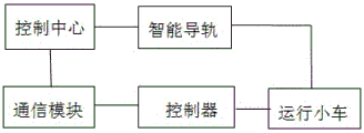
The device can be flexibly matched according to the characteristics of product production as required, different guide rail circuits are arranged, the running trolley runs on a preset guide rail to realize production requirements, the guide rail and the working trolley are controlled in a centralized manner by a control center, each information collector and each executing mechanism on a production line realize real-time information feedback to the control center, a control cabinet of the control center is dynamically configured, the control cabinet of the control center is dynamically configured, and a plurality of programs which can be adopted in the prior art are controlled by software, and detailed description is not carried out in the device. The device realizes efficient and energy-saving production and manufacturing, can be disassembled and assembled, and can be suitable for various complex occasions.
Example two
Different from the first embodiment, the rotating rail mechanism 1 in the present embodiment includes four arc-shaped guide rails 11, and the four arc-shaped guide rails 11 communicate with eight transverse guide rails and eight vertical guide rails in total, and include eight motors 44 and eight gears in the present embodiment.
The utility model has the advantages that:
1. and the standard unit module is used, so that the cost is low and the use is convenient.
2. The soul matching assembly connection is realized according to the production requirement, and the structure is simple and the assembly and disassembly are convenient.
3. Centralized control, dynamic resource allocation, high efficiency and energy conservation.
4. The guide rail type operation is adopted, the matching precision is high, and the operation is stable and reliable.
5. The integral type unitized assembly production line mode is more flexible in application occasions.
The foregoing is only a preferred embodiment of the present invention, and it should be noted that, for those skilled in the art, a plurality of modifications and variations can be made without departing from the technical principle of the present invention, and these modifications and variations should also be considered as the protection scope of the present invention.
Claims (9)
1. A controllable intelligent track production line is characterized by comprising a control center control cabinet, a plurality of transverse guide rails, a plurality of vertical guide rails, a plurality of rotary guide rail mechanisms (1) and a running trolley (3), wherein the plurality of transverse guide rails and the plurality of vertical guide rails are distributed in a criss-cross mode, and the rotary guide rail mechanisms (1) are arranged at the staggered connection positions of the transverse guide rails and the vertical guide rails;
the running trolley (3) comprises a carriage (31), a driving mechanism and a plurality of gears (37), the driving mechanism is installed in the running trolley (3), the lower end of the driving mechanism is coaxially and fixedly connected with the plurality of gears (37), and a plurality of transverse guide rails and a plurality of vertical guide rails are evenly provided with guide rail racks respectively matched with the gears (37).
2. The controllable intelligent track production line as claimed in claim 1, wherein the transverse guide rail comprises a plurality of straight guide rail mechanisms (2), the straight guide rail mechanisms (2) are sequentially connected in series end to end along a straight line, each straight guide rail mechanism (2) comprises a straight guide rail chassis (21) and a plurality of straight guide rails (22), a plurality of straight guide rail accommodating grooves matched with the straight guide rails (22) are transversely formed in the upper surface of the guide rail chassis (21), and the straight guide rails (22) are fixedly arranged in the straight guide rail accommodating grooves;
the straight guide rail (22) is a cuboid plate, the two long sides of the straight guide rail (22) are provided with saw-tooth-shaped guide rail racks, and the straight guide rail chassis (21) is a cuboid plate.
3. A controllable intelligent track production line as claimed in claim 2, wherein the vertical guide rail comprises a plurality of straight guide rail mechanisms (2), and the straight guide rail mechanisms (2) are connected in series with each other end to end along a straight line.
4. A controllable intelligent track production line according to claim 1, wherein the rotating guide rail mechanism comprises a plurality of arc-shaped guide rails (11), a rotating positioning disc (12), a first rotating tray (13), a rotating motor (14) and a rotating tray (15),
a circular containing groove for containing a rotary positioning disc (12) is formed in the rotary tray (15), a rotary tray groove for containing a rotary tray I (13) is formed in the inner bottom wall of the circular containing groove, a plurality of tooth mouths communicated with the circular containing groove are formed in the outer edge of the rotary tray (15), a rotary motor containing groove for containing a rotary motor (14) is formed in the center of the circular containing groove, the rotary motor (14) is fixedly arranged in the rotary motor containing groove, the rotary positioning disc (12) is coaxially and fixedly connected with the output shaft of the rotary motor (14), the rotary positioning disc (12) is positioned on the rotary tray I (13), a plurality of arc containing grooves for containing arc guide rails (11) are formed in the upper surface of the rotary positioning disc (12), a plurality of arc containing grooves for containing arc guide rails (11) are fixedly arranged in the plurality of arc containing grooves, and two ends of the arc guide rails (11) are respectively and fixedly connected with, the control center control cabinet is electrically connected with the rotating motor (14);
rotatory tray (15) appearance is rectangle panel, and rotatory positioning disk (12) appearance is cylindrical, and rotatory tray (13) include tray spare and a plurality of ball, and during a plurality of ball embedding rotated connection tray spare, the tray spare was the annular, and arc guide (11) appearance is curved panel.
5. The controllable intelligent track production line as claimed in claim 1, wherein the driving mechanism comprises a power supply (42), a communication module, a controller (43) and a plurality of motors (44), the communication module, the power supply (42), the controller (43) and the motors (44) are all fixedly installed inside the carriage (31), output shafts of the motors (44) vertically penetrate through the bottom of the carriage (31) and extend out of the carriage (31), output shafts of the motors (44) are all coaxially and fixedly connected with a gear (37), the power supply (42) supplies power to the controller (43) and the motors (44), and the controller (43) is electrically connected with a signal end of the motor (44) and the communication module.
6. The controllable intelligent track production line as claimed in claim 5, wherein the carriage (31) comprises a left carriage and a right carriage, the right end of the left carriage is fixedly connected with the left end of the right carriage, a cavity is formed at the joint of the left carriage and the right carriage, the communication module, the power supply (42), the controller (43) and the motors (44) are all located in the cavity, and the left carriage and the right carriage are combined to form a cuboid with a hollow interior; the running trolley (3) further comprises a positioning lock mechanism and a power charging interface (36), the power charging interface (36) is embedded into the outer side wall of the carriage (31), and the power charging interface (36) is electrically connected with a power supply (42); the positioning locking mechanism comprises a plurality of positioning rods (32) and a plurality of positioning sleeves (45), the plurality of positioning sleeves (45) are vertically and fixedly arranged on the left side wall in the carriage (31), the plurality of positioning rods (32) are vertically and fixedly arranged on the right side wall in the carriage (31), the right ends of the positioning sleeves (45) are provided with positioning clamping grooves matched with the positioning rods (32), and the left ends of the positioning rods (32) are inserted into the positioning clamping grooves.
7. A controllable intelligent track production line as claimed in claim 6, characterized in that the running carriage (3) further comprises an emergency button (30), a display (33), a plurality of wall barrier sensors (34), an identifier (35), a warning light column (38) and a standard docking module (39),
standard butt joint module (39), emergency button (30) and warning light post (38) are fixed to be set up at the top in carriage (31), display (33) are embedded on carriage (31) surface, a plurality of wall barrier sensors (34) are embedded on the lateral wall of carriage (31), recognizer (35) are embedded on the lateral wall of carriage (31), warning light post (38), standard butt joint module (39), wall barrier sensor (34), display (33), emergency button (30) electric connection director (43), emergency button (30), display (33), a plurality of wall barrier sensors (34), recognizer (35), warning light post (38) equal electric connection source (42).
8. A controllable intelligent track production line as claimed in claim 4, characterized in that the rotary guide rail mechanism (1) comprises two arc-shaped guide rails (11) or four arc-shaped guide rails (11).
9. The controllable intelligent track production line as claimed in claim 1, wherein the control center control cabinet comprises a communication module and a control terminal, and the control terminal is electrically connected with the communication module.
Priority Applications (1)
| Application Number | Priority Date | Filing Date | Title |
|---|---|---|---|
| CN201922258851.7U CN211846082U (en) | 2019-12-17 | 2019-12-17 | Controllable intelligent track production line |
Applications Claiming Priority (1)
| Application Number | Priority Date | Filing Date | Title |
|---|---|---|---|
| CN201922258851.7U CN211846082U (en) | 2019-12-17 | 2019-12-17 | Controllable intelligent track production line |
Publications (1)
| Publication Number | Publication Date |
|---|---|
| CN211846082U true CN211846082U (en) | 2020-11-03 |
Family
ID=73215038
Family Applications (1)
| Application Number | Title | Priority Date | Filing Date |
|---|---|---|---|
| CN201922258851.7U Active CN211846082U (en) | 2019-12-17 | 2019-12-17 | Controllable intelligent track production line |
Country Status (1)
| Country | Link |
|---|---|
| CN (1) | CN211846082U (en) |
-
2019
- 2019-12-17 CN CN201922258851.7U patent/CN211846082U/en active Active
Similar Documents
| Publication | Publication Date | Title |
|---|---|---|
| CN112139542A (en) | Power distribution cabinet production is with high-efficient drilling equipment in no dead angle | |
| CN110937345A (en) | Controllable intelligent track production line | |
| CN203779235U (en) | Five axis machining center | |
| CN211846082U (en) | Controllable intelligent track production line | |
| CN201455717U (en) | Safe permanent magnetic chuck | |
| CN215395110U (en) | Overturning trolley for assembling fuel cell engine | |
| CN214603946U (en) | Turning device is used in processing of high definition LED display screen | |
| CN212287544U (en) | Fixed net rack for iron casting machining | |
| CN211167101U (en) | AGV car steering control mechanism | |
| CN215598448U (en) | Wisdom is environmental monitoring device for building site | |
| CN212161115U (en) | Multifunctional model show shelf for architectural design | |
| CN211080934U (en) | Floor lifting device of informatization machine room | |
| CN209924377U (en) | Drilling equipment for interior decoration | |
| CN220792493U (en) | Hydraulic power unit | |
| CN220766248U (en) | Dust-free room gantry robot anti-swing crane | |
| CN210521281U (en) | Intelligent moving vehicle for wheelchair bed | |
| CN212475263U (en) | Production transmission device of direct current screen | |
| CN220934601U (en) | 35Kv or above skid-mounted electric control integrated substation bottom plate | |
| CN218777538U (en) | Electric mould part taking trolley | |
| CN220596751U (en) | Elevator car bottom structure | |
| CN220267328U (en) | Movable lifting rotary stage mechanical device | |
| CN220903350U (en) | Inspection robot | |
| CN212739709U (en) | Multi-station automatic feeding trolley material sheet positioning device | |
| CN212553734U (en) | Multi-angle processing platform is used in outer wallboard production | |
| CN212684016U (en) | Robot integration arm |
Legal Events
| Date | Code | Title | Description |
|---|---|---|---|
| GR01 | Patent grant | ||
| GR01 | Patent grant |