CN211841093U - Double-station pump body machining and fixing tool device - Google Patents
Double-station pump body machining and fixing tool device Download PDFInfo
- Publication number
- CN211841093U CN211841093U CN201921861154.4U CN201921861154U CN211841093U CN 211841093 U CN211841093 U CN 211841093U CN 201921861154 U CN201921861154 U CN 201921861154U CN 211841093 U CN211841093 U CN 211841093U
- Authority
- CN
- China
- Prior art keywords
- fixing
- station
- pump body
- fixing device
- fixed
- Prior art date
- Legal status (The legal status is an assumption and is not a legal conclusion. Google has not performed a legal analysis and makes no representation as to the accuracy of the status listed.)
- Active
Links
Images
Landscapes
- Jigs For Machine Tools (AREA)
- Details Of Reciprocating Pumps (AREA)
Abstract
The utility model discloses a double-station fixed tooling device for processing a pump body, which comprises a frame body, a first fixing device, a second fixing device and a base, wherein a support column is arranged in the middle of the frame body, the frame body is divided into a first fixing station and a second fixing station through the support column, the first fixing device is arranged at the first fixing station through a first through hole, and a first fixing seat is arranged at the bottom of the first fixing station; the second fixing device sets up in the fixed station of second through-hole, and the fixed station bottom of second is equipped with the second fixing base, the utility model discloses a design in fixed frock duplex position can be fixed simultaneously to two pump bodies, has improved the work efficiency of pump body processing, wherein supports the design of the adjustable clamping part of tight device, makes the clamping part can adapt to the pump body of the different shape specifications of centre gripping, has the stable advantage of centre gripping.
Description
Technical Field
The utility model relates to a frock technical field is fixed to the pump body relates to a fixed tool equipment of duplex position pump body processing.
Background
The pump body is the part commonly used in mechanical setting, and after the pump body casting, need process it, for the convenience process the pump body, need fix the pump body, current pump shape difference, then need fix through some specific pump body fixed frock.
However, some existing pump body fixing tools are mostly single-station tools, only a single pump body can be fixed, and along with the increasing of production technology, the number of product processing assembly lines is increased, and the fixing tools for clamping the pump body in a single-station mode cannot meet the processing requirements of the existing product assembly lines.
SUMMERY OF THE UTILITY MODEL
An object of the utility model is to provide a frock device is fixed in duplex position pump body processing for solve above-mentioned technical problem, it is stable to have pump body centre gripping, can carry out the characteristics of the duplex position centre gripping pump body.
The utility model provides a technical problem can adopt following technical scheme to realize:
a double-station fixing tool device for machining a pump body comprises a frame body, a first fixing device, a second fixing device and a base, wherein a support column is arranged in the middle of the frame body, the frame body is divided into a first fixing station and a second fixing station through the support column, the first fixing device is arranged on the first fixing station through a first through hole, and a first fixing seat is arranged at the bottom of the first fixing station; the second fixing device is arranged at the second fixing station through a second through hole, and a second fixing seat is arranged at the bottom of the second fixing station.
Further, the first fixing device comprises a first hydraulic cylinder, a first piston rod connected with one end of the first hydraulic cylinder, and a first clamping portion connected with the other end of the first piston rod.
Further, the first clamping part is used for clamping the pump body, and the first clamping part is further provided with a first abutting device.
Furthermore, the second fixing device comprises a second piston rod connected with one end of the second hydraulic cylinder and a second clamping part connected with the other end of the second piston rod.
Further, the second clamping part is used for clamping the pump body, and the second clamping part is further provided with a second abutting device.
Compared with the prior art, the utility model have following outstanding advantage and effect: the design of fixed frock duplex position more accords with the processing demand of many assembly lines now, can fix two pump bodies simultaneously, has improved the work efficiency of pump body processing, wherein supports the design of the adjustable clamping part of tight device, makes the clamping part can adapt to the pump body of the different shape specifications of centre gripping, has the stable advantage of centre gripping.
The features of the present invention will be apparent from the accompanying drawings and from the detailed description of the preferred embodiments which follows.
Drawings
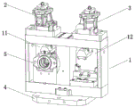
Fig. 1 is a schematic view of the overall structure of the present invention;
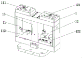
FIG. 2 is a schematic structural view of the frame body of the present invention;
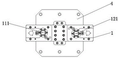
fig. 3 is a top view of the frame body of the present invention;
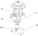
fig. 4 is a schematic structural view of a first fixing device of the present invention;
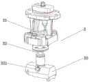
fig. 5 is a schematic structural view of a second fixing device of the present invention;
in the figure: 1. a frame body; 11. a first fixed station; 111. a first through hole; 112. a first fixed seat; 12. a second fixed station; 121. a second through hole; 122. a second fixed seat; 13. a support pillar; 2. a first fixing device; 21. a first hydraulic cylinder; 22. a first piston rod; 23. a first clamping portion; 231. a first abutting device; 3. a second fixing device; 31. a second hydraulic cylinder; 32. a second piston rod; 33. a second clamping portion; 331. a second abutting device; 4. a base; 5. and a pump body.
Detailed Description
In order to make the technical means, creation features, achievement purposes and functions of the present invention easy to understand and understand, the present invention is further explained by combining with the specific drawings.
As shown in fig. 1 to 5, a double-station fixed tooling device for pump body processing comprises a frame body 1, a first fixing device 2, a second fixing device 3 and a base 4, wherein a support column 13 is arranged in the middle of the frame body 1, the support column 13 is used for supporting the frame body 1, the frame body 1 is divided into two fixing stations, namely a first fixing station 11 and a second fixing station 12, through the support column 13, the first fixing device 2 is arranged at the first fixing station 11, and the second fixing device 3 is arranged at the second fixing station 12.
Further, a first through hole 111 is formed in the top of the first fixing station 11, the first fixing device 2 is arranged on the first fixing station 11 through the first through hole 111, a first fixing seat 112 is further arranged at the bottom of the first fixing station 11, the first fixing seat 112 is used for fixedly mounting the pump body 5, and the pump body 5 is clamped and fixed through the cooperation of the first fixing device 2 and the first fixing seat 112 during operation.
Further, a second through hole 121 is formed in the top of the second fixing station 12, the second fixing device 3 is arranged on the second fixing station 12 through the second through hole 121, a second fixing seat 122 is further arranged at the bottom of the second fixing station 12, the second fixing seat 122 is used for fixedly mounting the pump body 5, and the pump body 5 is clamped and fixed through the cooperation of the second fixing device 3 and the second fixing seat 122 during operation.
Further, the first fixing device 2 includes a first piston rod 22 connected between the first hydraulic cylinder 21 and one end of the first hydraulic cylinder 21, and a first clamping portion 23 connected to the other end of the first piston rod 22, when the first fixing device is operated, the first hydraulic cylinder 21 is started to drive the first piston rod 22 to reciprocate, the first piston rod 22 penetrates through the first through hole 111 and is connected with the first clamping portion 23, the first piston rod 22 can drive the first clamping portion 23 to clamp and fasten the pump body 5, the first clamping portion 23 is further provided with a first abutting device 231, the first abutting device 231 is used for adjusting the first clamping portion 23, and the first clamping portion 23 can be adjusted to clamp the pump bodies 5 of different shapes and specifications by rotating the first abutting device 231.
Further, the second fixing device 3 includes a second piston rod 32 connected between the second hydraulic cylinder 31 and one end of the second hydraulic cylinder 31, and a second clamping portion 33 connected to the other end of the second piston rod 32, when the second fixing device is operated, the second hydraulic cylinder 31 is started to drive the second piston rod 32 to reciprocate, the second piston rod 32 penetrates through the second through hole 121 and is connected to the second clamping portion 33, the second piston rod 32 can drive the second clamping portion 33 to clamp and fasten the pump body 5, the second clamping portion 33 is further provided with a second clamping device 331, the second clamping device 331 is used for adjusting the second clamping portion 33, and the second clamping device 331 is rotated to adjust a clamping angle of the second clamping portion 33, so that the second clamping portion 33 can be adapted to clamp pump bodies 5 of different shapes and specifications.
Further, the first hydraulic cylinder 21, the first piston rod 22 and the first clamping portion 23 of the first fixture 2 and the second hydraulic cylinder 31, the second piston rod 32 and the second clamping portion 33 of the second fixture 3 are identical components having the same function.
The utility model discloses an optimal design has adopted the design of the fixed frock in duplex position, more accords with the processing demand of many current assembly lines, can fix simultaneously to two pump bodies, has improved the work efficiency of pump body processing, supports the design of the adjustable clamping part of tight device, makes the clamping part can adapt to the pump body of the different shape specifications of centre gripping, has the stable advantage of centre gripping.
It will be appreciated by those skilled in the art that the invention may be embodied in other specific forms without departing from the spirit or essential characteristics thereof. The embodiments disclosed above are therefore to be considered in all respects as illustrative and not restrictive. All changes which come within the scope of the invention or which are equivalent to the scope of the invention are embraced by the invention.
Claims (5)
1. The utility model provides a fixed tool equipment of duplex position pump body processing, includes frame body (1), first fixing device (2), second fixing device (3) and base (4), its characterized in that: a support column (13) is arranged in the middle of the frame body (1), the frame body (1) is divided into a first fixing station (11) and a second fixing station (12) through the support column (13), the first fixing device (2) is arranged on the first fixing station (11) through a first through hole (111), and a first fixing seat (112) is arranged at the bottom of the first fixing station (11); the second fixing device (3) is arranged at the second fixing station (12) through a second through hole (121), and a second fixing seat (122) is arranged at the bottom of the second fixing station (12).
2. The double-station fixed tooling device for pump body machining according to claim 1, characterized in that: the first fixing device (2) comprises a first hydraulic cylinder (21), a first piston rod (22) connected with one end of the first hydraulic cylinder (21), and a first clamping part (23) connected with the other end of the first piston rod (22).
3. The double-station fixed tooling device for pump body machining according to claim 2, characterized in that: the first clamping portion (23) is used for clamping the pump body (5), and a first abutting device (231) is arranged on the first clamping portion (23).
4. The double-station fixed tooling device for pump body machining according to claim 1, characterized in that: the second fixing device (3) comprises a second hydraulic cylinder (31), a second piston rod (32) connected with one end of the second hydraulic cylinder (31), and a second clamping part (33) connected with the other end of the second piston rod (32).
5. The double-station fixed tooling device for pump body machining according to claim 4, characterized in that: the second clamping portion (33) is used for clamping the pump body (5), and the second clamping portion (33) is provided with a second abutting device (331).
Priority Applications (1)
| Application Number | Priority Date | Filing Date | Title |
|---|---|---|---|
| CN201921861154.4U CN211841093U (en) | 2020-08-11 | 2020-08-11 | Double-station pump body machining and fixing tool device |
Applications Claiming Priority (1)
| Application Number | Priority Date | Filing Date | Title |
|---|---|---|---|
| CN201921861154.4U CN211841093U (en) | 2020-08-11 | 2020-08-11 | Double-station pump body machining and fixing tool device |
Publications (1)
| Publication Number | Publication Date |
|---|---|
| CN211841093U true CN211841093U (en) | 2020-11-03 |
Family
ID=73218032
Family Applications (1)
| Application Number | Title | Priority Date | Filing Date |
|---|---|---|---|
| CN201921861154.4U Active CN211841093U (en) | 2020-08-11 | 2020-08-11 | Double-station pump body machining and fixing tool device |
Country Status (1)
| Country | Link |
|---|---|
| CN (1) | CN211841093U (en) |
-
2020
- 2020-08-11 CN CN201921861154.4U patent/CN211841093U/en active Active
Similar Documents
| Publication | Publication Date | Title |
|---|---|---|
| CN201960389U (en) | Automobile braking hub numerical control vertical lathe fixture | |
| CN102699715B (en) | Clamping device | |
| CN205218599U (en) | Module processing upset anchor clamps about forge hot mould | |
| CN211841093U (en) | Double-station pump body machining and fixing tool device | |
| CN204912529U (en) | Pneumatic flaring ware of copper aluminum pipe spare | |
| CN102205431A (en) | Multi-station processing machine tool for danfoss crank shaft oil hole | |
| CN215700016U (en) | Five-axis machining clamp for steering knuckle of Jetta three-compartment vehicle | |
| CN214488973U (en) | Frock clamp that mould processing milling machine was used | |
| CN210588273U (en) | Auxiliary supporting tool suitable for machining thin-walled parts with different diameters | |
| CN211804886U (en) | Connecting rod both ends head plane processing frock | |
| CN109664129B (en) | Clamp for motor suspension bracket tube beam and machining method | |
| CN206912718U (en) | Electric machine casing machines frock | |
| CN213730197U (en) | Fixture for door frame welding tool | |
| CN212471160U (en) | Mold machining clamp | |
| CN212240154U (en) | Tool equipment | |
| CN216504560U (en) | Volume production anchor clamps of car camshaft rear end machined part | |
| CN214722353U (en) | Special-shaped valve body tool clamp | |
| CN214922540U (en) | Machining center tool clamp for automobile end cone | |
| CN213438370U (en) | Clamp for personalized preformed base station | |
| CN210132289U (en) | Clamp for motor suspension support tubular beam | |
| CN214768434U (en) | Plate bending fixture | |
| CN217413276U (en) | Tool for machining rear axle | |
| CN212683215U (en) | Q4 front and back support mounting hole series machining clamp | |
| CN221110588U (en) | Press mounting device | |
| CN210648672U (en) | Multi-station drill jig |
Legal Events
| Date | Code | Title | Description |
|---|---|---|---|
| GR01 | Patent grant | ||
| GR01 | Patent grant |