CN211840203U - Automatic mechanical perforating machine - Google Patents
Automatic mechanical perforating machine Download PDFInfo
- Publication number
- CN211840203U CN211840203U CN202020129392.2U CN202020129392U CN211840203U CN 211840203 U CN211840203 U CN 211840203U CN 202020129392 U CN202020129392 U CN 202020129392U CN 211840203 U CN211840203 U CN 211840203U
- Authority
- CN
- China
- Prior art keywords
- driving
- punching
- drilling
- hole
- rod
- Prior art date
- Legal status (The legal status is an assumption and is not a legal conclusion. Google has not performed a legal analysis and makes no representation as to the accuracy of the status listed.)
- Expired - Fee Related
Links
Images


Abstract
The utility model relates to an automatic mechanical puncher, the utility model skillfully utilizes a supporting pad to be arranged under a drill bit in the drilling operation, when the drilling operation is carried out, the tight laminating effect between the supporting pad and the metal plate is utilized, so that the metal plate can not generate bulges at the edge of the aperture in the drilling process, and cutting scraps can be smoothly discharged from the circular hole in the supporting pad and can not be attached to the metal plate, the supporting pad of the circular hole with different apertures is suitable for the drilling operation with different apertures, a driving locking device is additionally arranged at the bottom, a driving rod is utilized to compress a driving spring, a limiting rod is moved to a punching table from a limiting groove to realize transposition, and the clamping effect is realized by the matching of the limiting groove and the limiting rod, the utility model has the advantages of skillful structure, convenient and simple use, and perfectly solves the problems of the bulges at the bottom edge of the aperture and the attaching cutting scraps in the drilling process, the drilling efficiency is improved to a great extent, the practicability is high, and the drilling tool is suitable for popularization and use.
Description
Technical Field
The utility model belongs to the technical field of automatic mechanical equipment, especially, relate to an automatic mechanical puncher.
Background
A drill is a general term for machines and apparatuses that leave a cylindrical hole or hole in an object by means of rotary cutting or rotary pressing using a tool harder and sharper than the object. Also known as drills, punches, through-hole machines, and the like. The expected effect is achieved by drilling the precise parts, and the drilling machines comprise a semi-automatic drilling machine and a full-automatic drilling machine, and the cost of human resources is increased; most enterprises consider full-automatic drilling machines as a development direction. With the development of times and the improvement of the drilling technology of the automatic drilling machine, the advantage of drilling the jewelry by adopting the full-automatic drilling machine to drill the watchband of various hardware molds is obvious.
Wherein to mechanical puncher, we need carry out continuous operation of punching on steel or panel beating usually, carry out the in-process that punches automatically to panel beating among the prior art, the panel beating that often has the aperture lower extreme edge of drilling takes place the arch, in addition be exactly at the in-process of drilling, because drilling temperature process, the cutting bits adhesion of production is difficult for droing and be difficult to handle in the position of hole bottom, the use in aperture has brought very big inconvenience and trouble in the panel beating for subsequent, consequently, we need a urgent need an automatic mechanical puncher is used for solving above problem.
SUMMERY OF THE UTILITY MODEL
Not enough to prior art exists, the utility model aims at providing an automatic mechanical puncher for solve the problem of mentioning in the background art.
The above technical purpose of the present invention can be achieved by the following technical solutions:
an automatic mechanical perforating machine comprises a metal plate feeding device and a perforating device, wherein the metal plate feeding device transfers a metal plate to be processed to the perforating device for perforating operation, and is characterized in that the metal plate feeding device comprises a metal plate storage box, two groups of slide rails are arranged on the front side and the rear side of the metal plate storage box, a feeding frame is connected on the slide rails in a transverse sliding manner, the feeding frame is driven by a transverse hydraulic device, a driving lead screw is connected between the two groups of feeding frames in a rotating manner, two groups of movable plates which are arranged at intervals are matched on the driving lead screw in a threaded manner, a limiting rod fixedly connected between the two groups of feeding frames is penetrated through the front side and the rear side of the two groups of movable plates in a sliding manner, one end of the driving lead screw is connected with a driving motor, the lower end of the movable plate is connected with a hydraulic cylinder, the lower end of the hydraulic cylinder is connected with a hydraulic push rod, the lower end of the grabbing table is connected with a vacuum sucker, and the vacuum sucker is connected with a vacuum air pump;
the punching device comprises a punching table connected with the discharge end of the sheet metal feeding device, a drilling machine is connected on the punching table in a vertical sliding manner, the drilling machine is driven by a vertical hydraulic driving device connected to the punching table, the punching table is rotatably connected with a support ring arranged below the drilling machine, the support ring is provided with a plurality of groups of vertical through holes along the circumferential direction, the upper ends of the through holes are in a hexagonal groove body structure, the lower ends of the through holes are in a round hole structure with the radius smaller than that of a hexagonal inscribed circle, the circular hole and the hexagonal inscribed circle are arranged coaxially with a drill bit of the drilling machine, a supporting pad matched with the inner wall of the through hole is movably connected in the through hole, a vertically through circular hole matched with the hole diameter of the drilled hole is formed on different supporting pads, the supporting ring is connected with a driving locking device, so that the supporting rings with different apertures of the driving locking device can be driven to rotate to the position right below the drill bit of the drilling machine and be locked;
the horizontal hydraulic device, the driving motor, the hydraulic cylinder vertical hydraulic driving device and the drilling machine are all connected with the controller, and the controller drives all the components to be matched to complete automatic drilling operation.
Preferably, the drive locking device comprises a plurality of groups of rectangular sleeves which are uniformly distributed along the circumferential direction and are radially connected to the rotating shaft at the bottom of the support ring, the number of the rectangular sleeves is equal to that of the through holes, the rectangular sleeves are internally and radially connected with a drive rod in a sliding manner and are not separated, the drive rod and the rectangular sleeves are internally and vertically connected with a drive spring, the lower end of the drive rod is vertically connected with a rectangular fixed cylinder which is in sliding fit with the bottom surface of the rectangular sleeve and extends downwards, the fixed cylinder is internally and vertically connected with a limiting rod in a sliding manner and is not separated, a vertically arranged pressure spring is connected between the fixed cylinder and the limiting rod, a plurality of groups of limiting grooves which are uniformly distributed along the circumferential direction of the support ring and extend along the radial direction are arranged on the bottom surface of the punching table, one end of the limiting groove, which faces the center of the support ring, is in arc, when the limiting rod is arranged in the corresponding limiting groove, the supporting ring is limited relative to the rotation of the punching table, and one through hole is positioned under the drill bit.
Preferably, the end part of the limiting rod is arc-shaped, and the end part is provided with a plane structure matched with the bottom surface of the limiting groove.
Preferably, the end part of the driving rod is connected with a driving plate, and the driving plate is connected with a plurality of groups of anti-skid rubber particles.
The utility model has the advantages that: the utility model discloses ingenious utilization a supporting pad is arranged in drilling operation under the drill bit, when carrying out drilling operation, utilize the inseparable laminating effect between supporting pad and the panel board, make in the in-process of drilling, the panel board can not produce the arch at the edge in aperture, and the cutting bits can smoothly discharge from the circular port in the supporting pad, can not adhere to on the position of panel board aperture department, and the supporting pad is movable simultaneously, utilizes the supporting pad of the circular port of different apertures to make it be suitable for the drilling operation of different apertures size, and the bottom has increased the drive locking device, utilizes actuating lever compression drive spring, makes the gag lever post move to the punching platform bottom surface from the spacing groove, thereby realizes the transposition, utilizes the cooperation of spacing groove and gag lever post to realize the chucking effect, the utility model discloses the structure is ingenious, and convenient to use is simple, has perfectly solved the problem of the arch at aperture bottom edge and the attached cutting bits in the drilling process, the drilling efficiency is greatly improved, the subsequent process of aperture treatment is saved, the practicability is high, and the drilling tool is suitable for popularization and use.
Drawings
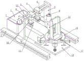
Fig. 1 is a perspective view of the present invention.
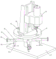
Fig. 2 is a front view perspective two of the present invention.
Fig. 3 is a front view of the present invention.
Fig. 4 is a perspective view of the punching apparatus of the present invention.
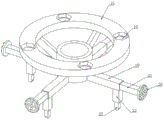
Fig. 5 is a three-dimensional structure diagram of the middle support ring and the connection part thereof.
Fig. 6 is a three-dimensional structure diagram of the supporting pad used in cooperation with the middle supporting ring of the present invention.
Figure 7 is a cross-sectional view of the support ring and its attachment portion of the present invention.
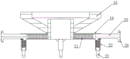
Fig. 8 is a structural diagram of the middle bottom limiting groove of the present invention.
In the figure, 1, a sheet storage box; 2. a slide rail; 3. a feeding frame; 4. driving a lead screw; 5. moving the plate; 6. a restraining bar; 7. a drive motor; 8. a hydraulic cylinder; 9. a hydraulic push rod; 10. a grabbing table; 11. a vacuum chuck; 12. a vacuum air pump; 13. a punching table; 14. a drilling machine; 15. a support ring; 16. a through hole; 17. a support pad; 18. a circular hole; 19. a rectangular sleeve; 20. a drive rod; 21. a drive spring; 22. a fixed cylinder; 23. a limiting rod; 24. a pressure spring; 25. a limiting groove; 26. and (4) anti-skid rubber particles.
Detailed Description
The following detailed description of the embodiments of the present invention will be made with reference to the accompanying drawings.
The first embodiment, with reference to the accompanying drawings 1-8, is an automatic mechanical hole puncher, comprising a sheet metal loading device and a hole punching device, wherein the sheet metal loading device transfers a sheet metal to be processed to the hole punching device for hole punching operation, and is characterized in that the sheet metal loading device comprises a sheet metal storage box 1, a plurality of groups of sheet metals to be processed are placed in the sheet metal storage box 1, two sets of slide rails 2 are arranged on the front and back sides of the sheet metal storage box 1, a feeding frame 3 is transversely and slidably connected to the slide rails 2, a hydraulic pushing device for driving the feeding frame 3 to transversely move is connected to the feeding frame 3 through the transverse hydraulic device driving slide rails 2, the transverse hydraulic device is generally realized by adopting a hydraulic rod to cooperate with a hydraulic push rod 9, in the prior art, a numerical control machine is generally adopted to control and drive the feeding frame to determine the driving stroke, a driving lead screw 4 is rotatably connected between the two sets of feeding frames 3, the punching machine is characterized in that two groups of moving plates 5 which are arranged at intervals are matched on the driving screw rod 4 in a threaded manner, two groups of limiting rods 6 which are fixedly connected between the two groups of upper material racks 3 are arranged on the front and back sides of the two groups of moving plates 5 in a sliding manner in a penetrating manner, the two groups of limiting rods 6 play a role in limiting the rotation of the moving plates 5, one end of the driving screw rod 4 is connected with a driving motor 7, the driving motor 7 rotates to drive the two groups of moving plates 5 to reciprocate in the longitudinal direction simultaneously, so that the longitudinal position of a metal plate is changed, and the metal plate is suitable for different punching positions, the lower end of the moving plate 5 is connected with a hydraulic cylinder 8, the lower end of the hydraulic cylinder 8 is connected with a hydraulic push rod 9, the hydraulic cylinder 8 is connected with a hydraulic pump, the hydraulic pump is connected with an oil cylinder, the hydraulic pump drives the hydraulic, the lower end of the grabbing table 10 is connected with a vacuum sucker 11, the vacuum sucker 11 is connected with a vacuum air pump 12, after the hydraulic push rod 9 pushes downwards to a grabbing position, the vacuum air pump 12 works to pump air in the vacuum sucker 11, and therefore grabbing is achieved on the plate, and the feeding and discharging effects are achieved;
the punching device comprises a punching table 13 connected with the discharge end of the sheet metal feeding device, the punching table 13 is firmly pressed on a current drilling operation position through a hydraulic push rod 9, the punching table 13 is connected with a drilling machine 14 along a vertical sliding way, a drill bit on the drilling machine 14 can be replaced, the drilling machine 14 is driven by a vertical hydraulic driving device connected on the punching table 13, the drilling machine 14 performs vertical drilling operation through the vertical hydraulic driving device, the punching table 13 is rotatably connected with a support ring 15 arranged below the drilling machine 14, the upper surface of the support ring 15 is flush with the upper surface of the punching table 13 for supporting the sheet metal, the support ring 15 is circumferentially provided with a plurality of groups of vertical through holes 16, the upper end of each through hole 16 is of a hexagonal groove body structure, and the lower end of each through hole is of a circular hole structure with a radius smaller than the radius of a hexagonal inscribed circle, the circular hole and the hexagonal inscribed circle are coaxially arranged with a drill bit of the drilling machine 14, that is, along with the rotation of the support ring 15 on the punching table 13, the position of the through hole 16 in the support ring 15 can rotate to the position under the drill bit, so that the drill bit can smoothly escape from the support ring 15, the through hole 16 is internally and movably connected with a support pad 17 matched with the inner wall of the through hole 16, different circular holes 18 which are vertically through and matched with the hole diameter of the drilled hole are formed in the support pad 17, the support pad 17 is also hexagonal at the last time, and is of a lower-layer circular structure, so that the support pad 17 can be smoothly clamped in the through hole 16, when the drilled hole is drilled, the drill bit smoothly performs the drilling operation through the through hole 16, the support ring 15 is connected with a driving locking device, and the requirement of driving the locking device that the support pads 17 with different hole diameters rotate, drive locking device locks supporting pad 17 on the position under the 14 drill bits of drilling machine, ensure the accuracy of drilling, because of the existence of supporting pad 17, when carrying out the drilling operation, drilling machine 14 is after the panel drilling, through supporting pad 17, at this moment, supporting pad 17 can place the panel and produce the arch in drilling process edge, the cutting bits can be discharged from the round hole structure in supporting pad 17 simultaneously, even if adhere to on supporting pad 17, it can to take out the clearance with supporting pad 17, it can not leave over the cutting bits on the panel to have guaranteed, supporting pad 17 can be provided with the general type, when carrying out the drilling of supporting pad 17 in required aperture, it can to change supporting pad 17 of the round hole structure of corresponding aperture size;
horizontal hydraulic means, driving motor 7, the vertical hydraulic drive device of 8 pneumatic cylinders and drilling machine 14 all be connected with the controller, it accomplishes the automatic operation of punching to satisfy the cooperation of controller drive each part, the controller embeds there are time sequence generator and trigger, ensure that the controller carries out the work of the control of different parts according to the programming, the design here is prior art, just no longer give unnecessary details, the controller is through horizontal hydraulic means, driving motor 7, the work of pneumatic cylinder 8 is adjusted the drilling position on the panel metal plate, then, the vertical hydraulic drive device that driving drilling machine 14 connects drills, when needing to beat the multiple row hole, then change the drilling position through the controller can.
In the second embodiment, on the basis of the first embodiment, with reference to fig. 1 to 8, the driving and locking device includes a plurality of sets of rectangular sleeves 19 uniformly distributed along the circumferential direction and radially connected to the rotating shaft at the bottom of the supporting ring 15, the number of the rectangular sleeves 19 is equal to the number of the through holes 16, a driving rod 20 is slidably connected in the rectangular sleeve 19 along the radial direction and is not separated from the supporting ring, in order to meet the requirement that the driving rod 20 is not separated from the rectangular sleeve 19, only a limiting frame is connected to the end of the rectangular sleeve 19, a driving spring 21 is connected between the driving rod 20 and the rectangular sleeve 19, the lower end of the driving rod 20 is vertically connected to a rectangular fixed cylinder 22 which is slidably matched with the bottom surface of the rectangular sleeve 19 and extends downward, the driving rod 20 moves in a vertical through sliding groove formed in the lower end of the rectangular sleeve 19, and a limiting rod 23 is vertically slidably connected in the fixed cylinder 22, a pressure spring 24 which is vertically arranged is connected between the inside of the fixed cylinder 22 and the limiting rod 23, a plurality of groups of limiting grooves 25 which are uniformly distributed along the circumferential direction of the supporting ring 15 and extend along the radial direction are arranged on the bottom surface of the punching table 13, the limiting rods 23 are always propped against the limiting grooves 25 by the pressure spring 24 so as to limit the rotation of the supporting ring 15, one end of each limiting groove 25, which faces the center of the supporting ring 15, is in arc transition with the bottom surface of the punching table 13, the plurality of groups of limiting grooves 25 are respectively matched with the limiting rods 23, so that when the limiting rods 23 are arranged in the corresponding limiting grooves 25, the rotation of the supporting ring 15 relative to the punching table 13 is limited, one through hole 16 is positioned under a drill bit, when a plurality of groups of driving rods 20 are pushed to move towards the central direction, the limiting rods 23 are separated from the arc transition connected with the limiting grooves 25 and then arranged on the bottom surface of the, the adjustment of the position is performed so that the through-hole 16 and the support pad 17 of different hole diameters are placed directly below the drilling machine 14.
In the third embodiment, on the basis of the second embodiment, with reference to fig. 1 to 8, the end of the limiting rod 23 is arc-shaped, and the end is provided with a planar structure matched with the bottom surface of the limiting groove 25, so that the limiting rod 23 can be smoothly separated from the limiting groove 25, and when the limiting rod is matched with the bottom surfaces of the limiting groove 25 and the punching table 13, the clamping effect is remarkable due to the existence of the planar structure.
In the fourth embodiment, on the basis of the second embodiment, with reference to fig. 1 to 8, the end of the driving rod 20 is connected to a driving plate, and the driving plate is connected to a plurality of sets of anti-slip rubber particles 26 to prevent a user from slipping off the hand when using the device.
The utility model discloses when using, the controller is through horizontal hydraulic means, driving motor 7, the work of pneumatic cylinder 8 comes to adjust the position on the panel beating, make it and drilling position phase-match of drilling machine 14, wherein horizontal hydraulic means promotes to realize the ascending displacement of horizontal direction between work or material rest 3 and the guide rail, driving motor 7 drives the rotation of lead screw and makes movable plate 5 carry out the ascending position change of longitudinal direction, the change of vertical position is realized to the hydraulic pump that connects through controller pneumatic cylinder 8, when drilling position on earth, the controller drives vertical hydraulic drive device and carries out the operation of punching, in the in-process of driling, because the existence of supporting pad 17, after drilling machine 14 drilled the panel beating, through supporting pad 17, at this moment, supporting pad 17 can place the panel beating and produce protrudingly in drilling process in the edge, the cutting bits can be discharged from the round hole structure in supporting pad 17 simultaneously, even if the drill bit is attached to the supporting pad 17, the supporting pad 17 can be taken out for cleaning, cutting scraps cannot be left on a metal plate, the supporting pad 17 can be set to be general, when the supporting pad 17 with the required aperture is drilled, the supporting pad 17 with the circular hole structure with the corresponding aperture can be replaced, in order to switch the supporting pads 17 with different circular hole apertures, at the moment, when a plurality of groups of driving rods 20 are pushed to move towards the central direction, the limiting rods 23 are separated from the limiting grooves 25 in the arc transition connected with the limiting grooves 25 and then are placed on the bottom surface of the punching table 13, so that the supporting ring 15 can smoothly rotate, the position is adjusted, the through holes 16 and the supporting pads 17 with different apertures are changed and are placed under the drilling machine 14, then the driving rods 20 are loosened, the limiting rods 23 return to the limiting grooves 25 under the action of the springs, the clamping work of the supporting ring 15, and restoring to the initial position.
The above description is only a preferred embodiment of the present invention, and should not be taken as limiting the invention, and any modifications, equivalent replacements, improvements, etc. made within the spirit and principle of the present invention should be included in the protection scope of the present invention.
Claims (4)
1. An automatic mechanical punching machine comprises a metal plate feeding device and a punching device, wherein the metal plate feeding device transfers a metal plate to be processed to the punching device for punching operation, and is characterized in that the metal plate feeding device comprises a metal plate storage box (1), two groups of slide rails (2) are arranged on the front side and the rear side of the metal plate storage box (1), the slide rails (2) are transversely and slidably connected with a feeding frame (3), the feeding frame (3) is driven by a transverse hydraulic device, a driving lead screw (4) is rotatably connected between the two groups of feeding frames (3), two groups of moving plates (5) which are arranged at intervals are matched on the driving lead screw (4) in a threaded manner, a limiting rod (6) fixedly connected between the two groups of feeding frames (3) penetrates through the front side and the rear side of the two groups of moving plates (5) in a sliding manner, one end of the driving lead screw is connected with a driving motor (7), the lower end of the moving plate (5) is connected with a hydraulic cylinder (8), the lower end of the hydraulic cylinder (8) is connected with a hydraulic push rod (9), the lower end of the hydraulic push rod (9) is connected with a grabbing table (10), the lower end of the grabbing table (10) is connected with a vacuum sucker (11), and the vacuum sucker (11) is connected with a vacuum air pump (12);
the punching device comprises a punching table (13) connected with the discharge end of the sheet metal feeding device, the punching table (13) is connected with a drilling machine (14) in a vertical sliding manner, the drilling machine (14) is driven by a vertical hydraulic driving device connected to the punching table (13), the punching table (13) is rotatably connected with a support ring (15) arranged below the drilling machine (14), the support ring (15) is provided with a plurality of groups of vertical through holes (16) along the circumferential direction, the upper end of each through hole (16) is of a hexagonal groove body structure, the lower end of each through hole (16) is of a round hole structure of which the radius is smaller than that of a hexagonal inscribed circle, the round hole and the hexagonal inscribed circle are coaxially arranged with a drill bit of the drilling machine (14), the through hole (16) is internally and movably connected with a support pad (17) matched with the inner wall of the through hole (16), and different support pads (17) are provided with vertical through round holes (18) matched with the hole, the supporting ring (15) is connected with a driving locking device, so that the supporting pads (17) with different aperture sizes of the driving locking device can be driven to rotate to the position right below the drill bit of the drilling machine (14) and be locked;
the horizontal hydraulic device, the driving motor (7), the hydraulic cylinder (8), the vertical hydraulic driving device and the drilling machine (14) are all connected with the controller, and the controller drives all the components to be matched to complete automatic drilling operation.
2. The automatic mechanical perforating machine according to claim 1, wherein the driving locking device comprises a plurality of groups of rectangular sleeves (19) which are uniformly distributed along the circumferential direction and are radially connected to the rotating shaft at the bottom of the supporting ring (15), the number of the rectangular sleeves (19) is equal to that of the through holes (16), a driving rod (20) is slidably connected in the rectangular sleeves (19) along the radial direction and is not separated, a driving spring (21) is connected in the driving rod (20) and the rectangular sleeves (19), the lower end of the driving rod (20) is vertically connected with a rectangular fixed cylinder (22) which is slidably matched with the bottom surface of the rectangular sleeves (19) and extends downwards, a limiting rod (23) is slidably connected in the fixed cylinder (22) vertically and is not separated, and a vertically arranged pressure spring (24) is connected between the fixed cylinder (22) and the limiting rod (23), the utility model discloses a drill bit, including support ring (15), punching platform (13), limiting groove (25) that have the multiunit along support ring (15) circumference equipartition and along radial extension on the bottom surface of punching platform (13), limiting groove (25) towards the one end at support ring (15) center and punching platform (13) bottom surface arc transition, the multiunit limiting groove (25) respectively with gag lever post (23) phase-match, when satisfying gag lever post (23) and arranging corresponding spacing groove (25) in, support ring (15) are restricted for the rotation of punching platform (13), and one of them through-hole (16) are in under the drill bit.
3. The automatic mechanical punch according to claim 2, wherein the end of the limiting rod (23) is arc-shaped and has a planar structure matching with the bottom surface of the limiting groove (25).
4. The automatic mechanical punch according to claim 2, wherein the end of the drive rod (20) is connected to a drive plate to which sets of non-slip rubber particles (26) are attached.
Priority Applications (1)
| Application Number | Priority Date | Filing Date | Title |
|---|---|---|---|
| CN202020129392.2U CN211840203U (en) | 2020-01-20 | 2020-01-20 | Automatic mechanical perforating machine |
Applications Claiming Priority (1)
| Application Number | Priority Date | Filing Date | Title |
|---|---|---|---|
| CN202020129392.2U CN211840203U (en) | 2020-01-20 | 2020-01-20 | Automatic mechanical perforating machine |
Publications (1)
| Publication Number | Publication Date |
|---|---|
| CN211840203U true CN211840203U (en) | 2020-11-03 |
Family
ID=73232105
Family Applications (1)
| Application Number | Title | Priority Date | Filing Date |
|---|---|---|---|
| CN202020129392.2U Expired - Fee Related CN211840203U (en) | 2020-01-20 | 2020-01-20 | Automatic mechanical perforating machine |
Country Status (1)
| Country | Link |
|---|---|
| CN (1) | CN211840203U (en) |
Cited By (2)
| Publication number | Priority date | Publication date | Assignee | Title |
|---|---|---|---|---|
| CN114851397A (en) * | 2022-04-29 | 2022-08-05 | 河南新华五岳抽水蓄能发电有限公司 | Vertical high-side wall excavation pre-splitting pore-forming rapid positioning device and positioning method thereof |
| CN116141077A (en) * | 2023-02-07 | 2023-05-23 | 扬州市强胜电气有限公司 | Perforating device that building engineering used |
-
2020
- 2020-01-20 CN CN202020129392.2U patent/CN211840203U/en not_active Expired - Fee Related
Cited By (3)
| Publication number | Priority date | Publication date | Assignee | Title |
|---|---|---|---|---|
| CN114851397A (en) * | 2022-04-29 | 2022-08-05 | 河南新华五岳抽水蓄能发电有限公司 | Vertical high-side wall excavation pre-splitting pore-forming rapid positioning device and positioning method thereof |
| CN116141077A (en) * | 2023-02-07 | 2023-05-23 | 扬州市强胜电气有限公司 | Perforating device that building engineering used |
| CN116141077B (en) * | 2023-02-07 | 2023-12-15 | 扬州市强胜电气有限公司 | Perforating device that building engineering used |
Similar Documents
| Publication | Publication Date | Title |
|---|---|---|
| CN211840203U (en) | Automatic mechanical perforating machine | |
| KR20210059061A (en) | Punching mold device | |
| CN211415473U (en) | Automatic perforating machine | |
| CN111085704A (en) | Circulating punching equipment for customized disc-shaped metal parts | |
| KR20080094128A (en) | Apparatus for manufacturing grouting pipe | |
| CN219254191U (en) | Brake disc perforating device | |
| CN213163217U (en) | High-efficient perforating device of metal work piece | |
| CN110961688B (en) | Clamp center hole drilling machine | |
| CN210256528U (en) | Semi-automatic multi-row perforating machine | |
| CN211030305U (en) | Puncher is used in production of antiskid shoe-pad | |
| CN109986106B (en) | Pneumatic double-head perforating machine | |
| CN211941213U (en) | Universal hole plugging and air guide plate punching device for PCB | |
| CN112405048A (en) | Mechanism for continuously punching side wall of metal steel pipe | |
| CN112676883A (en) | Hardware processing drilling equipment | |
| CN104493234A (en) | Multi-station drilling equipment | |
| CN218964086U (en) | Drilling equipment is used in steel products production | |
| CN220127637U (en) | Double-end drilling equipment of adjustable pitch of hole | |
| CN215790360U (en) | Plastic pipe perforating machine | |
| CN209811314U (en) | Milling device for machining adjustable wrench | |
| CN111002389A (en) | Universal hole plugging and air guide plate punching device for PCB | |
| CN216326546U (en) | Positioning equipment for manual drilling machine | |
| CN217046815U (en) | Perforating equipment for wooden door processing | |
| CN217571173U (en) | Multi-machine-position tapping device | |
| CN218557257U (en) | Plastic pipe perforating device | |
| CN215356269U (en) | Efficient multi-head drilling machine |
Legal Events
| Date | Code | Title | Description |
|---|---|---|---|
| GR01 | Patent grant | ||
| GR01 | Patent grant | ||
| CF01 | Termination of patent right due to non-payment of annual fee |
Granted publication date: 20201103 Termination date: 20220120 |
|
| CF01 | Termination of patent right due to non-payment of annual fee |