CN211825153U - Be used for soil monitoring sampling mechanism - Google Patents
Be used for soil monitoring sampling mechanism Download PDFInfo
- Publication number
- CN211825153U CN211825153U CN202020555377.4U CN202020555377U CN211825153U CN 211825153 U CN211825153 U CN 211825153U CN 202020555377 U CN202020555377 U CN 202020555377U CN 211825153 U CN211825153 U CN 211825153U
- Authority
- CN
- China
- Prior art keywords
- rod
- plate
- fixed
- sampling mechanism
- sampling
- Prior art date
- Legal status (The legal status is an assumption and is not a legal conclusion. Google has not performed a legal analysis and makes no representation as to the accuracy of the status listed.)
- Expired - Fee Related
Links
- 230000007246 mechanism Effects 0.000 title claims abstract description 71
- 238000005070 sampling Methods 0.000 title claims abstract description 46
- 239000002689 soil Substances 0.000 title claims abstract description 43
- 238000012544 monitoring process Methods 0.000 title claims abstract description 26
- 230000003028 elevating effect Effects 0.000 claims abstract description 11
- 230000008878 coupling Effects 0.000 claims description 4
- 238000010168 coupling process Methods 0.000 claims description 4
- 238000005859 coupling reaction Methods 0.000 claims description 4
- 239000000956 alloy Substances 0.000 claims description 3
- 229910045601 alloy Inorganic materials 0.000 claims description 3
- 230000009471 action Effects 0.000 description 4
- 238000010586 diagram Methods 0.000 description 3
- 238000004458 analytical method Methods 0.000 description 1
- 230000009286 beneficial effect Effects 0.000 description 1
- 230000008859 change Effects 0.000 description 1
- 238000012512 characterization method Methods 0.000 description 1
- 238000005516 engineering process Methods 0.000 description 1
- 238000009434 installation Methods 0.000 description 1
- 238000002360 preparation method Methods 0.000 description 1
- 238000013441 quality evaluation Methods 0.000 description 1
Images


Landscapes
- Sampling And Sample Adjustment (AREA)
- Investigation Of Foundation Soil And Reinforcement Of Foundation Soil By Compacting Or Drainage (AREA)
Abstract
The utility model discloses a be used for soil monitoring sampling mechanism, including collecting mechanism, moving mechanism, it installs to collect the mechanism both sides moving mechanism still includes sampling mechanism, elevating system, sampling mechanism sets up inside collecting mechanism, elevating system sets up the sampling mechanism top. The utility model discloses a set up elevating system, the depth of fall of artifical manual control drill bit can control the sampling depth well, and through setting up sampling mechanism, the auger rod can drive soil continuously and enter into the collection case for a large amount of soil can once be got to the device, is used for the monitoring of a plurality of indexes of soil sample, has improved the practicality of device.
Description
Technical Field
The utility model relates to a soil monitoring technology field especially relates to and is used for soil monitoring sampling mechanism.
Background
Soil environment monitoring means that the environment quality (or pollution degree) and the change trend thereof are determined by measuring representative values of factors affecting the soil environment quality. Soil monitoring generally refers to soil environment monitoring, and generally comprises technical contents of distribution sampling, sample preparation, analysis methods, result characterization, data statistics, quality evaluation and the like. Soil need use sampling device sample, but current sampling device adopts the sampler barrel sample mostly, and some local soil are harder, and the sampler barrel is hardly stretched into and is taken a sample in the soil to can not control the sample depth well, once can only bore a small amount of soil, the sample volume is less, can not satisfy the monitoring to a plurality of projects of soil environment, and the practicality is relatively poor.
SUMMERY OF THE UTILITY MODEL
An object of the utility model is to provide a be used for soil monitoring sampling mechanism, it stretches into in the soil easily, can bore and get a large amount of soil to well control the sampling depth degree, improved the practicality of device.
The utility model discloses a following technical scheme realizes above-mentioned purpose:
be used for soil monitoring sampling mechanism, including collecting mechanism, moving mechanism, it installs to collect the mechanism both sides moving mechanism still includes sampling mechanism, elevating system, sampling mechanism sets up inside collecting mechanism, elevating system sets up the sampling mechanism top.
Preferably, the collecting mechanism comprises a shell, a collecting box, a box door, a first clamping plate, a second clamping plate and an inserting rod, the collecting box is fixed inside the shell, the box door is arranged on two sides of the shell, the second clamping plate is fixed on the side face of the box door, the first clamping plate is arranged above the second clamping plate, and the inserting rod is arranged on the first clamping plate.
Preferably, the moving mechanism comprises a mounting box, an electric push rod, a connecting plate and a moving wheel, wherein the electric push rod is fixed inside the mounting box, the connecting plate is arranged below the electric push rod, and the moving wheel is arranged below the connecting plate.
Preferably, the sampling mechanism comprises a protection box, a motor, a coupler, an auger rod and a drill bit, wherein the motor is fixed inside the protection box, the coupler is arranged below the protection box, the auger rod is fixed below the coupler, and the drill bit is fixed below the auger rod.
Preferably, elevating system includes first lifter plate, telescopic link, first spring, hemisphere, rotor plate, threaded rod, thread bush, handle, first lifter plate top is fixed with the telescopic link, the quantity of telescopic link is two, the telescopic link outside is provided with first spring, two be provided with between the telescopic link the hemisphere, install the hemisphere top the rotor plate, the rotor plate top is fixed with the threaded rod, the threaded rod outside is provided with the thread bush, the threaded rod top is fixed with the handle.
Preferably, elevating system includes hemisphere, rotor plate, threaded rod, thread bush, handle, second riser plate, guide bar, second spring, stopper, be provided with on the second riser plate the guide bar, the quantity of guide bar is two, install on the guide bar the second spring, the guide bar below is fixed with the stopper, second riser plate top is provided with the hemisphere, install the hemisphere top the rotor plate, the rotor plate top is fixed with the threaded rod, the threaded rod outside is provided with the thread bush, the threaded rod top is fixed with the handle.
Preferably, the guide rod is welded with the limiting block, and the limiting block is made of hard alloy.
Compared with the prior art, the beneficial effects of the utility model are as follows:
1. by arranging the sampling mechanism, the auger rod can continuously drive soil to enter the collecting box, so that the device can drill a large amount of soil at one time, and the practicability of the device is improved;
2. through setting up elevating system, the depth of fall of artifical manual control drill bit can control the sampling depth well.
Drawings
In order to more clearly illustrate the embodiments of the present invention or the technical solutions in the prior art, the drawings needed to be used in the description of the embodiments or the prior art will be briefly described below, it is obvious that the drawings in the following description are only some embodiments of the present invention, and for those skilled in the art, other drawings can be obtained according to these drawings without inventive exercise.
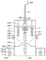
Fig. 1 is a schematic structural diagram of the soil monitoring and sampling mechanism of the present invention;
FIG. 2 is a front view of the soil monitoring and sampling mechanism of the present invention;
fig. 3 is a schematic view of a first internal structure of the soil monitoring and sampling mechanism of the present invention;
fig. 4 is a schematic diagram of a second internal structure of the soil monitoring and sampling mechanism of the present invention;
fig. 5 is a schematic structural diagram of a hemisphere used in the soil monitoring and sampling mechanism of the present invention.
The reference numerals are explained below:
1. a collection mechanism; 101. a housing; 102. a collection box; 103. a box door; 104. a first clamping plate; 105. a second clamping plate; 106. inserting a rod; 2. a moving mechanism; 201. mounting a box; 202. an electric push rod; 203. a connecting plate; 204. a moving wheel; 3. a sampling mechanism; 301. a protection box; 302. a motor; 303. a coupling; 304. a screw rod; 305. a drill bit; 4. a lifting mechanism; 401. a first lifter plate; 402. a telescopic rod; 403. a first spring; 404. a hemisphere; 405. a rotating plate; 406. a threaded rod; 407. a threaded sleeve; 408. a handle; 409. a second lifter plate; 410. a guide bar; 411. a second spring; 412. and a limiting block.
Detailed Description
In the description of the present invention, it is to be noted that, unless otherwise explicitly specified or limited, the terms "mounted," "connected," and "connected" are to be construed broadly, and may be, for example, fixedly connected, detachably connected, or integrally connected; can be mechanically or electrically connected; they may be connected directly or indirectly through intervening media, or they may be interconnected between two elements. The specific meaning of the above terms in the present invention can be understood by those of ordinary skill in the art through specific situations.
The present invention will be further explained with reference to the accompanying drawings:
example 1
As shown in fig. 1, fig. 2, fig. 3 and fig. 5, the soil monitoring and sampling mechanism comprises a collecting mechanism 1 and a moving mechanism 2, wherein the moving mechanism 2 is installed on two sides of the collecting mechanism 1, the soil monitoring and sampling mechanism further comprises a sampling mechanism 3 and a lifting mechanism 4, the sampling mechanism 3 is arranged inside the collecting mechanism 1, and the lifting mechanism 4 is arranged above the sampling mechanism 3.
The collecting mechanism 1 comprises a casing 101, a collecting box 102, a box door 103, a first clamping plate 104, a second clamping plate 105 and an inserting rod 106, wherein the collecting box 102 is fixed inside the casing 101, the box door 103 is arranged on two sides of the casing 101, the second clamping plate 105 is fixed on the side surface of the box door 103, the first clamping plate 104 is arranged above the second clamping plate 105, and the inserting rod 106 is arranged on the first clamping plate 104; the moving mechanism 2 comprises a mounting box 201, an electric push rod 202, a connecting plate 203 and a moving wheel 204, wherein the electric push rod 202 is fixed inside the mounting box 201, the connecting plate 203 is arranged below the electric push rod 202, and the moving wheel 204 is arranged below the connecting plate 203; the sampling mechanism 3 comprises a protection box 301, a motor 302, a coupler 303, an auger rod 304 and a drill bit 305, wherein the motor 302 is fixed inside the protection box 301, the coupler 303 is arranged below the protection box 301, the auger rod 304 is fixed below the coupler 303, and the drill bit 305 is fixed below the auger rod 304; the lifting mechanism 4 comprises a first lifting plate 401, telescopic rods 402, first springs 403, hemispheres 404, a rotating plate 405, a threaded rod 406, threaded sleeves 407 and a handle 408, the telescopic rods 402 are fixed above the first lifting plate 401, the number of the telescopic rods 402 is two, the first springs 403 are arranged on the outer sides of the telescopic rods 402, the hemispheres 404 are arranged between the two telescopic rods 402, the rotating plate 405 is installed above the hemispheres 404, the threaded rod 406 is fixed above the rotating plate 405, the threaded sleeves 407 are arranged on the outer sides of the threaded rods 406, and the handle 408 is fixed above the threaded rods 406.
In the above structure: when the device is used, the device is moved to a corresponding position through the moving wheel 204, the electric push rod 202 is controlled to shrink, the electric push rod 202 shrinks to drive the moving wheel 204 to ascend until the moving wheel 204 completely enters the installation box 201, the motor 302 is started, the motor 302 drives the auger rod 304 and the drill bit 305 to rotate through the coupler 303, the handle 408 is rotated in the forward direction, the handle 408 drives the threaded rod 406 to rotate, the threaded rod 406 descends under the action of the threaded sleeve 407, the threaded rod 406 drives the first lifting plate 401 to descend, the telescopic rod 402 and the first spring 403 are stretched, the auger rod 304 and the drill bit 305 are driven by the first lifting plate 401 to descend, the auger rod 304 extends into soil, the soil enters the collection box 102 under the action of the auger rod 304, the control device recovers to the original position after sampling is finished, the inserting rod 106 is taken down, and the collected soil can be taken out by opening the box door 103 through the second clamping plate.
Example 2
As shown in fig. 1, 2, 4, and 5, the difference between the embodiment 2 and the embodiment 1 is that the first lifting plate 401, the telescopic rod 402, and the first spring 403 are replaced by a second lifting plate 409, a guide rod 410, a second spring 411, and a stop block 412, the guide rod 410 is welded to the stop block 412, the stop block 412 is made of hard alloy, the moving wheel 204 is completely received in the mounting box 201, the motor 302 is started, the motor 302 drives the auger rod 304 and the drill bit 305 to rotate through the coupler 303, the handle 408 rotates the threaded rod 406, the threaded rod 406 descends under the action of the threaded sleeve 407, the threaded rod 406 drives the second lifting plate 409 to descend, the second spring 411 is compressed, the auger rod 304 and the drill bit 305 descend under the second lifting plate 409, the auger rod 304 extends into the soil, the soil enters the collection box 102 under the action of the auger rod 304, the control device returns to the original position after sampling, the inserted rod 106 is taken down, and the collected soil can be taken out by opening the box door 103 through the second clamping plate 105.
The foregoing illustrates and describes the principles, general features, and advantages of the present invention. It will be understood by those skilled in the art that the present invention is not limited to the above embodiments, and that the foregoing embodiments and descriptions are provided only to illustrate the principles of the present invention without departing from the spirit and scope of the present invention.
Claims (7)
1. A be used for soil monitoring sampling mechanism, including collecting mechanism (1), moving mechanism (2), it installs to collect mechanism (1) both sides moving mechanism (2), its characterized in that: still include sampling mechanism (3), elevating system (4), sampling mechanism (3) set up collect inside mechanism (1), elevating system (4) set up sampling mechanism (3) top.
2. The sampling mechanism for soil monitoring of claim 1, wherein: the collecting mechanism (1) comprises a shell (101), a collecting box (102), a box door (103), a first clamping plate (104), a second clamping plate (105) and an inserted rod (106), wherein the collecting box (102) is fixed inside the shell (101), the box door (103) is arranged on two sides of the shell (101), the second clamping plate (105) is fixed on the side face of the box door (103), the first clamping plate (104) is arranged above the second clamping plate (105), and the inserted rod (106) is installed on the first clamping plate (104).
3. The sampling mechanism for soil monitoring of claim 1, wherein: the moving mechanism (2) comprises a mounting box (201), an electric push rod (202), a connecting plate (203) and a moving wheel (204), wherein the electric push rod (202) is fixed inside the mounting box (201), the connecting plate (203) is installed below the electric push rod (202), and the moving wheel (204) is installed below the connecting plate (203).
4. The sampling mechanism for soil monitoring of claim 1, wherein: sampling mechanism (3) are including guard box (301), motor (302), shaft coupling (303), auger rod (304), drill bit (305), guard box (301) inside is fixed with motor (302), guard box (301) below is provided with shaft coupling (303), shaft coupling (303) below is fixed with auger rod (304), auger rod (304) below is fixed with drill bit (305).
5. The sampling mechanism for soil monitoring of claim 1, wherein: elevating system (4) include first lifter plate (401), telescopic link (402), first spring (403), hemisphere (404), rotor plate (405), threaded rod (406), thread bush (407), handle (408), first lifter plate (401) top is fixed with telescopic link (402), the quantity of telescopic link (402) is two, telescopic link (402) outside is provided with first spring (403), two be provided with between telescopic link (402) hemisphere (404), install hemisphere (404) top rotor plate (405), rotor plate (405) top is fixed with threaded rod (406), the threaded rod (406) outside is provided with thread bush (407), threaded rod (406) top is fixed with handle (408).
6. The sampling mechanism for soil monitoring of claim 1, wherein: the lifting mechanism (4) comprises a hemisphere (404), a rotating plate (405), a threaded rod (406), a threaded sleeve (407), a handle (408), a second lifting plate (409), a guide rod (410), a second spring (411) and a limiting block (412), the second lifting plate (409) is provided with the guide rods (410), the number of the guide rods (410) is two, the guide rod (410) is provided with the second spring (411), the lower part of the guide rod (410) is fixed with the limiting block (412), the hemisphere (404) is arranged above the second lifting plate (409), the rotating plate (405) is arranged above the hemisphere (404), the threaded rod (406) is fixed above the rotating plate (405), the threaded sleeve (407) is arranged on the outer side of the threaded rod (406), and the handle (408) is fixed above the threaded rod (406).
7. The sampling mechanism for soil monitoring of claim 6, wherein: the guide rod (410) is welded with the limiting block (412), and the limiting block (412) is made of hard alloy.
Priority Applications (1)
| Application Number | Priority Date | Filing Date | Title |
|---|---|---|---|
| CN202020555377.4U CN211825153U (en) | 2020-04-15 | 2020-04-15 | Be used for soil monitoring sampling mechanism |
Applications Claiming Priority (1)
| Application Number | Priority Date | Filing Date | Title |
|---|---|---|---|
| CN202020555377.4U CN211825153U (en) | 2020-04-15 | 2020-04-15 | Be used for soil monitoring sampling mechanism |
Publications (1)
| Publication Number | Publication Date |
|---|---|
| CN211825153U true CN211825153U (en) | 2020-10-30 |
Family
ID=73141608
Family Applications (1)
| Application Number | Title | Priority Date | Filing Date |
|---|---|---|---|
| CN202020555377.4U Expired - Fee Related CN211825153U (en) | 2020-04-15 | 2020-04-15 | Be used for soil monitoring sampling mechanism |
Country Status (1)
| Country | Link |
|---|---|
| CN (1) | CN211825153U (en) |
Cited By (3)
| Publication number | Priority date | Publication date | Assignee | Title |
|---|---|---|---|---|
| CN112355914A (en) * | 2020-11-17 | 2021-02-12 | 湖南富而康科贸新材料有限公司 | Surface treatment device for manufacturing metal doors and windows |
| CN113029651A (en) * | 2021-03-09 | 2021-06-25 | 南京林业大学 | Hydraulic deep soil sampler |
| CN113832010A (en) * | 2021-09-29 | 2021-12-24 | 孙晓彤 | Soil microorganism detects collector |
-
2020
- 2020-04-15 CN CN202020555377.4U patent/CN211825153U/en not_active Expired - Fee Related
Cited By (3)
| Publication number | Priority date | Publication date | Assignee | Title |
|---|---|---|---|---|
| CN112355914A (en) * | 2020-11-17 | 2021-02-12 | 湖南富而康科贸新材料有限公司 | Surface treatment device for manufacturing metal doors and windows |
| CN113029651A (en) * | 2021-03-09 | 2021-06-25 | 南京林业大学 | Hydraulic deep soil sampler |
| CN113832010A (en) * | 2021-09-29 | 2021-12-24 | 孙晓彤 | Soil microorganism detects collector |
Similar Documents
| Publication | Publication Date | Title |
|---|---|---|
| CN211825153U (en) | Be used for soil monitoring sampling mechanism | |
| CN210090074U (en) | Soil detection uses quick sampling device | |
| CN210572293U (en) | Soil detection device convenient to equipment | |
| CN212159109U (en) | Soil environment monitoring drilling sampling device convenient to use | |
| CN213148372U (en) | A soil testing equipment for being directed at deep soil detects | |
| CN214309612U (en) | Highway engineering is supervised with sampling device that fetches earth | |
| CN208313620U (en) | A kind of soil testing assemblies | |
| CN112113795A (en) | Heavy metal contaminated soil analysis sampling device | |
| CN218847678U (en) | Soil environment monitoring and sampling device suitable for different soil qualities | |
| CN208984382U (en) | Ground sampler in a kind of geotechnical engineering | |
| CN111504690A (en) | Surface soil sampling device for soil detection | |
| CN215811726U (en) | Soil sampler for highway engineering | |
| CN215573887U (en) | Geotechnical engineering reconnaissance sampling device | |
| CN216012778U (en) | Soil sampling device for environmental detection | |
| CN214667813U (en) | Soil collector for forestry | |
| CN112629948B (en) | Acid rain monitoring sampling device for environmental monitoring | |
| CN212722107U (en) | Ecological agriculture and forestry soil detection sampling device | |
| CN212722122U (en) | Soil collection system convenient to clearance | |
| CN213091215U (en) | Data acquisition device for big data processing | |
| CN212539710U (en) | Sampling device based on soil nitrogen measurement | |
| CN211347458U (en) | Rock-soil analysis sampling head | |
| CN207662653U (en) | Earth boring auger device and earth boring auger for soil sampling | |
| CN219511570U (en) | Environment monitoring device with good wind resistance | |
| CN216524909U (en) | Mineral geology sampler with sample collection function | |
| CN217211499U (en) | A convenient sampling device for soil organic carbon detects |
Legal Events
| Date | Code | Title | Description |
|---|---|---|---|
| GR01 | Patent grant | ||
| GR01 | Patent grant | ||
| CF01 | Termination of patent right due to non-payment of annual fee |
Granted publication date: 20201030 |