CN211821527U - Camera convenient to dismantle and install - Google Patents
Camera convenient to dismantle and install Download PDFInfo
- Publication number
- CN211821527U CN211821527U CN201922385096.9U CN201922385096U CN211821527U CN 211821527 U CN211821527 U CN 211821527U CN 201922385096 U CN201922385096 U CN 201922385096U CN 211821527 U CN211821527 U CN 211821527U
- Authority
- CN
- China
- Prior art keywords
- connecting sleeve
- camera
- support rod
- base
- bracing piece
- Prior art date
- Legal status (The legal status is an assumption and is not a legal conclusion. Google has not performed a legal analysis and makes no representation as to the accuracy of the status listed.)
- Active
Links
Images


Landscapes
- Accessories Of Cameras (AREA)
Abstract
The utility model discloses a camera convenient to dismantle and installation belongs to camera technical field, the on-line screen storage device comprises a base, the bottom in the base outside is provided with articulated seat, and the base has first bracing piece through articulated seat swing joint, the inboard bottom of first bracing piece is provided with the shrinkage pool, and the inner wall of shrinkage pool is provided with the internal thread, the terminal screw thread of first bracing piece can be dismantled and be connected with the second bracing piece, the top of second bracing piece is provided with the spliced pole of mutually supporting with the shrinkage pool. The utility model discloses a set up connecting sleeve and connecting sleeve pole, when organism and support were installed, in the draw-in groove on the connecting sleeve was gone into to the fixture block card on the connecting sleeve to press downwards, through touch panel extrusion spring, then rotatory connecting sleeve pole makes the draw-in groove on the skew connecting sleeve of fixture block on the connecting sleeve pole, and the spring resets, and through touch panel extrusion connecting sleeve pole, the connecting sleeve pole is connected with the connecting sleeve and is accomplished, thereby installs organism and support, and is comparatively convenient.
Description
Technical Field
The utility model relates to a camera technical field specifically is a camera convenient to dismantle and install.
Background
The present invention relates to a digital camera, and more particularly to a digital camera, which is a device for recording images using optical principle, and which is originally used for producing movies and tv programs, but is now popular, and as with the camera, the early camera needs to record images using a film.
The body of the existing camera is troublesome to install and inconvenient to take down when being installed with a bracket; the existing camera support has a folding function, but is inconvenient to carry and store due to a long structure; after the body of the existing camera is connected with the bracket, if the angle of the camera needs to be adjusted, the bracket needs to be moved, which is troublesome.
SUMMERY OF THE UTILITY MODEL
The utility model aims to provide a: the camera body is troublesome to mount with a bracket and is inconvenient to take down when the camera body is mounted with the bracket; the existing camera support has a folding function, but is inconvenient to carry and store due to a long structure; the camera body of the existing camera is connected with the bracket, and if the angle of the camera needs to be adjusted, the bracket needs to be moved, which is a troublesome problem, and the camera convenient to detach and install is provided.
In order to achieve the above object, the utility model provides a following technical scheme: a camera convenient to disassemble and assemble comprises a base, wherein a hinged seat is arranged at the bottom of the outer side of the base, the base is movably connected with a first support rod through the hinged seat, a concave hole is formed in the bottom of the inner side of the first support rod, an internal thread is arranged on the inner wall of the concave hole, a second support rod is detachably connected with the end thread of the first support rod, a connecting column matched with the concave hole is arranged at the top end of the second support rod, an external thread matched with the internal thread is arranged on the outer side of the connecting column, a hinged shaft is connected to the top of the base, a rotary disc is rotatably connected above the base through the hinged shaft, a connecting sleeve is arranged at the top of the rotary disc, a spring is arranged inside the connecting sleeve, a touch panel is connected to the top of the spring, clamping grooves are formed in two sides of the top end of the inner side of, the connecting sleeve is connected with the machine body through a connecting sleeve rod, and clamping blocks corresponding to the clamping grooves are symmetrically arranged at the bottom end of the outer side of the connecting sleeve rod.
Preferably, the number of the first supporting rods is three, and the three groups of the first supporting rods are distributed in a triangular shape.
Preferably, the outer side of the connecting sleeve rod is attached to the top end of the inner side of the connecting sleeve.
Preferably, the bottom of the second support rod is provided with a contact pin.
Preferably, the first support rod and the second support rod are made of aluminum alloy, and the outer diameters of the first support rod and the second support rod are consistent.
Preferably, the rotation angle of the turntable with the hinge shaft as the axis is zero to one hundred and eighty degrees.
Compared with the prior art, the beneficial effects of the utility model are that: the utility model discloses a set up connecting sleeve and connecting loop bar, when organism and support are installed, the fixture block card on the connecting sleeve bar is gone into in the draw-in groove on the connecting sleeve, and press downwards, extrude the spring through the touch panel, then the rotary connection loop bar, make the fixture block on the connecting sleeve bar deviate from the draw-in groove on the connecting sleeve, the spring resets, extrude the connecting loop bar through the touch panel, the connecting loop bar is connected with the connecting sleeve and is accomplished, thereby install organism and support, it is comparatively convenient, when taking off, press the connecting sleeve bar downwards through the organism and rotate, make the fixture block on the connecting sleeve bar correspond with the draw-in groove on the connecting sleeve, can extract the connecting loop bar, thereby separate organism and support, it is also comparatively convenient to take off; the supporting rod is divided into the first supporting rod and the second supporting rod which can be detachably connected through the threads, when the supporting rod is used, the first supporting rod and the second supporting rod are connected, the mounting is convenient, when the supporting rod is not used, the first supporting rod and the second supporting rod are separated, the carrying and the storage are convenient, and the dismounting is convenient; the top at the base is connected with the carousel through the articulated shaft rotation, and the organism is after good with the leg joint to if the angle of camera needs to be adjusted to the articulated shaft rotates the carousel as the axle to drive the organism through the carousel and move, with the angle of this adjustment organism, need not to move the support, it is comparatively convenient.
Drawings
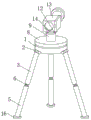
Fig. 1 is a schematic structural view of the present invention;
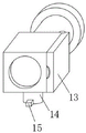
FIG. 2 is a schematic structural view of the machine body of the present invention;
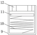
FIG. 3 is a schematic structural view of the connecting sleeve of the present invention;
FIG. 4 is a schematic view of the inner structure of the connecting sleeve of the present invention;
FIG. 5 is a schematic view of the connection structure of the base and the turntable of the present invention;
fig. 6 is a schematic view of a connection structure of the first support rod and the second support rod of the present invention.
In the figure: 1. a base; 2. a hinged seat; 3. a first support bar; 4. concave holes; 5. a second support bar; 6. connecting columns; 7. hinging a shaft; 8. a turntable; 9. a connecting sleeve; 10. a spring; 11. a touch panel; 12. a card slot; 13. a body; 14. connecting the loop bar; 15. a clamping block; 16. and (5) contacting the pins.
Detailed Description
The technical solutions in the embodiments of the present invention will be described clearly and completely with reference to the accompanying drawings in the embodiments of the present invention, and it is obvious that the described embodiments are only some embodiments of the present invention, not all embodiments. Based on the embodiments in the present invention, all other embodiments obtained by a person skilled in the art without creative work belong to the protection scope of the present invention.
Referring to fig. 1-6, a camera convenient for disassembly and assembly comprises a base 1, a hinge base 2 is arranged at the bottom end of the outer side of the base 1, the base 1 is movably connected with a first support rod 3 through the hinge base 2, a concave hole 4 is arranged at the bottom end of the inner side of the first support rod 3, an inner wall of the concave hole 4 is provided with an internal thread, a second support rod 5 is detachably connected with the end thread of the first support rod 3, a connection column 6 matched with the concave hole 4 is arranged at the top end of the second support rod 5, an external thread matched with the internal thread is arranged at the outer side of the connection column 6, a hinge shaft 7 is connected with the top of the base 1, a rotary disc 8 is rotatably connected with the upper part of the base 1 through the hinge shaft 7, a connection sleeve 9 is arranged at the top of the rotary disc 8, a spring 10 is arranged inside the connection sleeve 9, a touch panel 11 is connected at, the inside of the connecting sleeve 9 is movably connected with a connecting sleeve rod 14, the connecting sleeve 9 is connected with the machine body 13 through the connecting sleeve rod 14, and the bottom end of the outer side of the connecting sleeve rod 14 is symmetrically provided with clamping blocks 15 corresponding to the clamping grooves 12.
The utility model discloses a divide into first bracing piece 3 and 5 two parts of second bracing piece with the bracing piece, and first bracing piece 3 can be dismantled with 5 accessible screw threads of second bracing piece and be connected, during the use, is connected first bracing piece 3 and second bracing piece 5, simple to operate, when not using, separates first bracing piece 3 and second bracing piece 5, portable and deposit, and it is convenient to dismantle.
Please refer to fig. 1, the number of the first supporting rods 3 is three groups, and the three groups of the first supporting rods 3 are distributed in a triangle, the utility model discloses a triangle-shaped sets of the first supporting rods 3, which can stabilize the frame structure, thereby making the body 13 keep stable.
Please refer to fig. 1, the outer side of the connecting rod 14 is attached to the inner side of the connecting sleeve 9, so as to prevent the connecting rod 14 from shaking, and thus the body 13 is kept stable.
Please refer to fig. 1, the bottom of the second support rod 5 is provided with the feeler 16, the contact area with the ground can be increased by the antenna 16 arranged at the bottom of the second support rod 5, so as to avoid the second support rod 5 from deviating.
Please refer to fig. 1 and fig. 6, the first support rod 3 and the second support rod 5 are made of aluminum alloy, and the outer diameters of the first support rod 3 and the second support rod 5 are the same, the utility model discloses a will, the material of the first support rod 3 and the second support rod 5 is the aluminum alloy that sets up, is difficult for rusting, and the quality is lighter.
Please refer to fig. 5, the rotation angle of the rotary plate 8 with the hinge shaft 7 as the axis is zero to one hundred eighty degrees, the present invention uses the hinge shaft 7 as the axis to rotate the rotary plate 8, so as to drive the body 13 to move through the rotary plate 8, thereby adjusting the angle of the body.
The working principle is as follows: firstly, assembling a bracket, screwing a connecting column 6 at the top end of a second supporting rod 5 into a concave hole 4 at the bottom end of a first supporting rod 3 under the interaction of threads, completing the connection of the first supporting rod 3 and the second supporting rod 5, opening three groups of first supporting rods 3 through a hinged seat 2, then installing a machine body 13 and the bracket, clamping two groups of clamping blocks 15 at the bottom end of the outer side of a connecting sleeve rod 14 at the bottom of the machine body 13 into clamping grooves 12 on a connecting sleeve 9, pressing downwards, extruding a spring 10 through a touch plate 11, then rotationally connecting the connecting sleeve rod 14 through the machine body 13, enabling the clamping blocks 15 on the connecting sleeve rod 14 to deviate from the clamping grooves 12 on the connecting sleeve 9, resetting the spring 10, extruding the connecting sleeve rod 14 through the touch plate 11, completing the connection of the connecting sleeve rod 14 and the connecting sleeve 9, thus installing the machine body 13 and the bracket, after the machine body 13 is connected with the bracket, if the angle of the machine body 13 needs to be adjusted, use articulated shaft 7 to rotate carousel 8 as the axle, thereby drive organism 13 through carousel 8 and move, with the angle of this adjustment organism, need not to move whole support, when dismantling, press down through organism 13 and connect loop bar 14 and rotate, make the fixture block 15 on the connecting loop bar 14 corresponding with draw-in groove 12 on the connecting sleeve 9, can extract and connect loop bar 14, thereby separate organism 13 and support, then rotate second bracing piece 5, make spliced pole 6 on 5 tops of second bracing piece and the shrinkage pool 4 of 3 bottoms of first bracing piece separate under the interact of screw thread, thereby make first bracing piece 3 separate with second bracing piece 5, and convenient to carry and deposit.
It is obvious to a person skilled in the art that the invention is not restricted to details of the above-described exemplary embodiments, but that it can be implemented in other specific forms without departing from the spirit or essential characteristics of the invention. The present embodiments are therefore to be considered in all respects as illustrative and not restrictive, the scope of the invention being indicated by the appended claims rather than by the foregoing description, and all changes which come within the meaning and range of equivalency of the claims are therefore intended to be embraced therein. Any reference sign in a claim should not be construed as limiting the claim concerned.
Claims (6)
1. A camera convenient to dismantle and install, includes base (1), its characterized in that: the bottom outside the base (1) is provided with a hinged seat (2), the base (1) is movably connected with a first support rod (3) through the hinged seat (2), the bottom inside the first support rod (3) is provided with a concave hole (4), the inner wall of the concave hole (4) is provided with an internal thread, the end thread of the first support rod (3) is detachably connected with a second support rod (5), the top end of the second support rod (5) is provided with a connecting column (6) which is mutually matched with the concave hole (4), the outside of the connecting column (6) is provided with an external thread which is mutually matched with the internal thread, the top of the base (1) is connected with a hinged shaft (7), the upper part of the base (1) is rotatably connected with a rotary table (8) through the hinged shaft (7), the top of the rotary table (8) is provided with a connecting sleeve (9), the inside of the connecting sleeve (9) is, and the top of spring (10) is connected with touch panel (11), the both sides on the inboard top of connecting sleeve (9) all are provided with draw-in groove (12), the inside swing joint of connecting sleeve (9) has connecting loop bar (14), and connecting sleeve (9) are through connecting loop bar (14) connection organism (13), the bottom symmetry in the connecting loop bar (14) outside is provided with fixture block (15) that corresponds each other with draw-in groove (12).
2. A camera for facilitating disassembly and assembly as claimed in claim 1, wherein: the number of the first supporting rods (3) is three, and the three groups of the first supporting rods (3) are distributed in a triangular shape.
3. A camera for facilitating disassembly and assembly as claimed in claim 1, wherein: the outer side of the connecting loop bar (14) is attached to the top end of the inner side of the connecting sleeve (9).
4. A camera for facilitating disassembly and assembly as claimed in claim 1, wherein: the bottom of the second support rod (5) is provided with a contact pin (16).
5. A camera for facilitating disassembly and assembly as claimed in claim 1, wherein: the first supporting rod (3) and the second supporting rod (5) are made of aluminum alloy, and the outer diameters of the first supporting rod (3) and the second supporting rod (5) are consistent.
6. A camera for facilitating disassembly and assembly as claimed in claim 1, wherein: the rotation angle of the turntable (8) taking the hinge shaft (7) as the shaft is zero to one hundred and eighty degrees.
Priority Applications (1)
| Application Number | Priority Date | Filing Date | Title |
|---|---|---|---|
| CN201922385096.9U CN211821527U (en) | 2019-12-26 | 2019-12-26 | Camera convenient to dismantle and install |
Applications Claiming Priority (1)
| Application Number | Priority Date | Filing Date | Title |
|---|---|---|---|
| CN201922385096.9U CN211821527U (en) | 2019-12-26 | 2019-12-26 | Camera convenient to dismantle and install |
Publications (1)
| Publication Number | Publication Date |
|---|---|
| CN211821527U true CN211821527U (en) | 2020-10-30 |
Family
ID=73035878
Family Applications (1)
| Application Number | Title | Priority Date | Filing Date |
|---|---|---|---|
| CN201922385096.9U Active CN211821527U (en) | 2019-12-26 | 2019-12-26 | Camera convenient to dismantle and install |
Country Status (1)
| Country | Link |
|---|---|
| CN (1) | CN211821527U (en) |
Cited By (2)
| Publication number | Priority date | Publication date | Assignee | Title |
|---|---|---|---|---|
| CN113685665A (en) * | 2021-08-13 | 2021-11-23 | 河北道桥工程检测有限公司 | Road engineering surveying instrument |
| CN113758418A (en) * | 2021-09-06 | 2021-12-07 | 北京城建亚泰建设集团有限公司 | Three-dimensional scanning device for positioning ice-making calandria and using method thereof |
-
2019
- 2019-12-26 CN CN201922385096.9U patent/CN211821527U/en active Active
Cited By (2)
| Publication number | Priority date | Publication date | Assignee | Title |
|---|---|---|---|---|
| CN113685665A (en) * | 2021-08-13 | 2021-11-23 | 河北道桥工程检测有限公司 | Road engineering surveying instrument |
| CN113758418A (en) * | 2021-09-06 | 2021-12-07 | 北京城建亚泰建设集团有限公司 | Three-dimensional scanning device for positioning ice-making calandria and using method thereof |
Similar Documents
| Publication | Publication Date | Title |
|---|---|---|
| CN211821527U (en) | Camera convenient to dismantle and install | |
| CN111520602B (en) | Equipment convenient to transform intelligent audio-visual product shooting angle | |
| CN111473228A (en) | Display screen for computer of convenient equipment | |
| CN214171811U (en) | LED support of outdoor display screen | |
| CN208804410U (en) | A kind of broadcast stereo production erection bracket | |
| CN211015000U (en) | Multifunctional projection screen support | |
| CN109611662B (en) | Multi-degree-of-freedom assembly structure for L ED display screen | |
| CN211176019U (en) | Multipurpose base for paperless conference display screen | |
| CN209801059U (en) | Multimedia teaching device for hotel management | |
| CN210291230U (en) | Arc surface display equipment based on large screen display system | |
| CN216768957U (en) | Multifunctional photographic support | |
| CN210319204U (en) | Rotatable liquid crystal television | |
| CN215770421U (en) | Teaching show board convenient to detach and install for intellectual property training | |
| CN211232159U (en) | Special support for film and television display | |
| CN111064913B (en) | Automatic rotatory flexible audio amplifier and flat-panel television | |
| CN219389127U (en) | Support convenient to equipment | |
| CN215646972U (en) | Detachable prompter ware that broadcaster used | |
| CN214663436U (en) | Super-clear full-color non-blue-light curved-surface liquid crystal display | |
| CN214839975U (en) | Projection equipment for digital media | |
| CN219606524U (en) | Liquid crystal display capable of being adjusted at multiple angles | |
| CN213299294U (en) | Display fixing device for support frame | |
| CN219678531U (en) | Two-fold type camera support protective housing | |
| CN215764495U (en) | From angle self-interacting projection arrangement for media teaching based on thing networking | |
| CN220191002U (en) | Special fixed bolster of film and television recording | |
| CN215635947U (en) | Display screen for playing movie and television animation |
Legal Events
| Date | Code | Title | Description |
|---|---|---|---|
| GR01 | Patent grant | ||
| GR01 | Patent grant | ||
| TR01 | Transfer of patent right | ||
| TR01 | Transfer of patent right |
Effective date of registration: 20220615 Address after: 332000 Room 201, Houde building, Jiujiang University Science Park, Lianxi District, Jiujiang City, Jiangxi Province Patentee after: Jiangxi Feifan Digital Technology Co.,Ltd. Address before: 233500 Li Cang Zhen Bao Tai Gou Cun Heng Zhuang 2, Mengcheng County, Bozhou City, Anhui Province Patentee before: Wang Guoyuan |