CN211813725U - Waste water treatment device - Google Patents
Waste water treatment device Download PDFInfo
- Publication number
- CN211813725U CN211813725U CN201922091045.5U CN201922091045U CN211813725U CN 211813725 U CN211813725 U CN 211813725U CN 201922091045 U CN201922091045 U CN 201922091045U CN 211813725 U CN211813725 U CN 211813725U
- Authority
- CN
- China
- Prior art keywords
- sludge
- tank
- connecting block
- purification tank
- water
- Prior art date
- Legal status (The legal status is an assumption and is not a legal conclusion. Google has not performed a legal analysis and makes no representation as to the accuracy of the status listed.)
- Active
Links
Images


Landscapes
- Filtration Of Liquid (AREA)
Abstract
The utility model discloses a wastewater treatment device, which belongs to the technical field of sewage treatment. The wastewater treatment device comprises a purification tank, a sludge recovery tank, a dehydration mechanism, a wastewater clean water tank, a primary filtering mechanism and a filtering bin. One side of the top of the purification tank is provided with a water inlet pipe, the other side of the purification tank is provided with an overflow pipe communicated with one end of the primary filtering mechanism, the other end of the primary filtering mechanism is communicated with the filtering bin, and the bottom of the filtering bin is provided with a water outlet; the purification tank is internally provided with at least one purification tank, a sedimentation plate is arranged in the purification tank, the bottom of the purification tank is provided with sludge hoppers, and outlets at the bottom of each sludge hopper are communicated through a communicating pipe; one end of the communicating pipe is connected with a return pipe leading to the purifying tank; the second end of the communicating pipe is communicated with the dewatering mechanism and the waste water clean water tank, and the top of the waste water clean water tank is communicated with the primary filtering mechanism; the top of the sludge recovery tank is communicated with the communicating pipe. The wastewater treatment device can be used for cleaning the sludge deposited on the settling plate and the filter screen more easily, and the blockage phenomenon is avoided.
Description
Technical Field
The invention belongs to the technical field of sewage treatment, and particularly relates to a wastewater treatment device.
Background
The wastewater treatment is to treat the wastewater by physical, chemical and biological methods, purify the wastewater and reduce pollution so as to achieve the purposes of wastewater recovery and reuse and fully utilize water resources. The domestic sewage is the wastewater discharged by people in daily life activities, the wastewater is mainly polluted by domestic waste, and the quantity, components and concentration of pollutants are related to the living habits and water consumption of people. Domestic sewage generally does not contain toxic substances, but it has conditions suitable for the propagation of microorganisms, contains a large amount of bacteria and pathogens, and has a certain hazard from a hygienic viewpoint.
Under the background of rapid development of social economy, environmental pollution becomes a problem which needs to be dealt with and solved, and the problem is closely linked with the national economic development level and increasingly highlighted. Due to the technical lag, capital shortage and great treatment difficulty, the urban environment and construction thereof are always affected by the problem of wastewater treatment. If these problems are not solved as soon as possible, environmental pollution will be more serious as water consumption is continuously increased along with the advance of urbanization.
Current effluent treatment plant has some weak points, and effluent treatment generally has the step of sediment filteration, generally has a large amount of mud on the sediment board, does not clear up for a long time, just has the condition that is difficult to handle to appear, secondly, at filterable in-process, the filter screen generally sets up in filtering the storehouse, all is that waste water filters and just can clear up it after accomplishing, therefore the phenomenon of jam appears easily in the filter screen.
Disclosure of Invention
In view of the above-mentioned drawbacks and deficiencies of the prior art, it would be desirable to provide a wastewater treatment device that solves the problems set forth in the background above.
The utility model provides a technical scheme that above-mentioned problem adopted: the device comprises a purification tank, a sludge treatment module, a wastewater clean water tank, a primary filtering mechanism and a filtering bin, wherein a water inlet pipe is arranged on one side of the top of the purification tank, an overflow pipe communicated with a first end of the primary filtering mechanism is arranged on the other side of the top of the purification tank, a second end of the primary filtering mechanism is communicated with the filtering bin, and a water outlet is arranged at the bottom of the filtering bin; the device comprises a purification tank, a pump A, a return pipe, a sludge hopper, a sludge storage tank, a sludge discharge tank, a pump B and a return pipe, wherein at least one purification tank is arranged in the purification tank, a sedimentation plate is arranged in the purification tank, the bottom of the purification tank is provided with the sludge hopper, the outlet at the bottom of the sludge hopper is connected; the second end of the communicating pipe is communicated with the wastewater clean water tank, and the top of the wastewater clean water tank is communicated with the first end of the primary filtering mechanism.
Further, the sludge treatment module includes sludge recycling tank and dewatering mechanism, sludge recycling tank pass through the tee junction head with the export communicating pipe of sludge bucket meets, the tee junction head with be equipped with control valve c between sludge recycling tank, dewatering mechanism first end pass through control valve B with the sludge bucket export is linked together, dewatering mechanism's second end pass through pump B with the clear water basin bottom is linked together, dewatering mechanism bottom is equipped with out the mud mouth.
Further, purify the quantity of groove, precipitate board and sludge hopper and be three, three purify the groove and set up side by side, and adjacent two purify top intercommunication between the groove, three sludge hopper bottom export is linked together through communicating pipe.
Furthermore, the surface of the sedimentation plate is provided with a plurality of pipelines which are arranged in parallel and have openings at two ends, a plurality of water spraying ports are formed in the pipelines, and a water inlet is formed in one side of the sedimentation plate and is communicated with the water pump through the pipeline.
Further, elementary filtering mechanism contains connecting block, well connecting block and lower connecting block, go up connecting block, well connecting block and lower connecting block both sides and be equipped with connecting portion respectively, will through bolt and nut connecting portion link to each other respectively to with last connecting block and well connecting block, well connecting block and lower connecting block fixed connection respectively. The top of going up the connecting block has seted up the feed inlet, the discharge gate has been seted up to the bottom of lower connecting block, the feed inlet with be equipped with one-level filter screen and second grade filter screen between the discharge gate.
Further, the diameter of the sludge hopper close to one end of the settling plate is larger than that of the other end of the settling plate, a control valve a is arranged between the first end of a sludge hopper communicating pipe and the pump A, and a control valve b is arranged between the second end of the sludge hopper communicating pipe and the dewatering mechanism.
Furthermore, a pump B is arranged between the top of the dewatering mechanism and the wastewater clean water tank, and a pump C and a control valve d are arranged between the top of the wastewater clean water tank and the primary filtering mechanism.
Furthermore, a control valve e is arranged between the overflow pipe at the other side of the top of the purification tank and the primary filtering mechanism.
The utility model discloses beneficial effect who has: waste water treatment device, on the one hand, through purifying the groove at the inside setting of purification tank, set up the precipitate board in purifying the groove, set up the water jet on precipitate board pipeline, through spouting water from the water jet, can be used to oxygenation in the purification tank, can also prevent simultaneously that mud from piling up difficult clearance on the pipeline of precipitate board, on the other hand, the top of crossing the filter house is provided with primary filter mechanism, be equipped with convenient to detach's one-level filter screen and second grade filter screen in the primary filter mechanism, wash the filter screen more easily, can prevent effectively that the filth from causing the jam. In addition, be equipped with sewage backward flow and sludge dewatering mechanism, can effectively carry out rapid draing to the precipitate, prevent to block up.
Drawings
Other features, objects and advantages of the present application will become more apparent upon reading of the following detailed description of non-limiting embodiments thereof, made with reference to the accompanying drawings in which:
FIG. 1 is an overall view of a preferred embodiment of a wastewater treatment apparatus according to the present invention;
FIG. 2 is a schematic diagram of a settling plate structure of the wastewater treatment device of the present invention;
FIG. 3 is a schematic structural view of a primary filtering mechanism of the wastewater treatment device of the present invention;
FIG. 4 is an overall view of another embodiment of the wastewater treatment apparatus of the present invention.
In the figure: 1. a purification tank; 2. a purification tank; 3. a return pipe; 4. a water inlet pipe; 5. a settling plate; 501. a water inlet; 502. a water jet; 503. a pipeline; 6. a water pump; 7. a sludge hopper; 8. A pump A; 801. a pump B; 802. a pump C; 9. a control valve a; 901. a control valve b; 902. control valves c, 903, and control valve d; 904. a control valve e; 10. a three-way connector; 11. a sludge recovery tank; 12. a dewatering mechanism; 13. a sludge outlet; 14. a wastewater clean water tank; 15. a primary filtration mechanism; 1501. a feed inlet; 1502. a first-stage filter screen; 1503. an upper connecting block; 1504. a middle connecting block; 1505. a lower connecting block; 1506. a secondary filter screen; 1507. a discharge port; 16. a filtering bin; 17. and (7) a water outlet.
Detailed Description
The present invention will be described in further detail with reference to the accompanying drawings and examples. It is to be understood that the specific embodiments described herein are merely illustrative of the relevant invention and not restrictive of the invention. All other embodiments, which can be derived by a person skilled in the art from the embodiments given herein without making any creative effort, shall fall within the protection scope of the present invention. It should be noted that, for convenience of description, only the portions related to the present invention are shown in the drawings.
Example one
As shown in FIG. 1, a wastewater treatment apparatus comprises a purification tank 1, a sludge recovery tank 11, a dewatering mechanism 12, a wastewater clean water tank 14, a primary filtering mechanism 15 and a filtering bin 16. 1 top one side of purification tank is equipped with inlet tube 4, and inlet tube 4 is arranged in letting in the waste water of pending purification tank 1, and 1 top opposite side of purification tank is equipped with the overflow pipe that is linked together with the first end of primary filter device 15, is equipped with control valve (e)904 on the overflow pipe, and the overflow pipe is used for will filtering through purification tank sedimentation treatment back upper clear water inflow primary filter device. The second end of the primary filtering mechanism 15 is communicated with a filtering bin 16, and the bottom of the filtering bin 16 is provided with a water outlet. The three purification tanks 2 are arranged in the purification tank 1, the lower parts of the three purification tanks 2 are separated, the tops of the three purification tanks 2 are communicated, the interior of each purification tank 2 is respectively provided with a sedimentation plate 5, the bottom of each purification tank 2 is respectively provided with a sludge hopper 7, the diameter of one end, close to the sedimentation plate 5, of each sludge hopper 7 is larger than that of one end, far away from the sedimentation plate 5, of each sludge hopper 7, the bottom outlets of the sludge hoppers 7 are mutually communicated through a communicating pipe, the left end of each communicating pipe is connected with a control valve (a)9, a pump (A)8 and a return pipe 3, the outlets of the return pipes 3 are arranged at the tops of the purification tanks 2, and sludge after sedimentation treatment, passing through the sludge hoppers 7 can enter the purification tanks; the right end of a communicating pipe of the sludge hopper 7 is communicated with a dehydration mechanism 12 and the wastewater clean water tank 14 through a control valve (B)901, the bottom of the dehydration mechanism 12 is provided with a sludge outlet 13, the top of the dehydration mechanism 12 is communicated with the bottom of the wastewater clean water tank 14 through a pump (B)801, and the top of the wastewater clean water tank 14 is communicated with an overflow pipe at the first end of a primary filtering mechanism 15 through a pump (C)802 and a control valve (d) 903; the middle of the communicating pipe of the sludge hopper 7 is provided with a three-way connector 10, and the middle connector of the three-way connector 10 is communicated with a sludge recovery tank 11 through a control valve (c).
The dewatering mechanism 12 is a centrifugal deslimer, impurities and particles in the sludge are separated by centrifugal force generated by high-speed rotation and are thrown out from the sludge outlet 13, and the separated water enters the wastewater clean water tank 14 through a pipeline under the action of the pump (B) 801.
The control valve (a)9, the control valve (b)901, the control valve (c)902, the control valve (d)903 and the control valve (e)904 are all made of corrosion-resistant stainless steel butterfly valves and are used for controlling the flow direction of slurry or clean water, wherein the control valve (a)9 is used for controlling the backflow of sludge, the control valve (b)901 is used for controlling the flow direction of sludge from the sludge hopper 7 to the dehydration mechanism 12, the control valve (c)902 is used for controlling the sludge in the sludge hopper 7 to flow to the sludge recovery tank 11 for recovery, the control valve (d)903 is used for controlling the wastewater in the wastewater clean water tank 14 to flow to the primary filtering mechanism 15 for filtering, and the control valve (e)904 is used for controlling the wastewater purified by the purification tank 1 to overflow to the primary filtering mechanism 15.
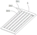
As shown in fig. 2, the settling plate 5 is provided with a plurality of parallel pipes 503 with two open ends, each pipe 503 is provided with a plurality of water spraying openings 502, one side of the top of the settling plate 5 is provided with a water inlet 501, and the water inlet 501 penetrates through the purifying tank 2 through the pipe and is connected with the water pump 6. The water spray opening 502 can spray water into the purifying tank 2, so as to further enrich oxygen in the wastewater and play a role in cleaning the precipitation plate 5.
As shown in fig. 3, the primary filtering mechanism 15 includes an upper connecting block 1503, a middle connecting block 1504, a lower connecting block 1505, the upper connecting block 1503 and the middle connecting block 1504, the middle connecting block 1504 and the lower connecting block 1505 are fixedly connected with each other through bolts and nuts, a feed inlet 1501 is formed in the top of the upper connecting block 1503, a discharge outlet 1507 is formed in the bottom of the lower connecting block 1505, a primary filter screen 1502 and a secondary filter screen 1506 are arranged in the primary filtering mechanism 15, clean water overflowing through an overflow pipe on one side of the purifying tank 1 and clean water pumped out through the wastewater clean water tank 14 flow into the primary filtering mechanism 15 from the feed inlet 1501, and after being filtered twice through the primary filter screen 1502 and the secondary filter screen 1506, the clean water flows into. The primary filter screen and the secondary filter screen are both circular corrosion-resistant stainless steel filter screens, wherein the primary filter screen is a 100-mesh filter screen, the secondary filter screen is a 200-mesh filter screen, and the secondary filter screen is a 200-mesh filter screen, so that impurities which are not precipitated in sewage can be filtered preliminarily by adopting the two-stage filter screens.
The filtering bin 16 is made of carbon steel Q235 material, the inner part of the filtering bin is coated with lining glue for corrosion prevention, the filtering material such as quartz sand or anthracite is filled in the filtering bin, sheet-shaped objects aggregated by suspended matters in water or bonded colloidal particles which cannot be removed by methods such as precipitation and the like can be filtered again, and clear water flows out from a water outlet 17 at the bottom of the filtering bin 16 and can be used for irrigation water for life, industry or agriculture.
In this embodiment, the working principle of the wastewater treatment device is as follows: domestic waste water pours into purification tank 1 inside through inlet tube 4, purify the precipitation treatment through purification tank 2 in the purification tank 1, after through deposiing in purification tank 2, the clear water enters into next purification tank 2 through the top of purification tank 2 in, carry out the secondary and purify the precipitation treatment, then enter into next purification tank 2 and carry out the purification precipitation treatment of the third time, the clear water after tertiary purification precipitation flows into primary filter mechanism 15 through the overflow pipe of purification tank 1 one side, and after carrying out the two-stage filtration through primary filter mechanism 15, flow into in filtering storehouse 16 at last, flow out through delivery port 17. The mud that purifies the sediment can get into sludge bucket 7, pile up the mud in sludge bucket 7, on the one hand, through pump A effect through the back flow reentrant purification tank 1 and purify the sediment processing, on the one hand, can directly get into sludge recycling groove 11 through three way connection head 10, on the other hand, mud also can flow into dewatering mechanism 12 and carry out dehydration, the mud of taking off partial moisture is discharged through mud mouth 13, the muddy water that is taken off gets into waste water clear water pond through pump B and handles, then get into elementary filter mechanism 15 through pump C and control valve d, and after carrying out the two-stage filtration through elementary filter mechanism 15, flow into in filtering bunker 16 at last, flow out through delivery port 17. The sludge treatment modes in the three sludge hoppers 7 can be used simultaneously, and can also be selectively used according to the requirements of users, the flow direction of the sludge in the sludge hoppers 7 is controlled by each control valve, and one or more treatment modes can be selected to be matched for use.
Example two
As shown in FIG. 4, a wastewater treatment apparatus comprises a purification tank 1, a sludge recovery tank 11, a dewatering mechanism 12, a wastewater clean water tank 14, a primary filtration mechanism 15 and a filtration bin 16. 1 top one side of purification tank is equipped with inlet tube 4, and inlet tube 4 is arranged in letting in the waste water of pending purification tank 1, and 1 top opposite side of purification tank is equipped with the overflow pipe that is linked together with the first end of primary filter device 15, is equipped with control valve (e)904 on the overflow pipe, and the overflow pipe is used for will filtering through purification tank sedimentation treatment back upper clear water inflow primary filter device. The second end of the primary filtering mechanism 15 is communicated with a filtering bin 16, and the bottom of the filtering bin 16 is provided with a water outlet. A purification tank 2 is arranged in the purification tank 1, a precipitation plate 5 is arranged in the purification tank 2, a sludge hopper 7 is arranged at the bottom of the purification tank 2, the diameter of one end, close to the precipitation plate 5, of the sludge hopper 7 is larger than that of the end, far away from the precipitation plate 5, of the sludge hopper 7, the left end of the outlet at the bottom of the sludge hopper 7 is connected with a control valve (a)9, a pump (A)8 and a return pipe 3 through communicating pipes, the outlet of the return pipe 3 is arranged at the top of the purification tank 2, and sludge passing through the sludge hopper 7 after the precipitation treatment can enter the purification tank again through the return pipe under the action of the control valve (a)9 and; the right end of an outlet communicating pipe of the sludge bucket 7 is communicated with a dehydration mechanism 12 and the waste water clean water tank 14 through a control valve (B)901, the bottom of the dehydration mechanism 12 is provided with a sludge outlet 13, the top of the dehydration mechanism 12 is communicated with the bottom of the waste water clean water tank 14 through a pump (B)801, and the top of the waste water clean water tank 14 is communicated with an overflow pipe at the first end of the primary filtering mechanism 15 through a pump (C)802 and a control valve (d) 903; the middle of the communicating pipe of the sludge hopper 7 is provided with a three-way connector 10, and the middle connector of the three-way connector 10 is communicated with a sludge recovery tank 11 through a control valve (c).
The dewatering mechanism 12 is a centrifugal deslimer, impurities and particles in the sludge are separated by centrifugal force generated by high-speed rotation and are thrown out from the sludge outlet 13, and the separated water enters the wastewater clean water tank 14 through a pipeline under the action of the pump (B) 801.
The control valve (a)9, the control valve (b)901, the control valve (c)902, the control valve (d)903 and the control valve (e)904 adopt corrosion-resistant stainless steel butterfly valves and are used for controlling the flow direction of wastewater, wherein the control valve (a)9 is used for controlling the backflow of sludge, the control valve (b)901 is used for controlling the flow direction of sludge from the sludge hopper 7 to the dehydration mechanism 12, the control valve (c)902 is used for controlling the sludge in the sludge hopper 7 to flow to the sludge recovery tank 11 for recovery, the control valve (d)903 is used for controlling the wastewater in the wastewater clean water tank 14 to flow to the primary filtering mechanism 15 for filtering, and the control valve (e)904 is used for controlling the wastewater purified by the purification tank 1 to overflow to the primary filtering mechanism 15.
As shown in fig. 2, the settling plate 5 is provided with a plurality of parallel pipes 503 with two open ends, each pipe 503 is provided with a plurality of water spraying openings 502, one side of the top of the settling plate 5 is provided with a water inlet 501, and the water inlet 501 penetrates through the purifying tank 2 through the pipe and is connected with the water pump 6. The water spray opening 502 can spray water into the purifying tank 2, so as to further enrich oxygen in the wastewater and play a role in cleaning the precipitation plate 5.
As shown in fig. 3, the primary filtering mechanism 15 includes an upper connecting block 1503, a middle connecting block 1504, a lower connecting block 1505, the upper connecting block 1503 and the middle connecting block 1504, the middle connecting block 1504 and the lower connecting block 1505 are fixedly connected with each other through bolts and nuts, a feed inlet 1501 is formed in the top of the upper connecting block 1503, a discharge outlet 1507 is formed in the bottom of the lower connecting block 1505, a primary filter screen 1502 and a secondary filter screen 1506 are arranged in the primary filtering mechanism 15, clean water overflowing through an overflow pipe on one side of the purifying tank 1 and clean water pumped out through the wastewater clean water tank 14 flow into the primary filtering mechanism 15 from the feed inlet 1501, and after being filtered twice through the primary filter screen 1502 and the secondary filter screen 1506, the clean water flows into. The primary filter screen and the secondary filter screen are both circular corrosion-resistant stainless steel filter screens, wherein the primary filter screen is a 100-mesh filter screen, the secondary filter screen is a 200-mesh filter screen, and the secondary filter screen is a 200-mesh filter screen, so that impurities which are not precipitated in sewage can be filtered preliminarily by adopting the two-stage filter screens.
The filtering bin 16 is made of carbon steel Q235 material, the inner part of the filtering bin is coated with lining glue for corrosion prevention, the filtering material such as quartz sand or anthracite is filled in the filtering bin, sheet-shaped objects aggregated by suspended matters in water or bonded colloidal particles which cannot be removed by methods such as precipitation and the like can be filtered again, and clear water flows out from a water outlet 17 at the bottom of the filtering bin 16 and can be used for irrigation water for life, industry or agriculture.
The working principle of the wastewater treatment device in the second embodiment is as follows: domestic waste water pours into inside the purification tank 1 through inlet tube 4, purifies through the purification tank 2 in the purification tank 1 and deposits the processing, after through deposiing in the purification tank 2, the clear water flows into primary filter mechanism 15 through the overflow pipe of purification tank 1 one side to after carrying out the two-stage filtration through primary filter mechanism 15, flow into in filtering storehouse 16 at last, flow out through delivery port 17. The sludge after purification and precipitation can enter the sludge hopper 7, the sludge accumulated in the sludge hopper 7 can enter the purification tank 1 again for purification and precipitation treatment through the action of the pump A through the return pipe, on the one hand, the sludge can directly enter the sludge recovery tank 11 through the three-way connector 10, on the other hand, the sludge can also flow into the dehydration mechanism 12 for dehydration treatment, the sludge with part of moisture removed is discharged through the sludge outlet 13, the removed muddy water enters the wastewater clear water tank for treatment through the pump B, then enters the primary filtering mechanism 15 through the pump C and the control valve d, and finally flows into the filtering bin 16 after the primary filtering mechanism 15 is subjected to two-stage filtration, and flows out through the water outlet 17. The sludge treatment modes in the three sludge hoppers 7 can be used simultaneously, and can also be selectively used according to the requirements of users, the flow direction of the sludge in the sludge hoppers 7 is controlled by each control valve, and one or more treatment modes can be selected to be matched for use.
It should be understood that in the description of the present invention, the terms "left", "right", "top", "bottom", "one side", "second side", "first end", "second end", "inner", "upper", etc. used herein indicate the orientation or positional relationship based on the drawings, and are only for convenience of description and simplicity of description, and do not indicate that the position or element referred to must have a specific orientation, a specific configuration, and thus, should not be construed as limiting the present invention.
The above embodiments are merely illustrative of the present invention and not restrictive, and although detailed descriptions may be made with reference to the embodiments, those skilled in the art will understand that: the technical solutions described in the foregoing embodiments may still be modified, or some or all of the technical features may be equivalently replaced; such modifications and substitutions do not depart from the spirit and scope of the embodiments of the present invention.
Claims (10)
1. A wastewater treatment device is characterized in that: the device comprises a purification tank (1), a sludge treatment module, a wastewater clean water tank (14), a primary filtering mechanism (15) and a filtering bin (16), wherein a water inlet pipe (4) is arranged on one side of the top of the purification tank (1), an overflow pipe communicated with a first end of the primary filtering mechanism (15) is arranged on the other side of the top of the purification tank (1), a second end of the primary filtering mechanism (15) is communicated with the filtering bin (16), and a water outlet (17) is formed in the bottom of the filtering bin (16); at least one purification tank (2) is arranged in the purification tank (1), a precipitation plate (5) is arranged inside the purification tank (2), a sludge hopper (7) is arranged at the bottom of the purification tank (2), the bottom outlet of the sludge hopper (7) is connected with a pump A (8) and a return pipe (3) through the first end of a communicating pipe, and the outlet of the return pipe (3) is arranged in the purification tank (2); the second end of the communicating pipe is communicated with the bottom of the waste water clean water tank (14), and the top of the waste water clean water tank (14) is communicated with the first end of the primary filtering mechanism (15).
2. The wastewater treatment apparatus according to claim 1, characterized in that: the sludge treatment module includes sludge recuperation groove (11) and dehydration mechanism (12), sludge recuperation groove (11) through tee junction head (10) with sludge bucket (7) export communicating pipe meets mutually, tee junction head (10) with be equipped with control valve c (902) between sludge recuperation groove (11), dehydration mechanism (12) first end through control valve B (901) with sludge bucket (7) export is linked together, the second end of dehydration mechanism (12) through pump B (801) with waste water clean water basin (14) are linked together, dehydration mechanism (12) bottom is equipped with mud outlet (13).
3. The wastewater treatment apparatus according to claim 1, characterized in that: purify the quantity of groove (2), precipitate board (5) and sludge bucket (7) and be three, three purify groove (2) and set up side by side, top intercommunication between two adjacent purification grooves (2), three sludge bucket (7) bottom export is linked together through communicating pipe.
4. The wastewater treatment apparatus according to claim 1, characterized in that: the water pump is characterized in that a plurality of pipelines (503) which are arranged in parallel and are provided with openings at two ends are arranged on the surface of the settling plate (5), a plurality of water spraying ports (502) are formed in the surface of each pipeline (503), a water inlet (501) is formed in one side of the settling plate (5), and the water inlet (501) is communicated with the water pump (6) through a pipeline.
5. The wastewater treatment apparatus according to claim 1, characterized in that: the primary filtering mechanism (15) comprises an upper connecting block (1503), a middle connecting block (1504) and a lower connecting block (1505), wherein connecting parts are respectively arranged on two sides of the upper connecting block (1503), the middle connecting block (1504) and the lower connecting block (1505), and the connecting parts are respectively connected through bolts and nuts, so that the upper connecting block (1503) and the middle connecting block (1504), the middle connecting block (1504) and the lower connecting block (1505) are respectively fixedly connected.
6. The wastewater treatment apparatus according to claim 5, wherein: feed inlet (1501) have been seted up at the top of going up connecting block (1503), discharge gate (1507) have been seted up to the bottom of lower connecting block (1505), feed inlet (1501) with be equipped with one-level filter screen (1502) and second grade filter screen (1506) between discharge gate (1507).
7. The wastewater treatment apparatus according to claim 1, characterized in that: a control valve a (9) is arranged between the outlet of the sludge hopper (7) and the pump A (8).
8. The wastewater treatment apparatus according to claim 1, characterized in that: and a pump C (802) and a control valve d (903) are arranged between the wastewater clean water tank (14) and the primary filtering mechanism (15).
9. The wastewater treatment apparatus according to claim 1, characterized in that: a control valve e (904) is arranged between an overflow pipe arranged at the other side of the top of the purification tank (1) and the primary filtering mechanism (15).
10. The wastewater treatment apparatus according to claim 1, characterized in that: the diameter of one end of the sludge hopper (7) close to the settling plate (5) is larger than that of one end far away from the settling plate (5).
Priority Applications (1)
| Application Number | Priority Date | Filing Date | Title |
|---|---|---|---|
| CN201922091045.5U CN211813725U (en) | 2019-11-28 | 2019-11-28 | Waste water treatment device |
Applications Claiming Priority (1)
| Application Number | Priority Date | Filing Date | Title |
|---|---|---|---|
| CN201922091045.5U CN211813725U (en) | 2019-11-28 | 2019-11-28 | Waste water treatment device |
Publications (1)
| Publication Number | Publication Date |
|---|---|
| CN211813725U true CN211813725U (en) | 2020-10-30 |
Family
ID=73031648
Family Applications (1)
| Application Number | Title | Priority Date | Filing Date |
|---|---|---|---|
| CN201922091045.5U Active CN211813725U (en) | 2019-11-28 | 2019-11-28 | Waste water treatment device |
Country Status (1)
| Country | Link |
|---|---|
| CN (1) | CN211813725U (en) |
Cited By (1)
| Publication number | Priority date | Publication date | Assignee | Title |
|---|---|---|---|---|
| CN113279183A (en) * | 2021-06-25 | 2021-08-20 | 浙江诺亿毛纺印染有限公司 | Wastewater treatment device used in dyeing and finishing process |
-
2019
- 2019-11-28 CN CN201922091045.5U patent/CN211813725U/en active Active
Cited By (1)
| Publication number | Priority date | Publication date | Assignee | Title |
|---|---|---|---|---|
| CN113279183A (en) * | 2021-06-25 | 2021-08-20 | 浙江诺亿毛纺印染有限公司 | Wastewater treatment device used in dyeing and finishing process |
Similar Documents
| Publication | Publication Date | Title |
|---|---|---|
| CN202762212U (en) | Rainwater filter purifier | |
| CN207175619U (en) | A kind of Water purification filter | |
| CN102145953A (en) | Combined sewage treatment system | |
| CN211813725U (en) | Waste water treatment device | |
| CN205258174U (en) | Ultrafiltration sewage treatment system | |
| CN105110507B (en) | Drainage processing equipment is floated in a kind of self-cleaning | |
| CN204779170U (en) | Remove look water purification unit | |
| CN207361975U (en) | A kind of sanitary sewage multi-stage treatment units | |
| CN206342985U (en) | Novel sewage treatment unit | |
| CN209352699U (en) | A kind of high strong brine high-efficient treatment device of trade effluent | |
| CN208802966U (en) | A kind of waterworks water purification installation | |
| CN203346197U (en) | Integrated water purification device | |
| CN205990294U (en) | A kind of plastic processing Waste Water Treatment | |
| CN108947144A (en) | A kind of trade effluent cooperates with processing technological flow and coprocessing system with exhaust gas | |
| CN201694908U (en) | Combined sewage disposal system | |
| CN212982717U (en) | UASB sludge cyclone separator and matched UASB sludge treatment system thereof | |
| CN210710975U (en) | Sloping plate-air flotation mud-water separation tank | |
| CN210176661U (en) | Drinking water purifier | |
| CN207980659U (en) | A kind of effluent treatment plant | |
| CN208022834U (en) | Gravity installation intelligent control backwashing sewage water processing system | |
| CN209276308U (en) | A kind of trade effluent and exhaust gas coprocessing system | |
| CN205907144U (en) | Industrial sewage treatment system | |
| CN207775974U (en) | A kind of rainwater and domestic water recycle device | |
| CN202715311U (en) | Integrated water purifier | |
| CN207243681U (en) | Urban area property wisdom water circulation system |
Legal Events
| Date | Code | Title | Description |
|---|---|---|---|
| GR01 | Patent grant | ||
| GR01 | Patent grant |