CN211808911U - Rear torsion beam assembly of hydraulic bushing - Google Patents
Rear torsion beam assembly of hydraulic bushing Download PDFInfo
- Publication number
- CN211808911U CN211808911U CN201922190457.4U CN201922190457U CN211808911U CN 211808911 U CN211808911 U CN 211808911U CN 201922190457 U CN201922190457 U CN 201922190457U CN 211808911 U CN211808911 U CN 211808911U
- Authority
- CN
- China
- Prior art keywords
- torsion beam
- bushing
- assembly
- hydraulic
- beam assembly
- Prior art date
- Legal status (The legal status is an assumption and is not a legal conclusion. Google has not performed a legal analysis and makes no representation as to the accuracy of the status listed.)
- Active
Links
Images


Landscapes
- Vehicle Body Suspensions (AREA)
- Combined Devices Of Dampers And Springs (AREA)
Abstract
The utility model relates to a torsion beam assembly behind hydraulic pressure bush belongs to the technical field of automobile design and manufacturing. The utility model discloses a hydraulic bushing rear torsion beam assembly, which comprises a torsion beam welding assembly and a hydraulic bushing assembly arranged on the torsion beam welding assembly; the hydraulic bushing assembly comprises an outer sleeve, a rubber bushing body, an inner framework and an inner sleeve. The hydraulic bushing rear torsion beam assembly of the utility model introduces the hydraulic bushing into the torsion beam rear suspension, and the hydraulic bushing rear torsion beam assembly of the utility model introduces the hydraulic bushing into the torsion beam rear suspension, so that the longitudinal impact of the rear axle on the vehicle body can be effectively reduced; and the torsion beam assembly can provide high damping characteristic in a larger frequency range, and the riding comfort of the whole vehicle is improved.
Description
Technical Field
The utility model relates to a technical field of automobile design and manufacturing, more specifically say, the utility model relates to a torsion beam assembly behind hydraulic pressure bush.
Background
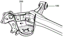
As shown in fig. 1-2, in the prior art, the bushing at the front end of the torsion beam is a common rubber bushing, and is solid or is a hole dug in a certain direction, and the hole dug can reduce the rigidity of the bushing in the corresponding direction and reduce the impact of the rear axle on the vehicle body due to the uneven ground. But the damping force is also reduced as the stiffness is reduced after the bushing is dug. In addition, various hydraulic bushings have been developed in the prior art, which generally include two liquid chambers disposed in the bushing and communicating with each other through a passage, and consume energy by friction generated at an interface or inside the liquid through flow of the liquid, thereby performing a vibration damping function. The conventional hydraulic bushing in the prior art has high dynamic and static rigidity, and cannot effectively reduce the longitudinal impact of a rear shaft on a vehicle body.
SUMMERY OF THE UTILITY MODEL
For the above-mentioned technical problem who exists among the solution prior art, the utility model aims at providing a torsion beam assembly behind hydraulic pressure bush.
The utility model discloses a hydraulic bushing rear torsion beam assembly, which comprises a torsion beam welding assembly and a hydraulic bushing assembly arranged on the torsion beam welding assembly; the hydraulic bushing assembly comprises an outer sleeve, a rubber bushing body, an inner framework and an inner sleeve; the rubber bushing body is fixed between the inner sleeve and the outer sleeve, and the inner framework is fixed inside the rubber bushing body; the rubber bushing body comprises a cylindrical base body, the inner framework comprises an annular body, and a plurality of throttling holes are formed in the side wall of the annular body along the circumferential direction; a first liquid chamber and a second liquid chamber are arranged inside the rubber bushing body, are symmetrically arranged along the axial direction of the rubber bushing body and are independent from each other, and oil liquid is filled in the first liquid chamber and the second liquid chamber; an annular channel is also arranged in the rubber bushing body and is arranged in the rubber bushing body between the inner framework and the outer sleeve; the first liquid chamber and the second liquid chamber are provided with a plurality of through holes which are in one-to-one correspondence with the throttling holes and are communicated with the annular channel; the inner wall of the rubber bushing body is provided with a limiting bulge, and the middle part of the inner sleeve is provided with an expansion surface corresponding to the limiting bulge.
The first liquid chamber comprises two liquid separating chambers, the two liquid separating chambers are arranged along the axis direction of the rubber bushing body, the two liquid separating chambers are connected through a communication channel, and the through hole is communicated with the communication channel.
The second liquid chamber comprises two liquid separating chambers, the two liquid separating chambers are arranged along the axis direction of the rubber bushing body, the two liquid separating chambers are connected through a communication channel, and the through hole is communicated with the communication channel.
Wherein the length direction of the communication channel is perpendicular to the length direction of the through hole; and the expansion surface of the inner sleeve is arranged adjacent to the communication channel and is positioned between the two liquid separation chambers.
The rubber bushing body further comprises a front cone arranged at the front end of the cylindrical base body, and the outer surface of the front cone is an axial limiting surface.
The inner framework further comprises a radial flanging positioned at the front end of the annular body, and a neck reducing opening is arranged between the annular body and the radial flanging.
Wherein the annular body is arranged along the axial direction of the cylindrical base body, and the radial flange is located in the front cone.
Wherein, the front end and the rear end of the outer sleeve are both formed with a closing-in structure.
And the free end of the front end closing structure of the outer sleeve is also provided with a limiting flanging.
Wherein the annular channel is provided along a circumferential direction of the rubber bushing body.
Compared with the prior art, the utility model discloses a torsion beam assembly behind hydraulic pressure bush has following beneficial effect:
the hydraulic bushing rear torsion beam assembly of the utility model introduces the hydraulic bushing into the torsion beam rear suspension, so that the longitudinal impact of the rear axle on the vehicle body can be effectively reduced; and the torsion beam assembly can provide high damping characteristic in a larger frequency range, and the riding comfort of the whole vehicle is improved.
Drawings
Fig. 1 is a schematic structural diagram of a rear torsion beam assembly in the prior art.
Fig. 2 is a schematic cross-sectional view of a front bushing in the rear torsion beam assembly of fig. 1.
Fig. 3 is a schematic structural view of the rear torsion beam assembly of the hydraulic bushing of the present invention.
Fig. 4 is a structural view of an axial cross section of a hydraulic bushing assembly in the rear torsion beam assembly of the present invention.
Fig. 5 is a transverse cross-section structure diagram of a hydraulic bushing assembly in a rear torsion beam assembly according to the present invention.
Fig. 6 is a schematic diagram of an inner frame structure in the hydraulic bushing assembly of the present invention.
Detailed Description
The following will be described in detail with reference to the specific embodiments of the present invention, so as to help those skilled in the art to understand the concept and technical solution of the present invention more completely, accurately and deeply.
Example 1
As shown in fig. 3-6, the present embodiment provides a rear torsion beam hydraulic bushing assembly, which includes a torsion beam welding assembly 200, and a hydraulic bushing assembly 100 disposed on the torsion beam welding assembly 200. The hydraulic bushing assembly 100 includes an outer sleeve 110, a rubber bushing body 120, an inner skeleton 130, and an inner sleeve 140. The rubber bushing body is secured between the inner sleeve 140 and the outer sleeve 110. The rubber bushing body 120 comprises a cylindrical base body 128 and a front cone 129 arranged at the front end of the cylindrical base body 128, and the outer surface of the front cone 129 is an axial limiting surface 121. The inner frame 130 comprises an annular body 133 and a radial flange 132 located at the front end of the annular body 133, a neck opening 135 is arranged between the annular body 133 and the radial flange 132, and a plurality of throttle holes 131 are arranged on the side wall of the annular body 133 along the circumferential direction. The inner frame 130 is fixed (vulcanized) inside the rubber bushing body 120, the annular body 133 is arranged along the axial direction of the cylindrical base body 128, and the radial flange 132 is located inside the nose cone 129 for axial limiting support of the bushing. The inner wall of the rubber bushing body 120 is provided with a limiting protrusion 122, the interior of the rubber bushing body 120 is provided with a first liquid chamber 126 and a second liquid chamber 127, the first liquid chamber 126 and the second liquid chamber 127 are symmetrically arranged along the axial direction of the rubber bushing body 120, and the first liquid chamber 126 and the second liquid chamber 127 are independent of each other. The first liquid chamber 126 and the second liquid chamber 127 are filled with oil 150. An annular channel 125 is further disposed in the rubber bushing body 120, and preferably, the annular channel 125 is disposed along a circumferential direction of the rubber bushing body 120, and the annular channel 125 is disposed in the rubber bushing body 120 between the inner frame 130 and the outer sleeve 110. The first liquid chamber 126 and the second liquid chamber 127 are provided with a plurality of through holes 124 which are in one-to-one correspondence with the throttle holes 131 and are communicated with each other, and the first liquid chamber 126 and the second liquid chamber 127 are communicated with the annular channel 125 through the through holes 124 and the throttle holes 131. The middle part of the inner sleeve 140 is provided with an expansion surface 141 corresponding to the limit protrusion 122.
In the present embodiment, the first liquid chamber 126 includes two liquid dividing chambers, the two liquid dividing chambers are arranged along the axial direction of the rubber bushing body 120, the two liquid dividing chambers are connected by a communication channel 123, the through hole 124 is communicated with the communication channel 123, and the diameter of the communication channel may be set to be equal to or smaller than the diameter of the through hole 124. Similarly, the second liquid chamber 127 includes two liquid separating chambers which are provided along the axial direction of the rubber bush body 120, and are connected to each other by a communication passage 123, and the through hole 124 communicates with the communication passage 123.
In this embodiment, the center of the inner sleeve 140 is a mounting hole 142. The front end and the rear end of the outer sleeve 110 are both formed with a closing structure 111 to press the two ends of the cylindrical base 128 of the rubber bushing body 120, and the free end of the front closing structure 111 of the outer sleeve 110 is also formed with a limit flange 112.
The hydraulic bushing rear torsion beam assembly of the embodiment introduces the hydraulic bushing into the torsion beam suspension, one end of the hydraulic bushing is provided with the axial limiting rubber, the axial rigidity of the bushing can be improved, the lateral rigidity of a rear wheel center is ensured, and the longitudinal impact of a rear shaft on a vehicle body is effectively reduced by combining the arrangement of the inner sleeve expansion surface and the limiting groove bulge corresponding to the bushing body; in addition, through improving the liquid chamber and setting up to divide the liquid chamber through the intercommunication passageway intercommunication, and with the inflation face of interior sleeve pipe is close to the intercommunication passageway sets up, and the inflation face is located divide between the liquid chamber, when the bush because of receive impact or vibration fluid can flow fast and produce damping force, can provide the characteristic of high damping in great frequency range, improved the damping effect to the big amplitude of low frequency, also can effectively reduce the high frequency hardening phenomenon to can effectively attenuate the vibration of unsprung mass, can provide the characteristic of high damping in great frequency range, improve torsion beam rear suspension vehicle type riding comfort.
For those skilled in the art, the specific embodiments are only exemplary descriptions of the present invention, and it is obvious that the present invention is not limited by the above-mentioned manner, and various insubstantial improvements are all within the protection scope of the present invention as long as the technical solution of the present invention is adopted.
Claims (10)
1. A rear torsion beam assembly with a hydraulic bushing comprises a torsion beam welding assembly and the hydraulic bushing assembly arranged on the torsion beam welding assembly; the method is characterized in that: the hydraulic bushing assembly comprises an outer sleeve, a rubber bushing body, an inner framework and an inner sleeve; the rubber bushing body is fixed between the inner sleeve and the outer sleeve, and the inner framework is fixed inside the rubber bushing body; the rubber bushing body comprises a cylindrical base body, the inner framework comprises an annular body, and a plurality of throttling holes are formed in the side wall of the annular body along the circumferential direction; a first liquid chamber and a second liquid chamber are arranged inside the rubber bushing body, are symmetrically arranged along the axial direction of the rubber bushing body and are independent from each other, and oil liquid is filled in the first liquid chamber and the second liquid chamber; an annular channel is also arranged in the rubber bushing body and is arranged in the rubber bushing body between the inner framework and the outer sleeve; the first liquid chamber and the second liquid chamber are provided with a plurality of through holes which are in one-to-one correspondence with the throttling holes and are communicated with the annular channel; the inner wall of the rubber bushing body is provided with a limiting bulge, and the middle part of the inner sleeve is provided with an expansion surface corresponding to the limiting bulge.
2. The hydraulic bushing rear torsion beam assembly of claim 1, wherein: the first liquid chamber comprises two liquid separating chambers, the two liquid separating chambers are arranged along the axial direction of the rubber bushing body, the two liquid separating chambers are connected through a communication channel, and the through hole is communicated with the communication channel.
3. The hydraulic bushing rear torsion beam assembly of claim 1, wherein: the second liquid chamber comprises two liquid separating chambers, the two liquid separating chambers are arranged along the axis direction of the rubber bushing body, the two liquid separating chambers are connected through a communication channel, and the through hole is communicated with the communication channel.
4. The hydraulic bushing rear torsion beam assembly according to claim 2 or 3, wherein: the length direction of the communication channel is perpendicular to the length direction of the through hole; and the expansion surface of the inner sleeve is arranged adjacent to the communication channel and is positioned between the two liquid separation chambers.
5. The hydraulic bushing rear torsion beam assembly of claim 1, wherein: the rubber bushing body further comprises a front cone arranged at the front end of the cylindrical base body, and the outer surface of the front cone is an axial limiting surface.
6. The hydraulic bushing rear torsion beam assembly of claim 5, wherein: the inner framework further comprises a radial flanging positioned at the front end of the annular body, and a neck reducing opening is arranged between the annular body and the radial flanging.
7. The hydraulic bushing rear torsion beam assembly of claim 6, wherein: the annular body is arranged along the axial direction of the cylindrical base body, and the radial flange is located in the front cone.
8. The hydraulic bushing rear torsion beam assembly of claim 1, wherein: the front end and the rear end of the outer sleeve are both provided with a closing-in structure.
9. The hydraulic bushing rear torsion beam assembly of claim 8, wherein: the free end of the front end closing structure of the outer sleeve is also provided with a limiting flanging.
10. The hydraulic bushing rear torsion beam assembly of claim 1, wherein: the annular channel is arranged along the circumferential direction of the rubber bushing body.
Priority Applications (1)
| Application Number | Priority Date | Filing Date | Title |
|---|---|---|---|
| CN201922190457.4U CN211808911U (en) | 2019-12-10 | 2019-12-10 | Rear torsion beam assembly of hydraulic bushing |
Applications Claiming Priority (1)
| Application Number | Priority Date | Filing Date | Title |
|---|---|---|---|
| CN201922190457.4U CN211808911U (en) | 2019-12-10 | 2019-12-10 | Rear torsion beam assembly of hydraulic bushing |
Publications (1)
| Publication Number | Publication Date |
|---|---|
| CN211808911U true CN211808911U (en) | 2020-10-30 |
Family
ID=73032046
Family Applications (1)
| Application Number | Title | Priority Date | Filing Date |
|---|---|---|---|
| CN201922190457.4U Active CN211808911U (en) | 2019-12-10 | 2019-12-10 | Rear torsion beam assembly of hydraulic bushing |
Country Status (1)
| Country | Link |
|---|---|
| CN (1) | CN211808911U (en) |
Cited By (2)
| Publication number | Priority date | Publication date | Assignee | Title |
|---|---|---|---|---|
| CN112253675A (en) * | 2020-11-02 | 2021-01-22 | 安徽奥丰汽车配件有限公司 | Wear-resistant hydraulic bushing for automotive suspension control arm |
| CN112895834A (en) * | 2021-03-31 | 2021-06-04 | 东风柳州汽车有限公司 | Bush and back torsion beam |
-
2019
- 2019-12-10 CN CN201922190457.4U patent/CN211808911U/en active Active
Cited By (2)
| Publication number | Priority date | Publication date | Assignee | Title |
|---|---|---|---|---|
| CN112253675A (en) * | 2020-11-02 | 2021-01-22 | 安徽奥丰汽车配件有限公司 | Wear-resistant hydraulic bushing for automotive suspension control arm |
| CN112895834A (en) * | 2021-03-31 | 2021-06-04 | 东风柳州汽车有限公司 | Bush and back torsion beam |
Similar Documents
| Publication | Publication Date | Title |
|---|---|---|
| CN211808911U (en) | Rear torsion beam assembly of hydraulic bushing | |
| CN110978933A (en) | Rear torsion beam assembly of hydraulic bushing | |
| US11732773B2 (en) | Liquid composite spring | |
| CN211117332U (en) | Hydraulic bushing, swing arm assembly and automobile | |
| CN111795103A (en) | Two-way high damping hydraulic pressure sub vehicle frame bush and car | |
| CN104210322B (en) | A kind of bush of swing arm and sub-frame connecting structure | |
| CN109866568B (en) | Connecting device of rear shock absorber and automobile | |
| JPS6361534B2 (en) | ||
| CN107628119B (en) | Sub vehicle frame connecting bush subassembly, sub vehicle frame and car | |
| CN212657167U (en) | Automobile hydraulic bushing and automobile front suspension | |
| CN204729543U (en) | A kind of torsion vibration absorber on transmission shaft | |
| CN110195762B (en) | Hydraulic bushing type vibration damper with variable damping | |
| CN209839051U (en) | Hydraulic bushing | |
| CN108843718B (en) | Auxiliary frame axial hydraulic bushing | |
| CN215831027U (en) | Hydraulic bushing for vehicle | |
| CN114251409A (en) | Saddle-shaped rubber hydraulic composite node and assembling method thereof | |
| JPS60215135A (en) | Rubber bushing | |
| CN203142770U (en) | Steering gear mounting sleeve | |
| CN207809048U (en) | A kind of lifting lug of automobile exhaust pipe | |
| CN210661188U (en) | Axial hydraulic bushing of rear auxiliary frame and automobile rear auxiliary frame assembly | |
| JPS60166509A (en) | Upper support for car suspension | |
| CN219673160U (en) | Front shock absorber of air bag type motorcycle with adjustable restoring resistance | |
| CN204472473U (en) | A kind of automobile control arm lining | |
| CN103758909B (en) | A kind of chassis swing arm hydraulic pressure bushing device and chassis swing arm system | |
| CN215891033U (en) | Transfer case suspension structure, transfer case assembly and vehicle with same |
Legal Events
| Date | Code | Title | Description |
|---|---|---|---|
| GR01 | Patent grant | ||
| GR01 | Patent grant |