CN211770224U - Double-channel independent filling mechanism - Google Patents
Double-channel independent filling mechanism Download PDFInfo
- Publication number
- CN211770224U CN211770224U CN202020233353.7U CN202020233353U CN211770224U CN 211770224 U CN211770224 U CN 211770224U CN 202020233353 U CN202020233353 U CN 202020233353U CN 211770224 U CN211770224 U CN 211770224U
- Authority
- CN
- China
- Prior art keywords
- filling
- frame
- driving
- rod
- dual channel
- Prior art date
- Legal status (The legal status is an assumption and is not a legal conclusion. Google has not performed a legal analysis and makes no representation as to the accuracy of the status listed.)
- Expired - Fee Related
Links
Images

Landscapes
- Basic Packing Technique (AREA)
Abstract
The utility model relates to an independent filling mechanism of binary channels, which comprises a frame, the frame both sides respectively are provided with driving motor, two driving motor sets up in opposite directions, and driving motor's output shaft transmission is connected with driving belt, two driving belt is parallel to each other, two be provided with the isolation frame between the driving belt, the isolation frame both sides are provided with the gag lever post, the isolation frame upside is provided with the filling subassembly. The utility model has the characteristics of binary channels autonomous working is applicable to the body of multiple size, and the filling is effectual etc.
Description
Technical Field
The utility model belongs to the technical field of the filling machinery technique and specifically relates to an independent filling mechanism of binary channels is related to.
Background
At present, in food, the pharmaceutical production field, especially on washing and drying the embedment link line, the impact volume is very big when the medicine bottle comes out from the oven, fall the bottle easily, even be the double-channel bottle of defeated, still can't satisfy high-speed, and can't be suitable for long and thin nonstandard bottle, all have certain inclination because of reason bottle tray, long and thin nonstandard bottle is unstable in the focus on the reason bottle tray, fall the bottle easily, and in case take place to fall the bottle, not only be difficult to clear up, influence the production efficiency of liquid filling machine, and if clear up untimely, still can take place the garrulous bottle, produce serious influence to production facility and medicine quality.
The prior patent grant publication number: CN104444997B binary channels bottle conveying device and binary channels filling system discloses a binary channels bottle conveying device and binary channels filling system, including the defeated bottle guipure, be equipped with on the defeated bottle guipure and divide the bottle railing, the defeated bottle guipure is separated into first defeated bottle passageway and second defeated bottle passageway by dividing the bottle railing, and the outside of first defeated bottle passageway and second defeated bottle passageway docks first side buffering guipure and second side buffering guipure respectively, and the bottle-out end of first side buffering guipure and second side buffering guipure docks first defeated bottle auger and second defeated bottle auger respectively, and binary channels filling system includes two sets of filling parts, still includes hold-in range and foretell binary channels bottle conveying device, two sets of filling parts set up respectively the both sides of hold-in range, the first defeated bottle auger and the second defeated bottle auger of binary channels bottle conveying device respectively to the bottle is carried to the both sides of hold-in range.
The above prior art solutions have the following drawbacks: the binary channels in this scheme can only carry in step, and when the quantity of the bottle that needs the filling was less, through this binary channels filling, need set up two workers at this defeated bottled putting end, wasted the labour.
SUMMERY OF THE UTILITY MODEL
The utility model aims at providing a can independently carry out the independent filling mechanism of binary channels who carries to the not enough of prior art existence.
The above object of the present invention can be achieved by the following technical solutions: the utility model provides an independent filling mechanism of binary channels, includes the frame, the frame both sides respectively are provided with driving motor, two driving motor sets up in opposite directions, and driving motor's output shaft transmission is connected with driving belt, two driving belt is parallel to each other, two be provided with the isolation frame between the driving belt, the isolation frame both sides are provided with the gag lever post, the isolation frame upside is provided with the filling subassembly.
Through adopting above-mentioned technical scheme, two driving belts of frame upper end are driven by two driving motor respectively, and when driving motor began working, driving belt began the transmission, and the body slipped in proper order along the space installation order between isolation frame and the gag lever post under driving belt's drive this moment, when slipping to filling subassembly downside, was filled by the filling subassembly, then slipped again and send to the other end. In this scheme, two driving belt are driven by solitary driving motor respectively for it can work alone each other, is applicable to multiple filling form.
The utility model discloses further set up to: one end that the gag lever post kept away from each other is provided with a plurality of "L" type support frames, the frame side is provided with a plurality of mounts, the vertical grafting that slides of "L" type support frame lower extreme in mount one end.
Through adopting above-mentioned technical scheme, "L" type support frame slides and pegs graft in mount one end for "L" type support frame can be adjusted in vertical direction, and the gag lever post of fixing at "L" type support frame other end can be followed together vertical movement, and when the height of body was than higher, through the height of adjusting the gag lever post, makes the body still can remove along the direction of original, avoids it crooked, causes the perfusion failure.
The utility model discloses further set up to: the L-shaped support frame comprises a vertical rod which is inserted at one end of the fixing frame in a sliding manner, and a transverse rod, wherein one end of the transverse rod is fixed at the side end of the limiting rod, and the other end of the transverse rod is inserted at the upper end of the vertical rod in a sliding manner.
Through adopting above-mentioned technical scheme, fall into horizontal pole and montant with "L" type support frame to the grafting montant upper end is slided to the horizontal pole level, makes this "L" type support frame not only can adjust in vertical direction, and it is equally adjustable on the horizontal direction, makes the distance between gag lever post and the spacer change, and this scheme makes this binary channels independent filling mechanism not only can use higher body, the great body of equally adaptable width.
The utility model discloses further set up to: the fixing frame is characterized in that a positioning bolt is arranged at the upper end of the vertical rod and at the side end of the fixing frame, one end of the positioning bolt is abutted to the transverse rod and at the side end of the vertical rod, and a rotating handle is arranged at the other end of the positioning bolt.
Through adopting above-mentioned technical scheme, when the position of horizontal pole and montant needs to be adjusted to when the size of adaptation body, can directly rotate the handle through manual rotation, make positioning bolt not hard up, after adjusting the position, tighten positioning bolt again, this scheme makes the adjustment of horizontal pole and montant more convenient.
The utility model discloses further set up to: the filling assembly comprises a filling frame and a filling head, wherein the filling frame extends upwards from the side end of the rack, and the filling head is horizontally arranged at the upper end of the filling frame in a sliding manner.
Through adopting above-mentioned technical scheme, through filling head to filling liquid in the body, when the size of body changes, the corresponding also can change in position of its bottleneck, if the position of filling head is unchangeable, will make unable filling, in this scheme, the filling head can slide along filling frame horizontal direction for the position of filling head can be adjusted, makes things convenient for the filling more.
The utility model discloses further set up to: the filling frame comprises two first connecting rods, second connecting rods which are inserted at the upper ends of the first connecting rods in a sliding manner, and connecting plates which are arranged between the two second connecting rods.
Through adopting above-mentioned technical scheme, when the height of body is different, the filling head also can correspondingly change apart from the distance of bottleneck, when the highly unchangeable of filling head, its filling effect to the bottle of high difference is also different, and this scheme is through being about to the second connecting rod and sliding the grafting at the head rod for the high change of connecting plate, thereby make the height of filling head can be adjusted, even the size of bottle is changed, also can guarantee the filling effect.
The utility model discloses further set up to: the filling head upper end is provided with the drive actuating cylinder that its extension vertical direction removed of drive.
Through adopting above-mentioned technical scheme, through driving the overhead displacement from top to bottom of actuating cylinder drive filling for the lower extreme of filling head can directly stretch into the bottleneck and carry out the filling during the filling, avoids treating the liquid of filling and spills.
The utility model discloses further set up to: one end of the isolation frame is close to two sides of the limiting rod and is provided with an inclined guide surface.
Through adopting above-mentioned technical scheme, when the body was prepared by the one end of canning mechanism and is conveyed, for guaranteeing that it can be conveyed smoothly, the interval between gag lever post and the isolation frame just allows the body to pass through, but should set up and make the body not very conveniently get into between gag lever post and the isolation frame, through setting up the guide face for the body can be more smooth and easy transport.
To sum up, the utility model discloses a beneficial technological effect does:
1. the two driving belts are driven by independent driving motors, so that the two channels of the canning mechanism are independent from each other and can independently convey bottles;
2. the L-shaped support frame and the fixing frame are arranged, so that the filling mechanism is suitable for bottle bodies of various sizes;
3. through setting up head rod and second connecting rod for but filling head vertical displacement, in addition it can slide at connecting plate one side level, and is driven actuating cylinder drive displacement, makes this filling mechanism filling effect better.
Drawings
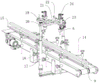
FIG. 1 is a schematic structural diagram of an appearance of a two-channel independent filling mechanism;
fig. 2 is a schematic structural view of the appearance of the dual-channel independent filling mechanism, showing another view angle of the dual-channel independent filling mechanism.
In the figure: 1. a frame; 2. a drive motor; 3. a drive belt; 4. a filling assembly; 5. a filling frame; 6. a filling head; 7. a rotating shaft; 8. an isolation frame; 9. a guide surface; 10. a fixed mount; 12. positioning the bolt; 13. a cross bar; 14. an "L" shaped support frame; 15. a limiting rod; 16. rotating the grip; 17. a first connecting rod; 18. a second connecting rod; 19. a turntable; 20. connecting blocks; 21. a connecting plate; 22. a slide hole; 23. a butt joint plate; 24. a driving cylinder; 25. a vertical rod.
Detailed Description
The present invention will be described in further detail with reference to the accompanying drawings.
Referring to fig. 1 and 2, a two-channel independent filling mechanism comprises a frame 1, wherein driving motors 2 are respectively arranged on two sides of the frame 1, driving belts 3 are connected to output shafts of the driving motors 2 in a transmission mode, filling assemblies 4 are arranged on the upper sides of the driving belts 3, and each filling assembly 4 comprises a filling frame 5 and a filling head 6.
The upper end of the frame 1 is horizontal, the driving motor 2 is fixed at two sides of the frame 1 through bolts, the driving ends of the two driving motors 2 are oppositely arranged, two ends of the frame 1 are respectively connected with a rotating shaft 7 in a rotating mode, the driving belts 3 are totally two, the driving belts are parallel to each other, the two ends of each driving belt 3 are in interference fit with the side ends of the rotating shaft 7, the upper end of each driving belt 3 is horizontal and rotatable, the output shaft of the driving motor 2 is connected to the rotating shaft 7, and the driving motors 2 can drive the driving belts 3 to rotate.
A gap is reserved between the two driving belts 3, the machine frame 1 is connected with an isolation frame 8 between the two driving belts 3 through bolts, the isolation frame 8 is parallel to and perpendicular to the driving belts 3, and one end of the isolation frame 8 is provided with an inclined guide surface 9.
The two sides of the rack 1 are connected with a plurality of fixing frames 10 through bolts, one ends of the fixing frames 10, which are far away from each other, are vertically slid and inserted with vertical rods 25, the fixing frames 10 are in threaded connection with positioning bolts 12, and one ends of the positioning bolts 12 are abutted against the side ends of the vertical rods 25 to fix the fixing frames.
The upper end of the vertical rod is higher than the upper end of the driving belt 3, the upper end of the vertical rod is horizontally slid and inserted with a cross rod 13, the upper end of the vertical rod 25 is in threaded connection with a positioning bolt 12, one end of the positioning bolt 12 abuts against the side end of the cross rod 13 so as to fix the cross rod 13, meanwhile, the cross rod 13 is perpendicular to the isolation frame 8, and the cross rod 13 and the vertical rod 25 form an L-shaped support frame 14.
The end of the cross rod 13 far away from the vertical rod is fixed with a limiting rod 15 through a bolt, and the two limiting rods 15 are parallel to each other and are parallel to the isolation frame 8.
A turning handle 16 is welded to one end of the positioning bolt 12 so that the positioning bolt 12 can be manually tightened or loosened.
The filling frame 5 comprises two first connecting rods 17 fixed at the side end of the frame 1, first connecting rods 17 and a second connecting rod 18 inserted into the upper end of the first connecting rods 17 in a sliding mode, the first connecting rods 17 and the second connecting rods 18 are vertical, a set of threaded connection is arranged between the two sets of first connecting rods 17 and the second connecting rods 18, the upper end of each second connecting rod 18 is connected with a rotating disc 19 through bolts, the second connecting rods 18 slide into the first connecting rods 17 through the rotating discs 19, and the effect of adjusting the height of the filling frame 5 is achieved. The lower end of the rotary table 19 is rotatably connected with a connecting block 20 through a bearing, a connecting plate 21 is welded between the connecting block 20 and the other second connecting rod 18, and the connecting plate 21 is horizontal and vertical to the isolation frame 8.
The long-strip-shaped sliding hole 22 is formed in the upper end of the connecting plate 21, the connecting plate 21 is connected with two abutting plates 23 in a sliding mode through bolts at the sliding hole 22, the upper end of each abutting plate 23 is connected with a driving air cylinder 24 through a bolt, a piston rod of each driving air cylinder 24 vertically penetrates through the abutting plates 23 downwards, and the filling head 6 is fixed at the lower end of the piston rod of each driving air cylinder 24 through a bolt and can be driven by the driving air cylinder 24.
The implementation principle of the embodiment is as follows:
carry the filling as required through this independent filling mechanism of binary channels, determine earlier what of bottle, thereby decide binary channels synchronous working, still independent work, simultaneously according to the size regulation horizontal pole 13 of body and the position of montant 25, and the length of second connecting rod 18 pegging graft in head rod 17 and the horizontal position of filling head 6, make driving motor 2 begin to work this moment, driving belt 3 begins the transmission, put into the bottle by guide face 9 one end, the bottle moves under driving belt 3's drive and gag lever post 15 and spacer 8's spacing, when removing to filling subassembly 4 lower extreme, drive actuating cylinder 24 makes the lower extreme of filling head 6 insert the filling in the bottleneck, after the filling, raise filling head 6, driving belt 3 removes the bottle that the filling was ended to the other end of frame 1.
The embodiment of this specific implementation mode is the preferred embodiment of the present invention, not limit according to this the utility model discloses a protection scope, so: all equivalent changes made according to the structure, shape and principle of the utility model are covered within the protection scope of the utility model.
Claims (8)
1. The utility model provides a two-channel independent filling mechanism, includes frame (1), its characterized in that: frame (1) both sides respectively are provided with driving motor (2), two driving motor (2) set up in opposite directions, the output shaft transmission of driving motor (2) is connected with driving belt (3), two driving belt (3) are parallel to each other, two be provided with isolation frame (8) between driving belt (3), isolation frame (8) both sides are provided with gag lever post (15), isolation frame (8) upside is provided with filling subassembly (4).
2. The dual channel self-contained filling apparatus of claim 1, wherein: one end of the limiting rod (15) far away from each other is provided with a plurality of L-shaped supporting frames (14), the side end of the rack (1) is provided with a plurality of fixing frames (10), and the lower ends of the L-shaped supporting frames (14) vertically slide and are inserted into one end of each fixing frame (10).
3. The dual channel self-contained filling apparatus of claim 2, wherein: the L-shaped support frame (14) comprises a vertical rod (25) which is slidably inserted at one end of the fixing frame (10), and a cross rod (13) of which one end is fixed at the side end of the limiting rod (15) and the other end is slidably inserted at the upper end of the vertical rod (25).
4. The dual channel self-contained filling mechanism of claim 3, wherein: the upper end of the vertical rod (25) and the side end of the fixing frame (10) are provided with positioning bolts (12), one end of each positioning bolt (12) is abutted to the side end of the transverse rod (13) and the vertical rod (25), and the other end of each positioning bolt is provided with a rotating handle (16).
5. The dual channel self-contained filling mechanism of claim 4, wherein: the filling assembly (4) comprises a filling frame (5) and a filling head (6), wherein the filling frame (5) extends upwards from the side end of the rack (1), and the filling head (6) is horizontally arranged on the upper end of the filling frame (5) in a sliding mode.
6. The dual channel self-contained filling mechanism of claim 5, wherein: the filling frame (5) comprises two first connecting rods (17), second connecting rods (18) which are inserted in a sliding mode at the upper ends of the first connecting rods (17), and connecting plates (21) which are arranged between the two second connecting rods (18).
7. The dual channel self-contained filling mechanism of claim 6, wherein: and a driving air cylinder (24) for driving the filling head (6) to move along the vertical direction is arranged at the upper end of the filling head.
8. The dual channel self-contained filling mechanism of claim 7, wherein: one end of the isolation frame (8) is close to two sides of the limiting rod (15) and is provided with an inclined guide surface (9).
Priority Applications (1)
| Application Number | Priority Date | Filing Date | Title |
|---|---|---|---|
| CN202020233353.7U CN211770224U (en) | 2020-02-28 | 2020-02-28 | Double-channel independent filling mechanism |
Applications Claiming Priority (1)
| Application Number | Priority Date | Filing Date | Title |
|---|---|---|---|
| CN202020233353.7U CN211770224U (en) | 2020-02-28 | 2020-02-28 | Double-channel independent filling mechanism |
Publications (1)
| Publication Number | Publication Date |
|---|---|
| CN211770224U true CN211770224U (en) | 2020-10-27 |
Family
ID=72903162
Family Applications (1)
| Application Number | Title | Priority Date | Filing Date |
|---|---|---|---|
| CN202020233353.7U Expired - Fee Related CN211770224U (en) | 2020-02-28 | 2020-02-28 | Double-channel independent filling mechanism |
Country Status (1)
| Country | Link |
|---|---|
| CN (1) | CN211770224U (en) |
-
2020
- 2020-02-28 CN CN202020233353.7U patent/CN211770224U/en not_active Expired - Fee Related
Similar Documents
| Publication | Publication Date | Title |
|---|---|---|
| CN112846371A (en) | Steel pipe machining feeding machine | |
| CN206069319U (en) | A kind of automatic capping machine | |
| CN110745531A (en) | Automatic arrangement machine | |
| CN211770224U (en) | Double-channel independent filling mechanism | |
| CN209453715U (en) | A kind of saw material device | |
| CN110775870A (en) | Screw rod elevator | |
| CN108438361A (en) | A kind of cartoning sealing machine | |
| CN209537301U (en) | A kind of scribing machine of fly-cutting | |
| CN209052053U (en) | Bearing base feeding device | |
| CN208117315U (en) | A kind of fixed device of door of elevator processing | |
| CN109589613A (en) | It is a kind of for electronic toy processing accessory group connect equipped equipment and its working method | |
| CN109760874A (en) | A kind of clamping conveying device of box erecting machine | |
| CN212886719U (en) | Glass feeding guide mechanism of glass edge grinding machine | |
| CN213386168U (en) | Raw material transfer device is used in production of plastic bottle aluminium system lid | |
| US5373880A (en) | Method of continuously processing chopsticks as well as an apparatus for carrying out the method | |
| CN211480104U (en) | Power battery transmission device and production line applying same | |
| CN111590692A (en) | Wooden floor cutting equipment and working method thereof | |
| CN216784004U (en) | Conveying path adjusting device for product conveying | |
| CN213369645U (en) | Automatic moon cake arranging machine | |
| CN218267059U (en) | Agricultural machinery transmission | |
| CN113526144B (en) | Silicon steel sheet balanced stacking and distributing system | |
| CN211365114U (en) | Product connects material to fold a packet device | |
| CN213950548U (en) | Bottling device for producing liqueur | |
| CN216971982U (en) | 1-methylcyclopropene liquid filling device | |
| CN209906327U (en) | Full-automatic oral liquid filling machine |
Legal Events
| Date | Code | Title | Description |
|---|---|---|---|
| GR01 | Patent grant | ||
| GR01 | Patent grant | ||
| CF01 | Termination of patent right due to non-payment of annual fee |
Granted publication date: 20201027 |
|
| CF01 | Termination of patent right due to non-payment of annual fee |