CN211763160U - Injection molding machining is with mould of taking positioner - Google Patents
Injection molding machining is with mould of taking positioner Download PDFInfo
- Publication number
- CN211763160U CN211763160U CN202020221402.5U CN202020221402U CN211763160U CN 211763160 U CN211763160 U CN 211763160U CN 202020221402 U CN202020221402 U CN 202020221402U CN 211763160 U CN211763160 U CN 211763160U
- Authority
- CN
- China
- Prior art keywords
- bottom plate
- fixedly connected
- injection molding
- fly leaf
- mould
- Prior art date
- Legal status (The legal status is an assumption and is not a legal conclusion. Google has not performed a legal analysis and makes no representation as to the accuracy of the status listed.)
- Expired - Fee Related
Links
- 238000001746 injection moulding Methods 0.000 title claims abstract description 27
- 238000003754 machining Methods 0.000 title description 2
- 238000012545 processing Methods 0.000 abstract description 6
- 230000008901 benefit Effects 0.000 abstract description 3
- 229920003023 plastic Polymers 0.000 abstract description 2
- 239000004033 plastic Substances 0.000 abstract description 2
- 238000000034 method Methods 0.000 description 8
- 230000008569 process Effects 0.000 description 5
- 230000009471 action Effects 0.000 description 3
- 238000006243 chemical reaction Methods 0.000 description 3
- 238000004519 manufacturing process Methods 0.000 description 2
- 230000007246 mechanism Effects 0.000 description 2
- 238000000465 moulding Methods 0.000 description 2
- 239000002994 raw material Substances 0.000 description 2
- 230000004075 alteration Effects 0.000 description 1
- 230000009286 beneficial effect Effects 0.000 description 1
- 230000006835 compression Effects 0.000 description 1
- 238000007906 compression Methods 0.000 description 1
- 238000001816 cooling Methods 0.000 description 1
- 238000010586 diagram Methods 0.000 description 1
- 238000004512 die casting Methods 0.000 description 1
- 230000000694 effects Effects 0.000 description 1
- 230000007613 environmental effect Effects 0.000 description 1
- 238000002347 injection Methods 0.000 description 1
- 239000007924 injection Substances 0.000 description 1
- 238000009434 installation Methods 0.000 description 1
- 238000012986 modification Methods 0.000 description 1
- 230000004048 modification Effects 0.000 description 1
- 238000012805 post-processing Methods 0.000 description 1
- 238000002203 pretreatment Methods 0.000 description 1
- 238000006467 substitution reaction Methods 0.000 description 1
Images


Abstract
The utility model discloses an injection moulding is with mould of taking positioner, comprising a base plate, the top swing joint of bottom plate has the body, the rear side fixedly connected with locating plate at bottom plate top, the front side swing joint at bottom plate top has the fly leaf, two canceling release mechanical systems of inner wall fixedly connected with of bottom plate, the equal swing joint in both sides of fly leaf has spacing frame. The utility model discloses a set up the bottom plate, a body, the locating plate, the fly leaf, canceling release mechanical system, spacing frame, the gag lever post, the dovetail piece, the dovetail, the slide bar, the cooperation of mounting hole and limiting plate is used, it is not convenient for carry on spacing fixedly to the die holder to have solved current mould for injection molding, the user needs use tool and fixing bolt to fix a position the die holder, fixed complex operation, the problem that the user of being not convenient for uses, this mould plastics processing is with taking positioner's mould, possess the advantage of being convenient for advance line location to the die holder.
Description
Technical Field
The utility model belongs to the technical field of injection mold, especially, relate to an injection molding is with mould of taking positioner.
Background
Injection molding is a method for producing and molding industrial products, and the products generally adopt rubber injection molding and plastic injection molding, and the injection molding can also be divided into injection molding and die casting methods.
The injection molding processing process is a complex processing flow which relates to various factors such as mold design, mold manufacturing, raw material characteristics, a raw material pretreatment method, a molding process, injection molding machine operation and the like and is closely related to processing environmental conditions, product cooling time and a post-processing process, and the problems in the prior art are as follows: the mould for injection molding processing is not convenient for carry on spacing fixedly to the die holder, and the user needs use tools and fixing bolt to fix a position the die holder, and fixed operation is loaded down with trivial details, and the not convenient to use person uses.
SUMMERY OF THE UTILITY MODEL
Problem to prior art exists, the utility model provides an injection moulding is with mould of taking positioner possesses the advantage that is convenient for advance line location to the die holder, has solved that current injection moulding is with mould and is not convenient for carry on spacing fixedly to the die holder, and the user needs use tools and fixing bolt to fix a position the die holder, and fixed complex operation is not convenient for the user to carry out the problem of using.
The utility model discloses a realize like this, a mould of taking positioner for injection moulding, comprising a base plate, the top swing joint of bottom plate has the body, the rear side fixedly connected with locating plate at bottom plate top, the front side swing joint at bottom plate top has the fly leaf, two canceling release mechanical systems of inner wall fixedly connected with of bottom plate, the equal swing joint in both sides of fly leaf has spacing frame, the equal fixedly connected with in both sides at bottom plate top and the gag lever post that spacing frame cooperation was used.
As the utility model discloses it is preferred, canceling release mechanical system includes the spring, the front side of spring and the inner wall fixed connection of bottom plate, the rear side fixedly connected with movable rod of spring, the logical groove of using with the movable rod cooperation is seted up at the top of bottom plate, the top of movable rod pass logical groove and with fly leaf fixed connection.
As the utility model discloses preferred, the equal fixedly connected with dovetail block in one side that two spacing frames are relative, the dovetail that uses with the cooperation of dovetail block is all seted up to the both sides of fly leaf.
As the utility model discloses it is preferred, two slide bars of inner wall fixedly connected with of bottom plate, the surface of slide bar is located to spring and movable rod all cover.
As the utility model discloses it is preferred, the bottom fixedly connected with slider of movable rod, the spout that uses with the slider cooperation is seted up to the bottom of bottom plate inner wall.
As the utility model discloses it is preferred, the mounting hole has all been seted up in the four corners at bottom plate top, the equal fixedly connected with limiting plate in both sides at bottom plate top.
Compared with the prior art, the beneficial effects of the utility model are as follows:
1. the utility model solves the problems that the prior mould for injection molding is inconvenient to limit and fix the lower die holder, a user needs to position the lower die holder by using a tool and a fixing bolt, the fixing operation is complex, and the use is inconvenient for the user, this mould of taking positioner for injection moulding processing possesses the advantage of being convenient for fix a position the die holder.
2. The utility model discloses a set up canceling release mechanical system, can exert reaction force to the fly leaf, drive the fly leaf and remove backward and body in close contact with, carry out spacing fixed to the body, improved the utility model discloses a steadiness.
3. The utility model discloses a set up dovetail and dovetail, be convenient for drive spacing frame and reciprocate and use with the gag lever post cooperation and carry on spacingly to the fly leaf, effectually avoided in the use, the body receives external force to drive the fly leaf back-and-forth movement, can't fix a position the body.
4. The utility model discloses a set up the slide bar, the effectual stationarity that improves the movable rod back-and-forth movement takes place the incline when effectually having avoided the movable rod to remove, and then drives the spring and takes place the slope, causes certain damage to the spring.
5. The utility model discloses a set up slider and spout, improved the stationarity of movable rod back-and-forth movement, simultaneously the effectual frictional force that has reduced between movable rod and the bottom plate has increased the utility model discloses a life.
6. The utility model discloses a set up the mounting hole, convenient to use person uses through fixing bolt and mounting hole cooperation, installs fixedly to the bottom plate, has improved the utility model discloses a convenience through setting up the limiting plate, effectually carries on spacingly to the body, has avoided the body atress to remove.
Drawings
Fig. 1 is a schematic structural diagram provided in an embodiment of the present invention;
FIG. 2 is a right side sectional view of a partial structure of a base plate according to an embodiment of the present invention;
fig. 3 is an enlarged view of a according to an embodiment of the present invention;
fig. 4 is a top sectional view of a partial structure of a movable plate according to an embodiment of the present invention.
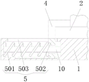
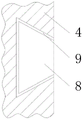
In the figure: 1. a base plate; 2. a body; 3. positioning a plate; 4. a movable plate; 5. a reset mechanism; 501. a spring; 502. a movable rod; 503. a through groove; 6. a limiting frame; 7. a limiting rod; 8. a dovetail block; 9. a dovetail groove; 10. a slide bar; 11. mounting holes; 12. and a limiting plate.
Detailed Description
In order to further understand the contents, features and effects of the present invention, the following embodiments are illustrated and described in detail with reference to the accompanying drawings.
The structure of the present invention will be described in detail with reference to the accompanying drawings.
As shown in fig. 1 to 4, the embodiment of the utility model provides a pair of mould of taking positioner for injection molding, including bottom plate 1, the top swing joint of bottom plate 1 has body 2, the rear side fixedly connected with locating plate 3 at 1 top of bottom plate, and the front side swing joint at 1 top of bottom plate has fly leaf 4, two canceling release mechanical system 5 of inner wall fixedly connected with of bottom plate 1, and the equal swing joint in both sides of fly leaf 4 has spacing frame 6, and the equal fixedly connected with in both sides at 1 top of bottom plate cooperates gag lever post 7 that uses with spacing frame 6.
Referring to fig. 2, the reset mechanism 5 includes a spring 501, a front side of the spring 501 is fixedly connected to an inner wall of the bottom plate 1, a movable rod 502 is fixedly connected to a rear side of the spring 501, a through groove 503 matched with the movable rod 502 is formed in the top of the bottom plate 1, and the top of the movable rod 502 penetrates through the through groove 503 and is fixedly connected to the movable plate 4.
Adopt above-mentioned scheme: through setting up canceling release mechanical system 5, can apply reaction force to fly leaf 4, drive fly leaf 4 backward movement and body 2 in close contact with, carry out spacing fixed to body 2, improved the utility model discloses a steadiness.
Referring to fig. 4, one side of each of the two limiting frames 6 opposite to each other is fixedly connected with a dovetail block 8, and dovetail grooves 9 matched with the dovetail blocks 8 for use are formed in the two sides of the movable plate 4.
Adopt above-mentioned scheme: through setting up dovetail block 8 and dovetail 9, be convenient for drive spacing frame 6 and reciprocate and use with the cooperation of gag lever post 7 and carry out spacingly to fly leaf 4, effectually avoided in the use, body 2 receives external force to drive fly leaf 4 back-and-forth movement, can't fix a position body 2.
Referring to fig. 2, two sliding rods 10 are fixedly connected to the inner wall of the base plate 1, and a spring 501 and a movable rod 502 are sleeved on the surfaces of the sliding rods 10.
Adopt above-mentioned scheme: through setting up slide bar 10, the effectual stationarity that has improved the back-and-forth movement of movable rod 502 has effectually avoided taking place the incline when movable rod 502 removes, and then drives spring 501 and takes place the slope, causes certain damage to spring 501.
Referring to fig. 2, a sliding block is fixedly connected to the bottom of the movable rod 502, and a sliding groove matched with the sliding block is formed in the bottom of the inner wall of the bottom plate 1.
Adopt above-mentioned scheme: through setting up slider and spout, improved the stationarity of movable rod 502 back-and-forth movement, simultaneously the effectual frictional force that reduces between movable rod 502 and the bottom plate 1 has increased the utility model discloses a life.
Referring to fig. 1, mounting holes 11 are formed at four corners of the top of the bottom plate 1, and limiting plates 12 are fixedly connected to two sides of the top of the bottom plate 1.
Adopt above-mentioned scheme: through setting up mounting hole 11, convenient to use person uses through fixing bolt and the 11 cooperations of mounting hole, installs fixedly bottom plate 1, has improved the utility model discloses a convenience through setting up limiting plate 12, effectually carries on spacingly to body 2, has avoided the body 2 atress to remove about.
The utility model discloses a theory of operation:
when using, the user need fix a position body 2, can be earlier fixed to suitable position with bottom plate 1 installation, then place body 2 on bottom plate 1, promote body 2 to locating plate 3 and bottom plate 1 in close contact with backward, then control spacing frame 6 rebound to break away from with gag lever post 7, the reaction force is applyed to the movable rod 502 to the spring 501 of compression, drive movable rod 502 rebound, and then drive fly leaf 4 rebound and body 2 in close contact with, then the rebound spacing frame 6 passes spacing frame 6 to gag lever post 7, spacing fly leaf 4, and then fix a position body 2, improved the utility model discloses a practicality.
In summary, the following steps: this injection moulding is with mould of taking positioner, through setting up bottom plate 1, body 2, locating plate 3, fly leaf 4, canceling release mechanical system 5, spacing frame 6, gag lever post 7, dovetail piece 8, dovetail 9, slide bar 10, the cooperation of mounting hole 11 and limiting plate 12 is used, it is not convenient for carry on spacing fixedly to the die holder to have solved current injection moulding for the mould, the user needs use tools and fixing bolt to fix a position the die holder, the fixed operation is loaded down with trivial details, the problem that the person of not being convenient for uses.
It is noted that, herein, relational terms such as first and second, and the like may be used solely to distinguish one entity or action from another entity or action without necessarily requiring or implying any actual such relationship or order between such entities or actions. Also, the terms "comprises," "comprising," or any other variation thereof, are intended to cover a non-exclusive inclusion, such that a process, method, article, or apparatus that comprises a list of elements does not include only those elements but may include other elements not expressly listed or inherent to such process, method, article, or apparatus.
Although embodiments of the present invention have been shown and described, it will be appreciated by those skilled in the art that changes, modifications, substitutions and alterations can be made in these embodiments without departing from the principles and spirit of the invention, the scope of which is defined in the appended claims and their equivalents.
Claims (6)
1. The utility model provides an injection moulding is with mould of taking positioner, includes bottom plate (1), its characterized in that: the top swing joint of bottom plate (1) has body (2), rear side fixedly connected with locating plate (3) at bottom plate (1) top, the front side swing joint at bottom plate (1) top has fly leaf (4), two canceling release mechanical system (5) of inner wall fixedly connected with of bottom plate (1), the equal swing joint in both sides of fly leaf (4) has spacing frame (6), the equal fixedly connected with in both sides at bottom plate (1) top and spacing pole (7) that spacing frame (6) cooperation was used.
2. The mold with a positioning device for injection molding according to claim 1, wherein: canceling release mechanical system (5) include spring (501), the front side of spring (501) and the inner wall fixed connection of bottom plate (1), the rear side fixedly connected with movable rod (502) of spring (501), logical groove (503) that use with movable rod (502) cooperation are seted up at the top of bottom plate (1), the top of movable rod (502) is passed logical groove (503) and with fly leaf (4) fixed connection.
3. The mold with a positioning device for injection molding according to claim 1, wherein: the two limiting frames (6) are opposite to each other, one side of each limiting frame is fixedly connected with a dovetail block (8), and dovetail grooves (9) matched with the dovetail blocks (8) for use are formed in the two sides of the movable plate (4).
4. The mold with a positioning device for injection molding according to claim 2, wherein: the inner wall of the bottom plate (1) is fixedly connected with two sliding rods (10), and the spring (501) and the movable rod (502) are both sleeved on the surfaces of the sliding rods (10).
5. The mold with a positioning device for injection molding according to claim 2, wherein: the bottom fixedly connected with slider of movable rod (502), the spout that uses with the slider cooperation is seted up to the bottom of bottom plate (1) inner wall.
6. The mold with a positioning device for injection molding according to claim 1, wherein: mounting holes (11) are formed in four corners of the top of the bottom plate (1), and limiting plates (12) are fixedly connected to two sides of the top of the bottom plate (1).
Priority Applications (1)
| Application Number | Priority Date | Filing Date | Title |
|---|---|---|---|
| CN202020221402.5U CN211763160U (en) | 2020-02-27 | 2020-02-27 | Injection molding machining is with mould of taking positioner |
Applications Claiming Priority (1)
| Application Number | Priority Date | Filing Date | Title |
|---|---|---|---|
| CN202020221402.5U CN211763160U (en) | 2020-02-27 | 2020-02-27 | Injection molding machining is with mould of taking positioner |
Publications (1)
| Publication Number | Publication Date |
|---|---|
| CN211763160U true CN211763160U (en) | 2020-10-27 |
Family
ID=72909630
Family Applications (1)
| Application Number | Title | Priority Date | Filing Date |
|---|---|---|---|
| CN202020221402.5U Expired - Fee Related CN211763160U (en) | 2020-02-27 | 2020-02-27 | Injection molding machining is with mould of taking positioner |
Country Status (1)
| Country | Link |
|---|---|
| CN (1) | CN211763160U (en) |
-
2020
- 2020-02-27 CN CN202020221402.5U patent/CN211763160U/en not_active Expired - Fee Related
Similar Documents
| Publication | Publication Date | Title |
|---|---|---|
| CN211542521U (en) | Die punch device of electronic product | |
| CN211763160U (en) | Injection molding machining is with mould of taking positioner | |
| CN111531043A (en) | Mould with conveniently fix a position installation function | |
| CN210173750U (en) | Positioning and punching device for plastic product production | |
| CN110756609A (en) | Forming outlet die for aluminum bar processing | |
| CN211890525U (en) | Clamping device is used in injection molding processing | |
| CN214645547U (en) | Core pulling device of injection mold | |
| CN212945026U (en) | Quick die change device | |
| CN214188285U (en) | But rapid prototyping's cell-phone inner panel injection mold | |
| CN210679559U (en) | Injection mold convenient to take off material | |
| CN211416136U (en) | Electronic cover plate injection mold | |
| CN211889928U (en) | Frock clamp is used in water pump mold processing | |
| CN212045722U (en) | Injection mold convenient to maintain | |
| CN210617212U (en) | Cooling device of plastic mould | |
| CN209158750U (en) | A kind of full-computerized injection molding machine that injection molding mould plate is conveniently replaceable | |
| CN212528500U (en) | Positioning mechanism of injection mold | |
| CN211891607U (en) | Mold for transparent shield | |
| CN212528834U (en) | Die convenient to fix | |
| CN220781446U (en) | Mould cleaning device with adaptability | |
| CN213321340U (en) | Injection mold for plastic production | |
| CN219903119U (en) | Injection mold | |
| CN214562618U (en) | Injection mold is used in lid processing behind casing | |
| CN217293206U (en) | Injection molding equipment for injection molding process | |
| CN214419390U (en) | High-numerical-control injection molding machine for high-corrosion-resistant floating ball | |
| CN219256340U (en) | Slide demoulding assembly for improving mould opening efficiency of mould |
Legal Events
| Date | Code | Title | Description |
|---|---|---|---|
| GR01 | Patent grant | ||
| GR01 | Patent grant | ||
| CF01 | Termination of patent right due to non-payment of annual fee |
Granted publication date: 20201027 |
|
| CF01 | Termination of patent right due to non-payment of annual fee |