CN211743612U - Wall-mounted air conditioner connecting wire set - Google Patents
Wall-mounted air conditioner connecting wire set Download PDFInfo
- Publication number
- CN211743612U CN211743612U CN202020711109.7U CN202020711109U CN211743612U CN 211743612 U CN211743612 U CN 211743612U CN 202020711109 U CN202020711109 U CN 202020711109U CN 211743612 U CN211743612 U CN 211743612U
- Authority
- CN
- China
- Prior art keywords
- clamping
- plug
- plug main
- plastic
- main body
- Prior art date
- Legal status (The legal status is an assumption and is not a legal conclusion. Google has not performed a legal analysis and makes no representation as to the accuracy of the status listed.)
- Active
Links
Images


Landscapes
- Multi-Conductor Connections (AREA)
Abstract
The utility model discloses a wall-mounted air conditioner connecting wire group, including plastic plug, plastics fastener, three conductor wires, the left and right sides both ends of three conductor wires respectively are connected with a plastic plug, the plastics fastener is installed on the plastics plug, the plastic plug includes clamp plate, plug main part, the clamp plate is installed at the top of plug main part, the front end bottom of clamp plate is equipped with the toper fixture block, the top both sides of plug main part respectively are equipped with a cardboard, the front end of cardboard is equipped with a toper ka tai, be equipped with two slots in the middle of the top of plug main part, two slots parallel arrangement, the middle part of plug main part is equipped with three terminal jack; the utility model has the advantages of reasonable design, connect convenient, connect more firmly.
Description
Technical Field
The utility model relates to a conductive connection device especially relates to wall-hanging air conditioner connection line group.
Background
The connection line is a conductive line for connection between devices or between devices and circuits or the like. Traditional wire adopts the welded mode to connect, and connection speed is slow, needs more workman to participate in, and this cost of people is higher, and in addition, current wire connecting piece is because structural design is unreasonable, connects it too conveniently.
Disclosure of Invention
In order to overcome the defects of the prior art, the utility model provides a wall-mounted air conditioner connecting line group which has reasonable structural design, convenient connection and firmer connection.
A wall-mounted air conditioner connecting wire set comprises a plastic plug, plastic clamping pieces and three conducting wires, wherein the left end and the right end of each conducting wire are respectively connected with the plastic plug, the plastic clamping pieces are arranged on the plastic plug, the plastic plug comprises a pressing plate and a plug main body, the pressing plate is arranged at the top of the plug main body, a conical clamping block is arranged at the bottom of the front end of the pressing plate, two clamping plates are respectively arranged on two sides of the top of the plug main body, a conical clamping table is arranged at the front end of each clamping plate, two inserting grooves are arranged in the middle of the top of the plug main body in parallel, three terminal inserting holes are arranged in the middle of the plug main body, two positioning plates are arranged above the terminal inserting holes, conductive terminals of the three conducting wires are inserted into the terminal inserting holes, each plastic clamping piece comprises three T-shaped clamping columns, three square clamping columns and two clamping grooves, the square clamping columns are inserted into the terminal insertion holes, and clamping grooves and clamping tables are arranged in the two clamping grooves.
The three T-shaped clamping columns and the three square clamping columns are arranged in parallel up and down, and the shapes and the sizes of the three square clamping columns are matched with the three terminal jacks.
The utility model has the advantages that: the utility model relates to a rationally, mainly constitute by plastics plug, plastics fastener, three conductor wires. The copper cores of the three conducting wires are inserted into the metal fixing rings of the metal conducting terminals, then the metal fixing rings are pressed and deformed by a machine, so that the copper cores are fixed on the metal conducting terminals, the metal conducting terminals are inserted into the terminal insertion holes, the T-shaped clamping columns are inserted into the T-shaped grooves formed between the two positioning plates, the square clamping columns are inserted into the terminal insertion holes, and therefore the conducting terminals and the conducting wires are fixed in the plastic plugs.
Drawings
The present invention will be further explained with reference to the drawings and examples.
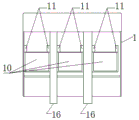
Fig. 1 is a schematic view of the overall structure of the present invention;
fig. 2 is a schematic top view of the plastic plug and the plastic fastener of the present invention after being disassembled;
fig. 3 is a schematic side view of the plastic plug and the plastic fastener of the present invention after being disassembled;
fig. 4 is a schematic back structural view of the plastic plug of the present invention;
fig. 5 is a schematic back structural view of the plastic fastener of the present invention.
Detailed Description
Referring to fig. 1-5, the wall-mounted air conditioner connection line set comprises a plastic plug 1, a plastic fastener 2 and three conductive wires 3, wherein the left end and the right end of each of the three conductive wires 3 are respectively connected with the plastic plug 1, copper cores of the three conductive wires 3 are inserted into metal fixing rings of metal conductive terminals, then the metal fixing rings are deformed by machine pressure, so that the copper cores are fixed in the metal fixing rings of the metal conductive terminals, the metal conductive terminals are inserted into terminal insertion holes to realize the connection of the plastic plug 1 and the conductive wires 3, the plastic fastener 2 is installed on the plastic plug 1, the plastic plug 1 comprises a pressure plate 4 and a plug main body 5, the pressure plate 4 is installed at the top of the plug main body 5 through a connecting plate, the bottom of the front end of the pressure plate 4 is provided with a conical fixture block 6, and the front end of the pressure plate 4 can, the tapered clamping block 6 is used for clamping a plastic socket on a circuit board, two sides of the top of the plug main body 5 are respectively provided with a clamping plate 7, the front end of the clamping plate 7 is provided with a tapered clamping table 8, the tapered clamping table 8 is provided with an insertion inclined plane, an insertion groove is formed between the two clamping plates 7 and is used for inserting the plastic socket, the tapered clamping table 8 is used for clamping the plastic socket, the middle of the top of the plug main body 5 is provided with two insertion grooves 9, the two insertion grooves 9 also play a role of guiding and are matched with plastic insertion strips on the plastic socket, the two insertion grooves 9 are arranged in parallel, the middle of the plug main body 5 is provided with three terminal insertion holes 10, two positioning plates 11 are arranged above the terminal insertion holes 10, a T-shaped groove is formed between the two positioning plates 11, a T-shaped clamping column is inserted into the T-shaped groove formed between the two positioning plates, the plastic clamping piece 2 comprises three T-shaped clamping columns 12, three square clamping columns 13 and two clamping grooves 14, the T-shaped clamping columns 12 are inserted between the two positioning plates 11, the square clamping columns 13 are inserted into the terminal insertion holes 10, and clamping grooves 15 are arranged in the two clamping grooves 14, and the clamping grooves 15 and the clamping grooves are used for clamping the front ends of two clamping ribs 16 at the bottom of the plug main body 5. The three T-shaped clamp posts 12 and the three square clamp posts 13 are arranged in parallel up and down, and the shape and the size of the three square clamp posts 13 are matched with the three terminal insertion holes 10. The utility model relates to a rationally, mainly constitute by plastics plug 1, plastics fastener 2, three conductor wire 3. The copper cores of the three conducting wires 3 are inserted into the metal fixing rings of the metal conducting terminals, then the metal fixing rings are pressed and deformed by a machine, so that the copper cores are fixed on the metal conducting terminals, the metal conducting terminals are inserted into the terminal insertion holes 10, then the T-shaped clamping columns 12 are inserted into T-shaped grooves formed between the two positioning plates 11, the square clamping columns 13 are inserted into the terminal insertion holes 10, and therefore the conducting terminals and the conducting wires 3 are fixed in the plastic plug 1.
Claims (2)
1. Wall-hanging air conditioner connecting wire group, including plastics plug, plastics fastener, three conductor wires, its characterized in that: the plastic plug comprises a pressing plate and a plug main body, the pressing plate is arranged at the top of the plug main body, a conical clamping block is arranged at the bottom of the front end of the pressing plate, two clamping plates are respectively arranged at two sides of the top of the plug main body, a conical clamping table is arranged at the front end of each clamping plate, two slots are arranged in the middle of the top of the plug main body in parallel, three terminal jacks are arranged in the middle of the plug main body, two positioning plates are arranged above the terminal jacks, conductive terminals of the three electric wires are inserted into the terminal jacks, the plastic clamping part comprises three T-shaped clamping columns, three square clamping columns and two clamping grooves, the T-shaped clamping columns are inserted between the two positioning plates, and the square clamping columns are inserted into the terminal jacks, and clamping groove clamping tables are arranged in the two clamping grooves.
2. A wall-mounted air conditioning connection block as defined in claim 1, wherein: the three T-shaped clamping columns and the three square clamping columns are arranged in parallel up and down, and the shapes and the sizes of the three square clamping columns are matched with the three terminal jacks.
Priority Applications (1)
| Application Number | Priority Date | Filing Date | Title |
|---|---|---|---|
| CN202020711109.7U CN211743612U (en) | 2020-05-05 | 2020-05-05 | Wall-mounted air conditioner connecting wire set |
Applications Claiming Priority (1)
| Application Number | Priority Date | Filing Date | Title |
|---|---|---|---|
| CN202020711109.7U CN211743612U (en) | 2020-05-05 | 2020-05-05 | Wall-mounted air conditioner connecting wire set |
Publications (1)
| Publication Number | Publication Date |
|---|---|
| CN211743612U true CN211743612U (en) | 2020-10-23 |
Family
ID=72852577
Family Applications (1)
| Application Number | Title | Priority Date | Filing Date |
|---|---|---|---|
| CN202020711109.7U Active CN211743612U (en) | 2020-05-05 | 2020-05-05 | Wall-mounted air conditioner connecting wire set |
Country Status (1)
| Country | Link |
|---|---|
| CN (1) | CN211743612U (en) |
-
2020
- 2020-05-05 CN CN202020711109.7U patent/CN211743612U/en active Active
Similar Documents
| Publication | Publication Date | Title |
|---|---|---|
| CN203951003U (en) | Movable socket | |
| CN211743612U (en) | Wall-mounted air conditioner connecting wire set | |
| CN105226419B (en) | A kind of binding post branch connector | |
| CN204538439U (en) | Aluminium alloy cable earth connection terminal crimping mold | |
| CN203180295U (en) | Wiring terminal riveting tooling | |
| CN204497398U (en) | A kind of clamping type LED binding post and electric wire connecting junction thereof | |
| CN202695941U (en) | Crimping die for wire harness multigang terminal | |
| CN211743613U (en) | Air conditioner connecting line group | |
| CN215218339U (en) | Car wiring harness terminal tensile test machine | |
| CN211126376U (en) | Novel detachable socket | |
| CN211743606U (en) | Conductive connection wire group | |
| CN210670887U (en) | High-power wireless controller shell structure of electric vehicle | |
| CN203014000U (en) | Air-conditioning outdoor unit wiring assembly | |
| CN211743611U (en) | Display panel connection line group | |
| CN208113076U (en) | A kind of wiring board of via hole equipped with convenient for being connect with component's feet | |
| CN210201108U (en) | Compressor connecting line set | |
| CN204966877U (en) | Quick binding post row of control by temperature change type | |
| CN108565569B (en) | Connecting terminal with stable connection | |
| CN210182744U (en) | Connecting wire assembly | |
| CN214849253U (en) | Conducting wire connector | |
| CN214505940U (en) | Plug-in wiring terminal for high-power electrical appliance | |
| CN217882110U (en) | Novel secondary plug-in components suitable for low-voltage distribution cabinet | |
| CN215645165U (en) | Modular socket structure | |
| CN219247038U (en) | A quick plug structure of plugging into for switching power supply | |
| CN210245749U (en) | Novel line ball frame binding post |
Legal Events
| Date | Code | Title | Description |
|---|---|---|---|
| GR01 | Patent grant | ||
| GR01 | Patent grant |