CN211735805U - Combined steel structure frame - Google Patents
Combined steel structure frame Download PDFInfo
- Publication number
- CN211735805U CN211735805U CN201921656498.1U CN201921656498U CN211735805U CN 211735805 U CN211735805 U CN 211735805U CN 201921656498 U CN201921656498 U CN 201921656498U CN 211735805 U CN211735805 U CN 211735805U
- Authority
- CN
- China
- Prior art keywords
- connecting block
- groove
- block
- rod
- fixedly connected
- Prior art date
- Legal status (The legal status is an assumption and is not a legal conclusion. Google has not performed a legal analysis and makes no representation as to the accuracy of the status listed.)
- Expired - Fee Related
Links
Images
Abstract
The utility model discloses a modular steel structural framework, including middle connecting block, horizontal pole and montant, the open slot has all been seted up to the middle-end of the middle connecting block left and right sides, the draw-in groove has been seted up to the lower extreme on open slot right side, the inner chamber of draw-in groove is pegged graft and is had the fixture block, the one end fixedly connected with second connecting block of draw-in groove is kept away from to the fixture block, the first connecting block of one end fixedly connected with of draw-in groove is kept away from to the second connecting block, the constant head tank has been seted up to the one end that the draw. The utility model discloses an effect of intermediate junction piece, horizontal pole, inserted bar, first connecting block, second connecting block, fixture block, draw-in groove, stopper and constant head tank to reached the purpose of being convenient for install, solved current combination formula steel structural framework and be not convenient for install, the staff need waste time and energy go to install steel structural framework, reduced work efficiency's problem.
Description
Technical Field
The utility model relates to a steel construction technical field specifically is a modular steel structural framework.
Background
The steel structure frame is a structure mainly made of steel, is one of main building structure types, and the steel has the characteristics of high strength, light dead weight and high rigidity, so the steel structure frame is particularly suitable for building large-span, ultrahigh and ultra-heavy buildings, belongs to an ideal elastomer, best meets the basic assumption of general engineering mechanics, has good material plasticity and toughness, can have larger deformation, and can well bear power load, the existing combined steel structure frame is inconvenient to install, and workers need to install the steel structure frame with time and labor waste, so the working efficiency is reduced, and therefore, the combined steel structure frame is provided.
SUMMERY OF THE UTILITY MODEL
An object of the utility model is to provide a modular steel structural framework to solve the problem that proposes among the above-mentioned background art.
In order to achieve the above object, the utility model provides a following technical scheme: the utility model provides a modular steel structural framework, includes intermediate junction piece, horizontal pole and montant, the open slot has all been seted up to the middle-end of the intermediate junction piece left and right sides, the draw-in groove has been seted up to the lower extreme on open slot right side, the inner chamber of draw-in groove is pegged graft and is had the fixture block, the one end fixedly connected with second connecting block of draw-in groove is kept away from to the fixture block, the first connecting block of one end fixedly connected with of draw-in groove is kept away from to the second connecting block, the constant head tank has been seted up to the one end that the draw-in groove was kept away from to first connecting block, the inner chamber of constant head tank is pegged graft and is had the inserted bar, the equal fixedly.
Preferably, the middle end of the left side of the cross rod is provided with an elongated slot, the upper end and the lower end of the elongated slot are both provided with sliding grooves, an inner cavity of each sliding groove is movably connected with a sliding block, one end, far away from the sliding grooves, of each sliding block is fixedly connected with a thin rod, and the lower end of the left side of the thin rod and the lower end of the right side of the cross rod are both fixedly connected with first connecting blocks.
Preferably, the through hole is formed in the middle end of the left side of the cross rod, and the thin rod is inserted into the inner cavity of the through hole.
Preferably, a through hole is formed in one end, far away from the vertical rod, of the middle connecting block, and an inserting rod is inserted into an inner cavity of the through hole.
Preferably, one end of the open slot, which is far away from the clamping block, is provided with a limiting slot.
Compared with the prior art, the beneficial effects of the utility model are as follows:
1. the utility model is provided with a middle connecting block, a horizontal rod, an inserting rod, a first connecting block, a second connecting block, a clamping groove, a limiting block and a positioning groove, when people need to install the steel structure frame, the first connecting block is only needed to be inserted into the open slot of the middle connecting block, then the horizontal rod is pulled outwards, the horizontal rod can drive the first connecting block to move outwards, the first connecting block can drive the clamping block to move outwards through the second connecting block while moving outwards, thereby the clamping block is clamped with the clamping groove, then the pressing rod is pressed downwards and rotated, the pressing rod can drive the inserting rod to rotate, the inserting rod can drive the limiting block to rotate while rotating, the limiting block is separated from the limiting groove, thereby the inserting rod is inserted into the positioning groove, the first connecting block is fixedly arranged on the middle connecting block, thereby the purpose of convenient installation is achieved, and the problem that the existing combined steel structure frame is inconvenient, the staff need waste time and energy go to install steel structural framework, has reduced work efficiency's problem.
2. The utility model discloses set up pin, slider and spout, slider on the pin can control in the spout and remove to make the pin remove about in the horizontal pole, thereby reached the purpose of length about adjustable this frame.
Drawings
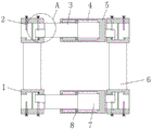
FIG. 1 is a schematic structural view of the present invention;
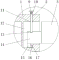
FIG. 2 is an enlarged schematic view of the structure at A of the present invention;
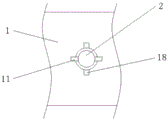
fig. 3 is a schematic view of the structure of the open slot in the bottom view state of the present invention.
In the figure: 1. a middle connecting block; 2. inserting a rod; 3. a thin rod; 4. a chute; 5. a cross bar; 6. a vertical rod; 7. a long groove; 8. a slider; 9. a pressure lever; 10. a spring; 11. a limiting block; 12. an open slot; 13. positioning a groove; 14. a first connection block; 15. a second connecting block; 16. a clamping block; 17. a card slot; 18. a limiting groove.
Detailed Description
The technical solutions in the embodiments of the present invention will be described clearly and completely with reference to the accompanying drawings in the embodiments of the present invention, and it is obvious that the described embodiments are only some embodiments of the present invention, not all embodiments. Based on the embodiments in the present invention, all other embodiments obtained by a person skilled in the art without creative work belong to the protection scope of the present invention.
In the description of the present invention, it is to be noted that, unless otherwise explicitly specified or limited, the terms "mounted", "provided", "connected", and the like are to be construed broadly, such as "connected", which may be fixedly connected, detachably connected, or integrally connected; can be mechanically or electrically connected; they may be connected directly or indirectly through intervening media, or they may be interconnected between two elements. The specific meaning of the above terms in the present invention can be understood in specific cases to those skilled in the art.
The utility model discloses an intermediate junction piece 1, inserted bar 2, slender pole 3, spout 4, horizontal pole 5, montant 6, elongated slot 7, slider 8, depression bar 9, spring 10, stopper 11, open slot 12, constant head tank 13, first connecting block 14, second connecting block 15, fixture block 16, draw-in groove 17 and spacing groove 18 part are the general standard or the part that technical staff in the field knows, and its structure and principle all are this technical staff and all can learn through the technical manual or learn through conventional experimental method.
Referring to fig. 1-3, a combined steel structure frame comprises a middle connecting block 1, a cross bar 5 and a vertical bar 6, wherein the middle end of the left side of the cross bar 5 is provided with an elongated slot 7, the upper and lower ends of the elongated slot 7 are both provided with sliding slots 4, the inner cavity of the sliding slot 4 is movably connected with a sliding block 8, one end of the sliding block 8 far away from the sliding slot 4 is fixedly connected with a thin bar 3, the lower end of the left side of the thin bar 3 and the lower end of the right side of the cross bar 5 are both fixedly connected with a first connecting block 14, the middle end of the left side of the cross bar 5 is provided with a through hole, the inner cavity of the through hole is inserted with the thin bar 3, the sliding block 8 on the thin bar 3 can move left and right in the sliding slot 4, so that the thin bar 3 can move left and right in the cross bar, and the inner cavity of the through hole is inserted with an inserting rod 2, the lower end of the right side of the opening groove 12 is provided with a clamping groove 17, the end of the opening groove 12 far away from the clamping block 16 is provided with a limiting groove 18, the inner cavity of the clamping groove 17 is inserted with a clamping block 16, the end of the clamping block 16 far away from the clamping groove 17 is fixedly connected with a second connecting block 15, the end of the second connecting block 15 far away from the clamping groove 17 is fixedly connected with a first connecting block 14, the end of the first connecting block 14 far away from the clamping groove 17 is provided with a positioning groove 13, the inner cavity of the positioning groove 13 is inserted with the inserting rod 2, the left end and the right end of the outer surface of the inserting rod 2 are both fixedly connected with limiting blocks 11, the end of the inserting rod 2 far away from the clamping groove 17 is fixedly connected with a pressure rod 9, when a steel structural frame needs to be installed, the first connecting block 14 only needs to be inserted into the opening groove 12 of the middle connecting block 1, thereby make fixture block 16 and draw-in groove 17 joint, then press and change depression bar 9 downwards, depression bar 9 can drive inserted bar 2 and rotate, inserted bar 2 can drive stopper 11 and rotate when the pivoted, make stopper 11 break away from spacing groove 18, thereby make inserted bar 2 insert constant head tank 13, make first connecting block 14 fixed mounting on middle connecting block 1, thereby reached the purpose of being convenient for install, the surface of inserted bar 2 and the one end that is close to depression bar 9 have cup jointed spring 10.
When the steel structure frame is required to be installed, people only need to insert the first connecting block 14 into the open slot 12 of the middle connecting block 1 and then pull the cross rod 5 outwards, the cross rod 5 can drive the first connecting block 14 to move outwards, the first connecting block 14 can drive the clamping block 16 to move outwards through the second connecting block 15 while moving outwards, so that the clamping block 16 is clamped with the slot 17, then the press rod 9 is pressed downwards and rotates, the press rod 9 can drive the inserting rod 2 to rotate, the inserting rod 2 can drive the limiting block 11 to rotate while rotating, the limiting block 11 is separated from the limiting slot 18, the inserting rod 2 is inserted into the positioning slot 13, the first connecting block 14 is fixedly installed on the middle connecting block 1, and the purpose of convenient installation is achieved, the problem of current combination formula steel structural framework be convenient for install not, the staff need waste time and energy go to install steel structural framework, reduced work efficiency is solved, has set up slim rod 3, slider 8 and spout 4, and slider 8 on the slim rod 3 can control in spout 4 and remove to make slim rod 3 remove about in horizontal pole 5, thereby reached the purpose of length about adjustable this frame.
Although embodiments of the present invention have been shown and described, it will be appreciated by those skilled in the art that changes, modifications, substitutions and alterations can be made in these embodiments without departing from the principles and spirit of the invention, the scope of which is defined in the appended claims and their equivalents.
Claims (5)
1. The utility model provides a modular steel structural framework, includes intermediate junction piece (1), horizontal pole (5) and montant (6), its characterized in that: open grooves (12) are respectively arranged at the middle ends of the left side and the right side of the middle connecting block (1), a clamping groove (17) is arranged at the lower end of the right side of the open groove (12), a clamping block (16) is inserted into the inner cavity of the clamping groove (17), one end of the clamping block (16) far away from the clamping groove (17) is fixedly connected with a second connecting block (15), one end of the second connecting block (15) far away from the clamping groove (17) is fixedly connected with a first connecting block (14), one end of the first connecting block (14) far away from the clamping groove (17) is provided with a positioning groove (13), an inserting rod (2) is inserted into the inner cavity of the positioning groove (13), the left end and the right end of the outer surface of the inserting rod (2) are fixedly connected with limiting blocks (11), one end of the inserted bar (2) far away from the clamping groove (17) is fixedly connected with a pressure bar (9), and one end of the outer surface of the inserted bar (2), which is close to the pressure bar (9), is sleeved with a spring (10).
2. A modular steel structural frame according to claim 1, wherein: an elongated slot (7) is formed in the middle end of the left side of the cross rod (5), sliding grooves (4) are formed in the upper end and the lower end of the elongated slot (7), a sliding block (8) is movably connected to the inner cavity of each sliding groove (4), one end, far away from each sliding groove (4), of each sliding block (8) is fixedly connected with a thin rod (3), and the lower end of the left side of each thin rod (3) and the lower end of the right side of the cross rod (5) are fixedly connected with a first connecting block (14).
3. A modular steel structural frame according to claim 1, wherein: the middle end of the left side of the cross rod (5) is provided with a through hole, and the inner cavity of the through hole is inserted with the thin rod (3).
4. A modular steel structural frame according to claim 1, wherein: the middle connecting block (1) is far away from one end of the vertical rod (6) and is provided with a through hole, and an inner cavity of the through hole is inserted with the inserted rod (2).
5. A modular steel structural frame according to claim 1, wherein: one end of the open slot (12) far away from the clamping block (16) is provided with a limiting slot (18).
Priority Applications (1)
| Application Number | Priority Date | Filing Date | Title |
|---|---|---|---|
| CN201921656498.1U CN211735805U (en) | 2019-09-30 | 2019-09-30 | Combined steel structure frame |
Applications Claiming Priority (1)
| Application Number | Priority Date | Filing Date | Title |
|---|---|---|---|
| CN201921656498.1U CN211735805U (en) | 2019-09-30 | 2019-09-30 | Combined steel structure frame |
Publications (1)
| Publication Number | Publication Date |
|---|---|
| CN211735805U true CN211735805U (en) | 2020-10-23 |
Family
ID=72849165
Family Applications (1)
| Application Number | Title | Priority Date | Filing Date |
|---|---|---|---|
| CN201921656498.1U Expired - Fee Related CN211735805U (en) | 2019-09-30 | 2019-09-30 | Combined steel structure frame |
Country Status (1)
| Country | Link |
|---|---|
| CN (1) | CN211735805U (en) |
Cited By (1)
| Publication number | Priority date | Publication date | Assignee | Title |
|---|---|---|---|---|
| CN112942869A (en) * | 2021-01-27 | 2021-06-11 | 关国荣 | Method for installing multi-layer large-span steel structure |
-
2019
- 2019-09-30 CN CN201921656498.1U patent/CN211735805U/en not_active Expired - Fee Related
Cited By (2)
| Publication number | Priority date | Publication date | Assignee | Title |
|---|---|---|---|---|
| CN112942869A (en) * | 2021-01-27 | 2021-06-11 | 关国荣 | Method for installing multi-layer large-span steel structure |
| CN112942869B (en) * | 2021-01-27 | 2023-09-08 | 关国荣 | Method for installing multi-layer large-span steel structure |
Similar Documents
| Publication | Publication Date | Title |
|---|---|---|
| CN211735805U (en) | Combined steel structure frame | |
| CN210621963U (en) | Connecting device for PC sunlight plate | |
| CN209958575U (en) | Interlocking type curtain wall plate and curtain wall | |
| CN215979009U (en) | Energy-saving curtain window level mounting structure | |
| CN215368062U (en) | Novel photovoltaic curtain wall dual-glass assembly | |
| CN212802134U (en) | Quick detach formula building curtain for building engineering | |
| CN208734089U (en) | A kind of component that aluminum alloy mould plate is connect with wooden model | |
| CN209071919U (en) | A kind of Contiuum type low-voltage distribution cabinet convenient for combination installation | |
| CN109095411B (en) | Indoor eminence installation work is with device | |
| CN210597716U (en) | Novel self-insulation wall structure | |
| CN212478184U (en) | Energy-saving assembled building wall | |
| CN214245063U (en) | Hot-pressing cutting device for clothes cutting | |
| CN206631977U (en) | A kind of device for separating batteries | |
| CN113756593B (en) | Adjusting and mounting structure and adjusting method for assembled aluminum plate curtain wall | |
| CN212715686U (en) | Green building roof is with decorating structure spare | |
| CN214403184U (en) | Energy-saving aluminum alloy door and window auxiliary frame mounting mechanism | |
| CN217153588U (en) | Automatic power-off energy-saving equipment for intelligent classroom | |
| CN213174368U (en) | Difficult not hard up building curtain connection structure | |
| CN218614787U (en) | Electric tool cutting machine based on ceramic tile cutting | |
| CN218771865U (en) | Photovoltaic building panel module | |
| CN219902041U (en) | Water electric iron wire box nail puller for constructional engineering | |
| CN210459193U (en) | Connecting structure of concrete pipe pile | |
| CN211183292U (en) | Bus duct fixing support frame | |
| CN211548252U (en) | Indoor curtain wall mounting structure capable of being conveniently disassembled and assembled | |
| CN212811169U (en) | Intelligent pipeline rack of light current |
Legal Events
| Date | Code | Title | Description |
|---|---|---|---|
| GR01 | Patent grant | ||
| GR01 | Patent grant | ||
| CF01 | Termination of patent right due to non-payment of annual fee | ||
| CF01 | Termination of patent right due to non-payment of annual fee |
Granted publication date: 20201023 Termination date: 20210930 |