Intelligent automatic feeding device of automobile brake
Technical Field
The utility model belongs to the technical field of the processing of automobile brake, especially, relate to an intelligent automatic feeding device of automobile brake.
Background
The automobile brake is used for forcibly decelerating or even stopping the running automobile according to the requirements of a driver, so that the stopped automobile can be stably parked under various road conditions (including on a slope), the speed of the automobile running on a downhill is kept stable, and the automobile brake has an important function for the safe running of the automobile. The automobile brake mainly comprises parts such as a steering knuckle, a mudguard, a bearing, a brake disc, a clamp spring, a hub unit, calipers and the like. In the process of constant-pressure installation of a traditional brake bearing and a hub unit, a part is placed on a steering knuckle manually, the part is pressed into the steering knuckle through automatic press-fitting equipment, the assembly of the part is completed, and therefore the part can be loaded through an automatic loading device during working, so that the labor intensity of workers and the working efficiency are saved.
However, the intelligent automatic feeding device of the existing automobile brake also has the problems that a large amount of materials are not conveniently placed in an auxiliary mode to be placed, the auxiliary materials are not conveniently conveyed, and the adjustment and the movement are not conveniently carried out.
Therefore, the invention of the intelligent automatic feeding device for the automobile brake is very necessary.
SUMMERY OF THE UTILITY MODEL
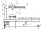
In order to solve the technical problem, the utility model provides an intelligent automatic feeding device of automotive brake to solve the intelligent automatic feeding device of current automotive brake and be not convenient for supplementary a large amount of materials of placing and place, be not convenient for auxiliary material carry and be not convenient for adjust and the problem that removes. An intelligent automatic feeding device of an automobile brake comprises a support, a workbench, a first speed reducer, a first rotating motor, a rotating tray, a PLC (programmable logic controller), a driving switch, a mounting seat, a ball screw pair, a second speed reducer, a second motor, an auxiliary column, a rodless cylinder, a finger cylinder, an auxiliary seat, an infrared sensor, a travel switch, an auxiliary discharging box structure, an adjustable conveying box structure, a movable lifting seat structure and a movable seat, wherein the workbench is welded at the upper end of the support; the first speed reducer bolt is arranged on the right side of the lower part of the workbench; the first rotating motor is arranged on the left side of the lower part of the first speed reducer through a bolt, and an output shaft is in key connection with the first speed reducer; the rotary tray is connected to the right side of the upper part of the first speed reducer through a key; the PLC bolt is arranged at the front part of the left side of the lower surface of the workbench, and a driving switch is embedded in the front surface; the mounting seat bolt is mounted on the left side of the upper surface of the workbench; the ball screw auxiliary shaft is connected in the mounting seat; the second speed reducer is installed at the upper end of the installation seat through a bolt, the lower part of the second speed reducer is connected with the ball screw pair key, and the left side of the second speed reducer is connected with an output shaft key of a second motor; the second motor bolt is arranged on the left side of the second speed reducer; the auxiliary column is welded in the middle of the upper surface of the workbench; the rodless cylinder bolt is arranged at the front part of the movable seat; the finger cylinder bolt is arranged on the inner side of the front part of the rodless cylinder; the auxiliary seat bolt is arranged on the outer side of the front part of the rodless cylinder; the infrared sensor bolt is arranged on the lower part of the front surface of the auxiliary seat; the travel switch bolt is arranged on the right side of the rodless cylinder; the auxiliary material placing box structure is arranged at the rear part of the workbench; the adjustable conveying box structure is arranged on the workbench; the movable lifting seat structure is arranged at the lower part of the bracket; the left side of the movable seat is connected with a ball screw pair through a bolt, and the right side of the movable seat is sleeved on an auxiliary column; the auxiliary material placing box structure comprises a storage box, an auxiliary block, a support rod, a communicating pipeline and an auxiliary pulley, wherein the support rod is welded around the lower surface of the storage box, and the front part of the support rod is welded with the left side of the rear part of the workbench; the communicating pipeline is welded at the lower part of the front surface of the storage box; the auxiliary pulleys are respectively installed on the left side and the right side of the inner wall of the communicating pipeline through bolts.
Preferably, the adjustable conveying box structure comprises a supporting box, supporting rods, a movable cavity, movable holes, fastening bolts and limiting plates, wherein the supporting rods are respectively welded on the periphery of the lower part of the supporting box and the middle left side of the upper surface of the workbench; the movable cavity is arranged on the upper side in the supporting box; the movable holes are respectively arranged at the left side and the right side in the supporting box, and the limiting plates are inserted in the movable holes; the fastening bolts are respectively in threaded connection with the left side and the right side of the front part of the supporting box.
Preferably, the movable lifting seat structure comprises a mounting edge, a fixing nut, a lifting screw, a rotating rod, a movable seat and a movable wheel, wherein the mounting edge is welded at the lower part of the outer wall of the bracket, and the fixing nut is welded in the mounting edge; the movable wheel is connected to the movable seat.
Preferably, the support rods arranged at the lower part of the storage box are supported, and the storage box is a stainless steel box.
Preferably, the auxiliary block is a triangular stainless steel block, and the auxiliary block is welded to the lower part of the inner wall of the storage box.
Preferably, the left side and the right side of the inner wall of the communicating pipeline are provided with auxiliary pulleys, the communicating pipeline is arranged to be inclined, one end of the communicating pipeline is communicated with the storage box, and the other end of the communicating pipeline is communicated with the movable cavity.
Preferably, the lower part of the supporting box is supported by a supporting rod, an internal movable cavity corresponds to the finger cylinder and the infrared sensor, and the supporting box is inclined.
Preferably, the two limiting plates are arranged on the left side and the right side of the inner part of the supporting box.
Preferably, the fastening bolt is in contact with the limiting plate in the movable hole.
Preferably, the moving seat and the moving wheel are respectively provided with a plurality of moving seats and moving wheels, and are arranged around the lower part of the outer wall of the support.
Preferably, the lifting screw is in threaded connection with the inside of the fixing nut; the rotary rod and the movable seat are respectively welded at the upper part and the lower part of the lifting screw rod.
Compared with the prior art, the beneficial effects of the utility model are that:
1. the utility model discloses in, the bracing piece of bin lower part be provided with a plurality ofly to support, the bin adopt the stainless steel case, be convenient for store a large amount of auto brake in the bin, and assist thereupon and carry appointed position department and carry.
2. The utility model discloses in, supplementary piece adopt triangle-shaped stainless steel piece, supplementary piece welding in the lower part of bin inner wall, when storing automobile brake, supplementary automobile brake carries and enters into the intercommunication pipeline and carries thereupon
3. The utility model discloses in, the left and right sides of intercommunication pipeline inner wall be provided with supplementary pulley, the intercommunication pipeline set up to the slope form, intercommunication pipeline one end and bin intercommunication, the other end and activity chamber intercommunication, when using, be convenient for assist single car stopper carry and enter into the activity intracavity and carry out the work of pressing from both sides the transport of getting.
4. The utility model discloses in, support box lower part support through branch and live, and inside activity chamber corresponds with finger cylinder and infrared ray sensor, the support box set up to the slope form, be convenient for supplementary automobile brake slides and reachs appointed position department, and supplementary clamp gets the work of carrying.
5. The utility model discloses in, the limiting plate be provided with two to the setting is in the inside left and right sides of support box, during the use, can restrict solitary automotive brake and carry, also can guarantee the straight line and slide when carrying simultaneously, thereby avoided making automotive brake appear inclining easily and be not convenient for press from both sides the problem of getting.
6. The utility model discloses in, fastening bolt and the downthehole limiting plate contact of activity, be convenient for make the limiting plate activity and adjust the interval between limiting plate and the limiting plate to be applicable to the work of the supplementary transport of not equidimension automobile brake.
7. The utility model discloses in, removal seat with remove the wheel and be provided with a plurality ofly respectively, and set up around the lower part of support outer wall, be convenient for remove and reach different position departments and use.
8. In the utility model, the lifting screw is connected in the fixed nut in a threaded manner; the rotary rod and the moving seat are respectively welded at the upper part and the lower part of the lifting screw rod, and can assist the moving wheel to lift, so that the moving wheel can be conveniently stored or used.
Drawings
Fig. 1 is a schematic structural diagram of the present invention.
Fig. 2 is a schematic structural diagram of the auxiliary discharge box structure of the present invention.
Fig. 3 is a schematic structural diagram of the structure of the adjustable conveying box of the present invention.
Fig. 4 is a schematic structural view of the movable lifting seat structure of the present invention.
Fig. 5 is a schematic diagram of the electrical connection of the present invention.
In the figure:
1. a support; 2. a work table; 3. a first decelerator; 4. a first rotating electrical machine; 5. rotating the tray; 6. a PLC; 7. a drive switch; 8. a mounting seat; 9. a ball screw pair; 10. a second decelerator; 11. a second motor; 12. an auxiliary column; 13. a rodless cylinder; 14. a finger cylinder; 15. an auxiliary seat; 16. an infrared sensor; 17. a travel switch; 18. an auxiliary material discharging box structure; 181. a storage tank; 182. an auxiliary block; 183. a support bar; 184. a communicating pipe; 185. an auxiliary pulley; 19. the structure of the adjustable conveying box; 191. a support box; 192. a strut; 193. a movable cavity; 194. a movable hole; 195. fastening a bolt; 196. a limiting plate; 20. a movable lifting seat structure; 201. installing edges; 202. fixing a nut; 203. a lifting screw; 204. rotating the rod; 205. a movable seat; 206. a moving wheel; 21. a movable seat.
Detailed Description
The invention is further described below with reference to the accompanying drawings:
example (b):
as shown in fig. 1 and fig. 2, an intelligent automatic feeding device for an automobile brake comprises a support 1, a workbench 2, a first speed reducer 3, a first rotating motor 4, a rotating tray 5, a PLC6, a driving switch 7, a mounting seat 8, a ball screw pair 9, a second speed reducer 10, a second motor 11, an auxiliary column 12, a rodless cylinder 13, a finger cylinder 14, an auxiliary seat 15, an infrared sensor 16, a travel switch 17, an auxiliary material placing box structure 18, an adjustable conveying box structure 19, a movable lifting seat structure 20 and a movable seat 21, wherein the workbench 2 is welded at the upper end of the support 1; the first speed reducer 3 is mounted on the right side of the lower part of the workbench 2 through bolts; the first rotating motor 4 is arranged on the left side of the lower part of the first speed reducer 3 through a bolt, and an output shaft is in key connection with the first speed reducer 3; the rotary tray 5 is connected to the right side of the upper part of the first speed reducer 3 in a key mode; the PLC6 bolt is arranged at the front part of the left side of the lower surface of the workbench 2, and a driving switch 7 is embedded in the front surface; the mounting seat 8 is mounted on the left side of the upper surface of the workbench 2 through a bolt; the ball screw pair 9 is coupled in the mounting seat 8; the second speed reducer 10 is mounted at the upper end of the mounting base 8 through a bolt, the lower part of the second speed reducer is in key connection with the ball screw pair 9, and the left side of the second speed reducer is in key connection with an output shaft of the second motor 11; the second motor 11 is mounted on the left side of the second speed reducer 10 through bolts; the auxiliary column 12 is welded in the middle of the upper surface of the workbench 2; the rodless cylinder 13 is mounted at the front part of the movable seat 21 through bolts; the finger cylinder 14 is mounted on the inner side of the front part of the rodless cylinder 13 through bolts; the auxiliary seat 15 is mounted on the outer side of the front part of the rodless cylinder 13 through bolts; the infrared sensor 16 is mounted on the lower part of the front surface of the auxiliary seat 15 through bolts; the travel switch 17 is mounted on the right side of the rodless cylinder 13 through a bolt; the auxiliary material discharge box structure 18 is arranged at the rear part of the workbench 2; the adjustable conveying box structure 19 is arranged on the workbench 2; the movable lifting seat structure 20 is arranged at the lower part of the bracket 1; the left side of the movable seat 21 is connected with the ball screw pair 9 through a bolt, and the right side of the movable seat is sleeved on the auxiliary column 12; the auxiliary discharging box structure 18 comprises a storage box 181, an auxiliary block 182, a support rod 183, a communication pipeline 184 and an auxiliary pulley 185, wherein the support rod 183 is welded around the lower surface of the storage box 181, and the front part of the support rod 183 is welded with the left side of the rear part of the workbench 2; the communication pipe 184 is welded at the lower part of the front surface of the storage tank 181; the auxiliary pulleys 185 are respectively bolted to the left and right sides of the inner wall of the communicating pipe 184.
In the above embodiment, as shown in fig. 3, specifically, the adjustable conveying box structure 19 includes a supporting box 191, a supporting rod 192, a movable cavity 193, a movable hole 194, a fastening bolt 195 and a limiting plate 196, wherein the supporting rod 192 is welded around the lower portion of the supporting box 191 and is welded on the middle left side of the upper surface of the working platform 2; the movable cavity 193 is arranged at the upper side inside the supporting box 191; the movable holes 194 are respectively formed in the left side and the right side of the interior of the supporting box 191, and limiting plates 196 are inserted into the movable holes 194; the fastening bolts 195 are respectively screwed at the left and right sides of the front portion of the support case 191.
As shown in fig. 4, in the above embodiment, specifically, the movable lifting seat structure 20 includes a mounting edge 201, a fixing nut 202, a lifting screw 203, a rotating rod 204, a moving seat 205 and a moving wheel 206, the mounting edge 201 is welded at the lower part of the outer wall of the bracket 1, and the fixing nut 202 is welded in the mounting edge 201; the moving wheel 206 is coupled to the moving base 205.
In the above embodiment, specifically, the plurality of support rods 183 are disposed at the lower portion of the storage tank 181 and support the storage tank 181, and the storage tank 181 is a stainless steel tank, so that a large number of automobile brakes can be stored in the storage tank 181 and then transported to a designated position in an auxiliary manner.
In the above embodiment, specifically, the auxiliary block 182 is a triangular stainless steel block, the auxiliary block 182 is welded to the lower portion of the inner wall of the storage tank 181, and the auxiliary block assists the automobile brake to be conveyed into the communication pipe 184 for conveying while storing the automobile brake
In the above embodiment, specifically, the auxiliary pulleys 185 are disposed on the left and right sides of the inner wall of the communication pipe 184, the communication pipe 184 is inclined, one end of the communication pipe 184 is communicated with the storage tank 181, and the other end of the communication pipe 184 is communicated with the movable cavity 193, so that when the clamping device is used, the auxiliary pulleys can assist the single automobile brake to convey and enter the movable cavity 193 to perform clamping and conveying operations.
In the above embodiment, specifically, the lower portion of the supporting box 191 is supported by the supporting rod 192, the inner movable cavity 193 corresponds to the finger cylinder 14 and the infrared sensor 16, and the supporting box 191 is inclined, so as to facilitate the sliding of the automobile brake to a specified position and the auxiliary gripping and conveying operation.
In the above embodiment, specifically, the two limiting plates 196 are disposed at the left and right sides inside the supporting box 191, so that when in use, a single automobile brake can be limited to be conveyed, and at the same time, the linear sliding can be ensured during the conveying, thereby avoiding the problem that the automobile brake is easy to incline and inconvenient to clamp.
In the above embodiment, specifically, the fastening bolt 195 is in contact with the limiting plate 196 in the movable hole 194, so that the limiting plate 196 can be moved, and the distance between the limiting plate 196 and the limiting plate 196 can be adjusted, thereby being suitable for the auxiliary conveying work of automobile brakes with different sizes.
In the above embodiment, specifically, the moving seat 205 and the moving wheel 206 are respectively provided in plural numbers, and are disposed around the lower portion of the outer wall of the support 1, so as to be convenient for moving and reaching different positions for use.
In the above embodiment, specifically, the lifting screw 203 is connected in the fixing nut 202 by a thread; the rotating rod 204 and the moving seat 205 are welded to the upper and lower portions of the lifting screw 203, respectively, and can be lifted and lowered in association with the auxiliary moving wheel 206, thereby facilitating storage of the moving wheel 206 or use of the moving wheel 206.
In the above embodiment, specifically, the first rotating electrical machine 4 is a model number 110BYG350D 20 N.M.
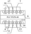
In the above embodiment, specifically, the PLC6 is a PLC of model FX 2N-48.
In the above embodiment, specifically, the second motor 11 is a motor of model ECMA-C30807 PS.
In the above embodiment, the rodless cylinder 13 is a type L-MY1M32G-400LS rodless cylinder.
In the above embodiment, specifically, the finger cylinder 14 is a HFZ type finger cylinder.
In the above embodiment, specifically, the infrared sensor 16 is a P923 type infrared sensor.
In the above embodiment, specifically, the travel switch 17 is a travel switch of model TQ-2519.
In the above embodiment, specifically, the driving switch 7 is electrically connected to an input terminal of the PLC6, the infrared sensor 16 is electrically connected to an input terminal of the PLC6, the stroke switch 17 is electrically connected to an input terminal of the PLC6, the first rotating electrical machine 4 is electrically connected to an output terminal of the PLC6, the second electrical machine 11 is electrically connected to an output terminal of the PLC6, the rodless cylinder 13 is electrically connected to an output terminal of the PLC6, and the finger cylinder 14 is electrically connected to an output terminal of the PLC 6.
Principle of operation
The utility model discloses a theory of operation: when the automobile brake is used, the automobile brake is placed in the storage tank 181, then enters the communication pipeline 184 through the auxiliary block 182, then enters the movable cavity 193 through the auxiliary pulley 185, and is positioned between the limiting plate 196 and the limiting plate 196, after the communication pipeline arrives, the second motor 11 and the rodless cylinder 13 are respectively started, so that the second motor 11 can drive the ball screw pair 9 to rotate through the second speed reducer 10, and then the movable seat 21 can be lifted up and down, meanwhile, the rodless cylinder 13 drives the finger cylinder 14 to move to a proper position, when the infrared sensor 16 detects the automobile brake, the finger cylinder 14 can be started to clamp the automobile brake, after clamping, the second motor 11 and the rodless cylinder 13 are started again, then the second motor 11 and the finger cylinder 14 are moved to a proper position above the rotary tray 5, then the finger cylinder 14 is driven, and the automobile brake is released, thus, the automobile brake can fall on the rotating tray 5, and the loading work is finished.
Utilize technical scheme, or technical personnel in the field are in the utility model discloses under technical scheme's the inspiration, design similar technical scheme, and reach above-mentioned technological effect, all fall into the utility model discloses a protection scope.