CN211725463U - Production agitating unit for health care composition - Google Patents
Production agitating unit for health care composition Download PDFInfo
- Publication number
- CN211725463U CN211725463U CN201922415993.XU CN201922415993U CN211725463U CN 211725463 U CN211725463 U CN 211725463U CN 201922415993 U CN201922415993 U CN 201922415993U CN 211725463 U CN211725463 U CN 211725463U
- Authority
- CN
- China
- Prior art keywords
- care composition
- stirring
- production
- health care
- block
- Prior art date
- Legal status (The legal status is an assumption and is not a legal conclusion. Google has not performed a legal analysis and makes no representation as to the accuracy of the status listed.)
- Active
Links
Images


Abstract
The utility model relates to the technical field of daily necessities product production equipment, and discloses a production agitating unit for health care composition, has solved the mixed agitated vessel of present daily necessities production and has been inconvenient to dismantle and wash the stirring facility after finishing using, and the mixed agitated vessel of simultaneous production is inside can remain and the problem of a large amount of health care composition products of adhesion when discharging health care composition products, and it includes the stirring mixing jar, the bottom fixedly connected with row material pipe of stirring mixing jar, the upper portion of row material pipe is installed the control valve, the equidistant fixedly connected with inlet pipe on stirring mixing jar upper portion, the top movable mounting of stirring mixing jar has the sealed lid; this agitating unit for producing health care composition can effectually dismantle and wash equipment after finishing using to effectual maintenance between equipment, this agitating unit for producing health care composition can clear up the inner wall of equipment at the in-process of arranging the material simultaneously, thereby very big reduction the problem of the residue and the adhesion of product.
Description
Technical Field
The utility model belongs to the technical field of daily product production facility, specifically be a production agitating unit for health care composition.
Background
Since consumers today can pick a large variety of home and personal care products, manufacturers need to clearly show how unique their brands are. Specialized products that contain novel fragrances and active ingredients in multi-colored compositions presented in transparent and translucent packaging are now quite common.
The current body care composition production mixing and stirring equipment is inconvenient to disassemble and clean the stirring facilities after use, and simultaneously, the production mixing and stirring equipment can remain and adhere a large amount of body care composition products inside when the body care composition is discharged; therefore, improvements are now needed in view of the current situation.
Disclosure of Invention
To the above-mentioned condition, for overcoming prior art's defect, the utility model provides a production agitating unit for health care composition, the effectual mixed agitated vessel of present health care composition production of having solved is not convenient for dismantle and wash stirring facility after finishing using, and the mixed agitated vessel of coproduction is inside can remain and the problem of the a large amount of health care compositions of adhesion when discharge health care composition.
In order to achieve the above object, the utility model provides a following technical scheme: the utility model provides a production health care agitating unit for composition, mix the jar including the stirring, the bottom fixedly connected with who stirs the mixed jar arranges the material pipe, arrange the upper portion of material pipe and install the control valve, the equidistance fixedly connected with inlet pipe on stirring mixed jar upper portion, the top movable mounting who stirs the mixed jar has sealed lid, the top fixed mounting of sealed lid has the motor, cross recess has been seted up at the middle part of sealed lid bottom, the inside movable mounting of cross recess has the pivot, the (mixing) shaft is installed to the surface symmetry of pivot, and the fixed surface of pivot installs the spiral scraper blade, fixed establishment is all installed to the both sides at cross recess middle part and the inside.
Preferably, the top of the rotating shaft is fixedly provided with a round block, the middle of the round block is provided with a round groove, and the top of the round block is provided with a quadrilateral groove.
Preferably, the output end of the motor is fixedly connected with a quadrilateral clamping block in the cross groove, and the quadrilateral clamping block is movably clamped in the quadrilateral groove.
Preferably, lifting lugs are fixedly mounted on two sides of the top of the sealing cover.
Preferably, two fixed establishment all includes screw hole, threaded shaft, semicircle fixed block and carousel, and two screw holes are seted up in the both sides at sealed lid middle part, and the one end of two screw holes is linked together with the both sides at cross recess middle part respectively, and threaded shaft threaded connection is in the inside of screw hole, and the one end of threaded shaft extends to the inside of cross recess and is connected with semicircle fixed block activity, and semicircle fixed block activity joint is in the inside of circle recess, and the other end of threaded shaft extends to outside the one side of sealed lid and is connected with the carousel stationary phase.
Preferably, one end of the threaded shaft is connected with the semicircular fixing block through a bearing, and the top and the bottom of the semicircular fixing block are movably clamped with balls at equal distances.
Compared with the prior art, the beneficial effects of the utility model are that:
(1) during work, the stirring device for producing the body care composition can effectively disassemble and clean equipment after being used by being provided with the quadrilateral clamping block, the cross groove, the rotating shaft, the round block, the round groove, the quadrilateral groove, the fixing mechanism, the threaded hole, the threaded shaft, the semicircular fixing block and the turntable, so that the equipment room can be effectively maintained; firstly, the sealing cover is lifted by external hoisting equipment and a lifting lug to separate the sealing cover from the stirring and mixing cylinder, then the threaded shaft drives the semicircular fixing block to move out of the circular groove by rotating the turntable, then the rotating shaft is moved out of the cross groove, and the quadrilateral fixing block is moved out of the quadrilateral groove, so that the rotating shaft, the stirring shaft, the spiral scraper and the stirring and mixing cylinder are cleaned and maintained conveniently;
(2) the spiral scraper is arranged, so that the inner wall of the equipment can be cleaned in the discharging process of the stirring device for producing the body care composition, and the problems of product residue and adhesion are greatly reduced; make it drive the pivot and rotate when starter motor, the rotation of pivot can drive the (mixing) shaft and rotate the stirring, and the rotation of pivot can drive the spiral scraper blade simultaneously and rotate, makes the spiral scraper blade scrape the product of remaining and adhesion on stirring mixing cylinder inner wall and get.
Drawings
The accompanying drawings are included to provide a further understanding of the invention, and are incorporated in and constitute a part of this specification, illustrate embodiments of the invention, and together with the description serve to explain the invention and not to limit the invention.
In the drawings:
FIG. 1 is a schematic structural view of the present invention;
fig. 2 is a schematic sectional view of the sealing cover of the present invention;
FIG. 3 is a schematic diagram of a portion of the structure of FIG. 2 according to the present invention;
FIG. 4 is a schematic view of a partial cross-sectional structure of the rotating shaft of the present invention;
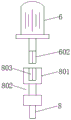
in the figure: 1. a stirring and mixing cylinder; 2. a discharge pipe; 3. a control valve; 4. a feed pipe; 5. a sealing cover; 6. a motor; 601. lifting lugs; 602. a quadrilateral fixture block; 7. a cross groove; 8. a rotating shaft; 801. a round block; 802. a circular groove; 803. a quadrilateral groove; 9. a stirring shaft; 10. a spiral scraper; 11. a fixing mechanism; 1101. a threaded hole; 1102. a threaded shaft; 1103. a semicircular fixed block; 1104. a turntable.
Detailed Description
The technical solutions in the embodiments of the present invention will be clearly and completely described below with reference to the drawings in the embodiments of the present invention, and it is obvious that the described embodiments are only some embodiments of the present invention, not all embodiments; based on the embodiments in the present invention, all other embodiments obtained by a person skilled in the art without creative work belong to the protection scope of the present invention.
In the first embodiment, as shown in fig. 1, 2, 3 and 4, the present invention comprises a stirring and mixing tank 1, a material discharging pipe 2 is fixedly connected to the bottom of the stirring and mixing tank 1, a control valve 3 is installed on the upper portion of the material discharging pipe 2, a material feeding pipe 4 is fixedly connected to the upper portion of the stirring and mixing tank 1 at equal intervals, a sealing cover 5 is movably installed on the top of the stirring and mixing tank 1, a motor 6 is fixedly installed on the top of the sealing cover 5, a cross groove 7 is opened in the middle of the bottom of the sealing cover 5, the rotating shaft 8 can be effectively installed through the arrangement of the cross groove 7, the rotating shaft 8 is movably installed in the cross groove 7, the stirring shafts 9 are symmetrically installed on the surface of the rotating shaft 8, the spiral scraping plate 10 is fixedly installed on the surface of the rotating shaft 8, through the setting of spiral scraper blade 10, can effectually scrape the clearance of getting to the inner wall of stirring mixing cylinder 1, fixed establishment 11 is all installed to the both sides at cross recess 7 middle part and the both sides that are located sealed lid 5 inside.
In the second embodiment, based on the first embodiment, as shown in fig. 4, a round block 801 is fixedly mounted at the top of the rotating shaft 8, a round groove 802 is formed in the middle of the round block 801, a quadrilateral groove 803 is formed in the top of the round block 801, and the rotating shaft 8 can be effectively mounted and dismounted by the arrangement of the round block 801, the round groove 802 and the quadrilateral groove 803.
In the third embodiment, based on the first embodiment, as shown in fig. 4, a quadrilateral clamping block 602 is fixedly connected to the output end of the motor 6 and located inside the cross slot 7, the quadrilateral clamping block 602 is movably clamped inside the quadrilateral groove 803, and the motor 6 can effectively drive the rotating shaft 8 to rotate through the arrangement of the quadrilateral clamping block 602.
In the fourth embodiment, on the basis of the first embodiment, as shown in fig. 3, lifting lugs 601 are fixedly mounted on both sides of the top of the sealing cover 5, and the sealing cover 5 can be effectively lifted, mounted and dismounted by the aid of the lifting lugs 601.
Fifth embodiment, on the basis of the first embodiment, as shown in fig. 3 and 4, each of the two fixing mechanisms 11 includes a threaded hole 1101, a threaded shaft 1102, a semicircular fixing block 1103 and a rotary plate 1104, the two threaded holes 1101 are disposed on two sides of the middle portion of the sealing cover 5, one ends of the two threaded holes 1101 are respectively communicated with two sides of the middle portion of the cross groove 7, the threaded shaft 1102 is in threaded connection inside the threaded hole 1101, one end of the threaded shaft 1102 extends into the cross groove 7 and is movably connected with the semicircular fixing block 1103, the semicircular fixing block 1103 is movably clamped inside the circular groove 802, the other end of the threaded shaft 1102 extends out of one side of the sealing cover 5 and is fixedly connected with the rotary plate 1104, and the threaded hole 1101, the threaded shaft 1102, the semicircular fixing block 1103 and the rotary plate 1104 are arranged to enable the threaded shaft 8 to be stably and effectively fixed.
Sixth embodiment, on fifth embodiment's basis, given by fig. 3, be connected through the bearing between the one end of screw shaft 1102 and the semicircle fixed block 1103, the equal distance activity joint in top and the bottom of semicircle fixed block 1103 has the ball to pass through the setting of ball to make pivot 8 can effectually rotate.
In this embodiment: the motor 6 adopts a slow motor of 6M200GU-C type.
The working principle is as follows: when the motor 6 is started to drive the rotating shaft 8 to rotate, the rotating shaft 8 can drive the stirring shaft 9 to rotate and stir, and meanwhile, the rotating shaft 8 can drive the spiral scraper 10 to rotate, so that the spiral scraper 10 scrapes the products remained and adhered to the inner wall of the stirring and mixing cylinder 1; firstly, the sealing cover 5 is lifted by external hoisting equipment and the lifting lug 601, so that the sealing cover 5 is separated from the stirring and mixing cylinder 1, then the threaded shaft 1102 drives the semicircular fixing block 1103 to move out of the circular groove 802 by rotating the rotary table 1104, then the rotating shaft 8 is moved out of the cross groove 7, and the quadrangular clamping block 602 is moved out of the quadrangular groove 803, so that the rotating shaft 8, the stirring shaft 9, the spiral scraper 10 and the inside of the stirring and mixing cylinder 1 can be cleaned and maintained conveniently.
It is noted that, herein, relational terms such as first and second, and the like may be used solely to distinguish one entity or action from another entity or action without necessarily requiring or implying any actual such relationship or order between such entities or actions. Also, the terms "comprises," "comprising," or any other variation thereof, are intended to cover a non-exclusive inclusion, such that a process, method, article, or apparatus that comprises a list of elements does not include only those elements but may include other elements not expressly listed or inherent to such process, method, article, or apparatus.
Although embodiments of the present invention have been shown and described, it will be appreciated by those skilled in the art that changes, modifications, substitutions and alterations can be made in these embodiments without departing from the principles and spirit of the invention, the scope of which is defined in the appended claims and their equivalents.
Claims (6)
1. A stirring device for producing a body-care composition, comprising a stirring and mixing tank (1), characterized in that: the utility model discloses a stirring mixing tank, including stirring mixing tank (1), the bottom fixedly connected with of stirring mixing tank (1) arranges material pipe (2), control valve (3) are installed on the upper portion of arranging material pipe (2), equidistance fixedly connected with inlet pipe (4) on stirring mixing tank (1) upper portion, the top movable mounting of stirring mixing tank (1) has sealed lid (5), the top fixed mounting of sealed lid (5) has motor (6), cross recess (7) have been seted up at the middle part of sealed lid (5) bottom, the inside movable mounting of cross recess (7) has pivot (8), (mixing) shaft (9) are installed to the surface symmetry of pivot (8), and the fixed surface of pivot (8) installs spiral scraper blade (10), fixed establishment (11) are all installed to the both sides at cross recess (7) middle part and.
2. The stirring device for the production of a body care composition according to claim 1, wherein: the top of the rotating shaft (8) is fixedly provided with a round block (801), the middle of the round block (801) is provided with a round groove (802), and the top of the round block (801) is provided with a quadrilateral groove (803).
3. The stirring device for the production of a body care composition according to claim 1, wherein: the output end of the motor (6) is positioned in the cross groove (7), a quadrilateral clamping block (602) is fixedly connected inside the cross groove, and the quadrilateral clamping block (602) is movably clamped inside the quadrilateral groove (803).
4. The stirring device for the production of a body care composition according to claim 1, wherein: lifting lugs (601) are fixedly mounted on two sides of the top of the sealing cover (5).
5. The stirring device for the production of a body care composition according to claim 1, wherein: two fixed establishment (11) all include screw hole (1101), threaded shaft (1102), semicircle fixed block (1103) and carousel (1104), two both sides at sealed lid (5) middle part are seted up in screw hole (1101), and the one end of two screw holes (1101) is linked together with the both sides at cross recess (7) middle part respectively, threaded shaft (1102) threaded connection is in the inside of screw hole (1101), and the one end of threaded shaft (1102) extends to the inside of cross recess (7) and is connected with semicircle fixed block (1103) activity, semicircle fixed block (1103) activity joint is in the inside of circular recess (802), the other end of threaded shaft (1102) extends to outside one side of sealed lid (5) and is connected with carousel (1104) is fixed.
6. The stirring device for the production of a body care composition according to claim 5, wherein: one end of the threaded shaft (1102) is connected with the semicircular fixing block (1103) through a bearing, and balls are movably clamped at equal distances between the top and the bottom of the semicircular fixing block (1103).
Priority Applications (1)
| Application Number | Priority Date | Filing Date | Title |
|---|---|---|---|
| CN201922415993.XU CN211725463U (en) | 2019-12-27 | 2019-12-27 | Production agitating unit for health care composition |
Applications Claiming Priority (1)
| Application Number | Priority Date | Filing Date | Title |
|---|---|---|---|
| CN201922415993.XU CN211725463U (en) | 2019-12-27 | 2019-12-27 | Production agitating unit for health care composition |
Publications (1)
| Publication Number | Publication Date |
|---|---|
| CN211725463U true CN211725463U (en) | 2020-10-23 |
Family
ID=72871484
Family Applications (1)
| Application Number | Title | Priority Date | Filing Date |
|---|---|---|---|
| CN201922415993.XU Active CN211725463U (en) | 2019-12-27 | 2019-12-27 | Production agitating unit for health care composition |
Country Status (1)
| Country | Link |
|---|---|
| CN (1) | CN211725463U (en) |
Cited By (1)
| Publication number | Priority date | Publication date | Assignee | Title |
|---|---|---|---|---|
| CN112847885A (en) * | 2021-02-08 | 2021-05-28 | 陈肇超 | Plastic polymer melting device |
-
2019
- 2019-12-27 CN CN201922415993.XU patent/CN211725463U/en active Active
Cited By (1)
| Publication number | Priority date | Publication date | Assignee | Title |
|---|---|---|---|---|
| CN112847885A (en) * | 2021-02-08 | 2021-05-28 | 陈肇超 | Plastic polymer melting device |
Similar Documents
| Publication | Publication Date | Title |
|---|---|---|
| CN205392242U (en) | Take scraper and belt cleaning device's chemical industry agitator tank | |
| CN209810133U (en) | Novel silica gel production device | |
| CN214051255U (en) | Stirring processing equipment for high-viscosity materials | |
| CN106422891A (en) | High mixing power blending device capable of separately adding solid and liquid | |
| CN115400637B (en) | Integrated intelligent medicine dispensing system for pharmacy | |
| CN211725463U (en) | Production agitating unit for health care composition | |
| CN209810045U (en) | Liquid medicine churn that facilitates use | |
| CN207722663U (en) | A kind of industrial blender stirred evenly | |
| CN211389643U (en) | Polyethylene raw material stirring device | |
| CN209564979U (en) | A kind of reaction kettle stirring cleaning plant with regulatory function | |
| CN218928201U (en) | Low-speed stirring device convenient to clean | |
| CN208493862U (en) | A kind of Cosmetic Manufacture industrial chemicals agitating device | |
| CN217962130U (en) | Mixing and stirring mechanism for raw materials for producing butyl daub | |
| CN216499358U (en) | Reation kettle is used in catalyst production | |
| CN216171927U (en) | Blending kettle with shearing mechanism at bottom | |
| CN213913409U (en) | Chemical industry coating production is with mixing of colors cauldron of row of being convenient for material | |
| CN111888983A (en) | Mixed liquid stirring device for chemical production | |
| CN209155669U (en) | A kind of mechanical engineering agitating device | |
| CN212632480U (en) | Chemical raw material stirring device | |
| CN207576258U (en) | A kind of large size blender | |
| CN207951250U (en) | A kind of burden agitator stirred evenly | |
| CN215312280U (en) | Reaction kettle capable of being automatically cleaned for biochemical pharmacy | |
| CN217367985U (en) | Multifunctional liquid preparation barrel | |
| CN219897861U (en) | Grinding apparatus raw materials compounding device | |
| CN218834362U (en) | Mechanism charcoal agitating unit |
Legal Events
| Date | Code | Title | Description |
|---|---|---|---|
| GR01 | Patent grant | ||
| GR01 | Patent grant | ||
| TR01 | Transfer of patent right | ||
| TR01 | Transfer of patent right |
Effective date of registration: 20220401 Address after: 215000 No. 198 Anyang Road, Hushuguan Town, Suzhou high tech Zone, Suzhou, Jiangsu Patentee after: SUZHOU GREENLEAF DAILY COMMODITY Co.,Ltd. Address before: Room 102, building 5, 88 Darwin Road, China (Shanghai) pilot Free Trade Zone, Pudong New Area, Shanghai, 200120 Patentee before: SHANGHAI LVRUI BIOTECHNOLOGY Co.,Ltd. |