CN211702772U - Network rack with it is waterproof to remove dust - Google Patents
Network rack with it is waterproof to remove dust Download PDFInfo
- Publication number
- CN211702772U CN211702772U CN201921728448.XU CN201921728448U CN211702772U CN 211702772 U CN211702772 U CN 211702772U CN 201921728448 U CN201921728448 U CN 201921728448U CN 211702772 U CN211702772 U CN 211702772U
- Authority
- CN
- China
- Prior art keywords
- box
- top surface
- box body
- dust
- chassis
- Prior art date
- Legal status (The legal status is an assumption and is not a legal conclusion. Google has not performed a legal analysis and makes no representation as to the accuracy of the status listed.)
- Expired - Fee Related
Links
Images


Abstract
The utility model discloses a network cabinet with dust removal and water prevention, which comprises a box body, wherein the top surface of the box body is provided with a rain-proof component, the two side surfaces of the box body are provided with radiating holes, the inner end of each radiating hole is provided with a fan, the outer end of the radiating hole is provided with a dust-proof component, the front end surface of the box body is provided with a box door, a chassis is arranged below the box body, the middle part of the top surface of the chassis is provided with a shock-absorbing component, the two ends of; the cavity is established to box inside, and two baffles are established at the cavity middle part, and every baffle surface evenly distributes the small opening, and power, treater, temperature sensor are established to the top baffle top surface of the top, and the storing box is established to the cavity lower extreme, and the swash plate is all established to storing box both sides, and every swash plate one end is all established in storing box top, and first bracing piece is all established to every swash plate bottom surface. The utility model discloses a louvre outer end all establishes the dustproof subassembly, blocks the dust to be equipped with the influence that rain-proof subassembly protection box avoided sleet weather, inside storing box, the swash plate of being equipped with of box reduces the inside electrical components of box and breaks down.
Description
Technical Field
The utility model relates to a network rack field with it is waterproof to remove dust especially relates to a network rack with it is waterproof to remove dust.
Background
The network cabinet is an electrical device in the operation process of an electric power system and is used for combining and installing panels, plug-in units, plug-in boxes, electronic elements, devices, mechanical parts and components to form an integral installation box. As shown in the chinese patent No. 201721463072.5, the heat dissipation method of the conventional network cabinet mainly uses heat dissipation holes to dissipate heat, which has poor heat dissipation effect, is difficult to achieve the purpose of efficient heat dissipation, and cannot prevent dust and water, thereby easily causing damage to electrical components inside the cabinet.
SUMMERY OF THE UTILITY MODEL
The utility model aims at solving the defects existing in the prior art and providing a network cabinet with dust removal and water prevention functions.
In order to achieve the above purpose, the utility model adopts the following technical scheme: a network cabinet with dust removal and water prevention functions comprises a box body, wherein a rain-proof component is arranged on the top surface of the box body, two heat dissipation holes are formed in two side surfaces of the box body, a fan is arranged at the inner end of each heat dissipation hole, a dust-proof component is arranged at the outer end of each heat dissipation hole, a box door is arranged on the front end surface of the box body, the box door is hinged to the front end surface of the box body, a first handle is arranged on the surface of the box door, a chassis is arranged below the box body, a plurality of shock absorption components are arranged in the middle of the top surface of the chassis, the top surface of each shock absorption component is in contact with the bottom surface of the box body, the bottom surface of each shock absorption component is in contact with the top surface of the chassis, a connecting;
the inside of box is equipped with the cavity, the middle part of cavity is equipped with two horizontal baffles that set up, every the surface of baffle distributes all has a plurality of small opening, the top surface of baffle is equipped with power, treater, the equal rigid coupling in bottom surface of power, treater is in the top surface of baffle, the top surface of power is equipped with temperature sensor, the lower extreme of cavity is equipped with the storing box, the outer terminal surface of storing box is equipped with the second handle, the both sides of storing box all are equipped with the swash plate, every the one end of swash plate all sets up the top at the storing box, every the bottom surface of swash plate all is equipped with the first bracing piece of vertical setting, treater, fan all with power electric connection, the output of treater and the input electric connection of fan.
Preferably, the rainproof assembly comprises a second support rod, a third support rod, a support block, a connecting block and a rainproof plate, the second support rod is longitudinally arranged in the middle of the top surface of the box body, the third support rods are longitudinally arranged at two end parts of the top surface of the box body, the support block is fixedly connected to the top ends of the second support rods, the connecting block is fixedly connected to the top ends of the support blocks, one end of the rainproof plate is fixedly connected to two ends of the connecting block, and the middle part of the rainproof plate is connected to the top ends of the third support rods;
preferably, the dustproof assembly comprises a dustproof box, clamping plates, a dustproof cover, clamping blocks, a second connecting plate and a connecting pipe, the dustproof box is longitudinally arranged at the outer ends of the radiating holes, the dustproof cover is arranged on one side face of the dustproof box, a mounting groove is formed in the other side face of the dustproof box, the clamping plates are arranged at the top end and the bottom end of the mounting groove, a clamping groove is formed between each clamping plate and the inner end of the mounting groove, a through hole is formed between the two side faces of the dustproof box, one end of the connecting pipe is connected with the outer end of the radiating holes, the second connecting plate which is transversely arranged is arranged at the upper portion and the lower portion of the other end of the connecting pipe, one side of each second connecting;
preferably, the cushioning component comprises an upper baffle, a spring and a lower baffle, wherein the top surface of the upper baffle is contacted with the bottom surface of the box body, the bottom surface of the upper baffle is fixedly connected with the top end of the spring, the bottom end of the spring is fixedly connected with the top surface of the lower baffle, and the bottom surface of the lower baffle is contacted with the top surface of the chassis;
preferably, the connecting assembly comprises a connecting plate, a bolt and a columnar protrusion, the bottom surface of one end of the connecting plate is provided with the columnar protrusion, the top surface of one end of the connecting plate is provided with a threaded hole, the bolt is arranged inside the threaded hole, the columnar protrusion is clamped with the clamping groove, and the connecting plate is fixed with the chassis through the bolt;
preferably, the bottom feet are L-shaped plates with acute longitudinal section angles; the storage box is a box body with an open top surface.
Compared with the prior art, the beneficial effects of the utility model are that:
1. the utility model adopts the structure that the outer end of each heat dissipation hole is provided with the dustproof component, when the fan in the heat dissipation hole sucks external air into the box body, the dustproof component blocks the dust, and the dust is periodically taken down and cleaned, so that the dust can be conveniently and quickly replaced and maintained;
2. the utility model adopts the rain-proof component to protect the box body from the influence of rain and snow weather, and the storage box and the inclined plate are arranged in the box body to collect the water cooled down by the wet gas in the box body, thereby reducing the condition that the electrical elements in the box body are in failure;
to sum up, the utility model discloses a louvre outer end all establishes the dustproof subassembly, blocks the dust to be equipped with the influence that rain-proof subassembly protection box avoided sleet weather, inside storing box, the swash plate of being equipped with of box reduces the inside electrical components of box and breaks down.
Drawings
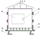
Fig. 1 is a schematic view of the overall structure proposed by the present invention;
fig. 2 is an overall front view of the present invention;
fig. 3 is a schematic diagram of the region a according to the present invention;
fig. 4 is a schematic diagram of a region B provided by the present invention;
number in the figure: the box body 1, the fan 2, the second support rod 3, the third support rod 4, the rain baffle 5, the support block 6, the power supply 7, the processor 8, the partition plate 9, the inclined plate 10, the first support rod 11, the storage box 12, the second handle 13, the bolt 14, the connecting plate 15, the chassis 16, the footing 17, the box door 18, the first handle 19, the connecting pipe 20, the second connecting plate 21, the fixture block 22, the clamping plate 23, the dust cover 24, the dust-proof box 25, the upper baffle 26, the spring 27 and the lower baffle 28.
Detailed Description
The technical solutions in the embodiments of the present invention will be described clearly and completely with reference to the accompanying drawings in the embodiments of the present invention, and it is obvious that the described embodiments are only some embodiments of the present invention, not all embodiments.
Referring to fig. 1-4, a dust-removing and water-proof network cabinet comprises a cabinet 1, wherein a rain-proof component is disposed on the top surface of the cabinet 1, the cabinet is protected from wind and snow by the rain-proof component, two heat dissipation holes are disposed on both side surfaces of the cabinet 1, a fan 2 is disposed at the inner end of each heat dissipation hole, a dust-proof component is disposed at the outer end of each heat dissipation hole, dust entering the cabinet 1 is blocked by the cooperation of the fan 2 and the dust-proof component, a cabinet door 18 is disposed on the front end surface of the cabinet 1, the cabinet door 18 is hinged to the front end surface of the cabinet 1, a first handle 19 is disposed on the surface of the cabinet door 18, a chassis 16 is disposed below the cabinet 1, a plurality of shock-absorbing components are disposed in the middle of the top surface of the chassis 16, and the cabinet 1 reduces the influence of external environment on the, the top surface of each shock absorption component is in contact with the bottom surface of the box body 1, the bottom surface of each shock absorption component is in contact with the top surface of the chassis 16, the two ends of the top surface of the chassis 16 are respectively provided with a connecting component and a clamping groove, and four corners of the bottom surface of the chassis 16 are respectively provided with a bottom foot 17;
a cavity is arranged in the box body 1, two transverse partition plates 9 are arranged in the middle of the cavity, a plurality of leakage holes are distributed on the surface of each partition plate 9, water cooled by moisture in the box body 1 falls off through a leak and then falls into the storage box 12, a power supply 7 and a processor 8 are arranged on the top surface of the uppermost partition plate 9, a temperature sensor is arranged on the top surface of the power supply 7, and the information output end of the temperature sensor is electrically connected with the input end of the processor 8; the equal rigid coupling in bottom surface of power 7, treater 8 is in the top surface of baffle 9, the lower extreme of cavity is equipped with storing box 12, the outer terminal surface of storing box 12 is equipped with second handle 13, the both sides of storing box 12 all are equipped with swash plate 10, every the one end of swash plate 10 all sets up in the top of storing box 12, every the bottom surface of swash plate 10 all is equipped with the first bracing piece 11 of vertical setting, treater 8, fan 2 all with power 7 electric connection, the output of treater 8 and the input electric connection of fan 2.
The utility model discloses in, rain-proof subassembly includes second bracing piece 3, third bracing piece 4, supporting shoe 6, connecting block, weather shield 5, the top surface middle part of box 1 is equipped with the second bracing piece 3 of vertical setting, and the top surface both ends of box 1 all are equipped with the third bracing piece 4 of vertical setting, the top rigid coupling of second bracing piece 3 has supporting shoe 6, the top rigid coupling of supporting shoe 6 has the connecting block, the equal rigid coupling in both ends of connecting block has the one end of weather shield 5, the top of third bracing piece 4 is connected at the middle part of weather shield 5.
In the utility model, the dustproof component comprises a dustproof box 25, a clamping plate 23, a dustproof cover 24, a clamping block 22, a second connecting plate 21 and a connecting pipe 20, the dustproof box 25 is longitudinally arranged at the outer end of the heat dissipation hole, one side surface of the dustproof box 25 is provided with the dustproof cover 24, the other side surface of the dustproof box 25 is provided with a mounting groove, the top end and the bottom end of the mounting groove are both provided with the clamping plate 23, each clamping plate 23 and the inner end of the mounting groove form a clamping groove, a through hole is arranged between the two side surfaces of the dustproof box 25, one end of the connecting pipe 20 is connected with the outer end of the heat dissipation hole, the upper part and the lower part of the other end of the connecting pipe 20 are both provided with the second connecting plate 21 which are transversely arranged, one side of each second connecting plate 21 is provided with the clamping block 22, the clamping block 22 is clamped with the clamping groove, the dustproof component is, thereby removing the dust-proof assembly for maintenance.
The utility model discloses in, the bradyseism subassembly includes overhead gage 26, spring 27, lower baffle 28, the bottom surface of overhead gage 26's top surface contact box 1, the top of overhead gage 26's bottom surface rigid coupling spring 27, the top surface of baffle 28 under spring 27's bottom rigid coupling, the top surface on lower baffle 28's bottom surface contact chassis 16 protects box 1 through the bradyseism subassembly, avoids external factors to influence the inside electrical components of box 1.
The utility model discloses in, coupling assembling includes that connecting plate 15, bolt 14, column are protruding, the one end bottom surface of connecting plate 15 is equipped with the column and protrudingly, and the one end top surface of connecting plate 15 is equipped with the screw hole, the inside of screw hole is equipped with bolt 14, the column is protruding and screens groove block, and connecting plate 15 is fixed with chassis 16 through bolt 14.
In the utility model, the footing 17 is an L-shaped plate with an acute longitudinal section angle, and the footing 17 can play a role of cushioning; the storage box 12 is a box body with an open top surface, and water in the storage box 12 is convenient to collect and dump.
The working principle is as follows: open switch, the treater is equipped with the threshold value, and temperature sensor detects temperature data, with temperature data transmission to the treater, when temperature data reached the threshold value, the fan rotation instruction was assigned to the treater, and the fan will begin to rotate and dispel the heat to the box inside, and the rain-proof subassembly of top surface of box plays the effect that prevents that sleet from getting into the box to the box, and the bradyseism subassembly of box bottom surface plays the guard action to the box, the connecting plate carries on spacingly with the bolt to the box, prevents that the box from sliding, the footing plays certain bradyseism effect, and after the inside temperature of box reduces, the moisture cooling is water, drops through the leak, then falls into the storing box, opens the chamber door again and takes out and fall.
The above, only be the concrete implementation of the preferred embodiment of the present invention, but the protection scope of the present invention is not limited thereto, and any person skilled in the art is in the technical scope of the present invention, according to the technical solution of the present invention and the utility model, the concept of which is equivalent to replace or change, should be covered within the protection scope of the present invention.
Claims (7)
1. The utility model provides a network rack with it is waterproof to remove dust, includes box (1), its characterized in that: the top surface of the box body (1) is provided with a rainproof assembly, two heat dissipation holes are respectively arranged on the two side surfaces of the box body (1), the inner end of each heat dissipation hole is provided with a fan (2), the outer end of each heat dissipation hole is provided with a dustproof assembly, a box door (18) is arranged on the front end surface of the box body (1), the box door (18) is hinged with the front end surface of the box body (1), a first handle (19) is arranged on the surface of the box door (18), a chassis (16) is arranged below the box body (1), a plurality of shock absorption components are arranged in the middle of the top surface of the chassis (16), the top surface of each shock absorption component is contacted with the bottom surface of the box body (1), the bottom surface of each shock absorption component is contacted with the top surface of the chassis (16), the two ends of the top surface of the chassis (16) are respectively provided with a connecting component and a clamping groove, and four corners of the bottom surface of the chassis (16) are respectively provided with a bottom foot (17);
the inside of box (1) is equipped with the cavity, the middle part of cavity is equipped with baffle (9) of two horizontal settings, every the surface of baffle (9) all distributes and has a plurality of small opening, the top surface of baffle (9) is equipped with power (7), treater (8), the equal rigid coupling in bottom surface of power (7), treater (8) is in the top surface of baffle (9), the top surface of power (7) is equipped with temperature sensor, the lower extreme of cavity is equipped with storing box (12), the outer terminal surface of storing box (12) is equipped with second handle (13), the both sides of storing box (12) all are equipped with swash plate (10), every the one end of swash plate (10) all sets up in the top of storing box (12), every the bottom surface of swash plate (10) all is equipped with first bracing piece (11) of vertical setting, treater (8), The fan (2) is electrically connected with the power supply (7), and the output end of the processor (8) is electrically connected with the input end of the fan (2).
2. The network cabinet with dust removal and water prevention functions as claimed in claim 1, wherein: the rain-proof subassembly includes second bracing piece (3), third bracing piece (4), supporting shoe (6), connecting block, weather shield (5), the top surface middle part of box (1) is equipped with second bracing piece (3) of vertical setting, and the top surface both ends of box (1) all are equipped with third bracing piece (4) of vertical setting, the top rigid coupling of second bracing piece (3) has supporting shoe (6), the top rigid coupling of supporting shoe (6) has the connecting block, the equal rigid coupling in both ends of connecting block has the one end of weather shield (5), the top of third bracing piece (4) is connected at the middle part of weather shield (5).
3. The network cabinet with dust removal and water prevention functions as claimed in claim 1, wherein: the dustproof assembly comprises a dustproof box (25), a clamping plate (23), a dustproof cover (24), a clamping block (22), a second connecting plate (21) and a connecting pipe (20), the dust-proof box (25) is longitudinally arranged at the outer end of the heat dissipation hole, a dust cover (24) is arranged on one side surface of the dust-proof box (25), an installation groove is arranged on the other side surface of the dust-proof box (25), clamping plates (23) are arranged at the top end and the bottom end of the mounting groove, each clamping plate (23) and the inner end of the mounting groove form a clamping groove, the dustproof box is characterized in that a through hole is formed between two side faces of the dustproof box (25), one end of the connecting pipe (20) is connected with the outer end of the heat dissipation hole, the upper portion and the lower portion of the other end of the connecting pipe (20) are respectively provided with a second connecting plate (21) which is transversely arranged, one side of each second connecting plate (21) is provided with a clamping block (22), and each clamping block (22) is clamped with the clamping groove.
4. The network cabinet with dust removal and water prevention functions as claimed in claim 1, wherein: the bradyseism subassembly includes overhead gage (26), spring (27), lower baffle (28), the bottom surface of the top surface contact box (1) of overhead gage (26), the top of the bottom surface rigid coupling spring (27) of overhead gage (26), the top surface of baffle (28) under the bottom rigid coupling of spring (27), the top surface of the bottom surface contact chassis (16) of baffle (28) down.
5. The network cabinet with dust removal and water prevention functions as claimed in claim 1, wherein: coupling assembling includes that connecting plate (15), bolt (14), column are protruding, the one end bottom surface of connecting plate (15) is equipped with the column and protrudingly, and the one end top surface of connecting plate (15) is equipped with the screw hole, the inside of screw hole is equipped with bolt (14), the column is protruding and screens groove block, and connecting plate (15) are fixed through bolt (14) and chassis (16).
6. The network cabinet with dust removal and water prevention functions as claimed in claim 1, wherein: the bottom foot (17) is an L-shaped plate with an acute longitudinal section angle.
7. The network cabinet with dust removal and water prevention functions as claimed in claim 1, wherein: the storage box (12) is a box body with an open top surface.
Priority Applications (1)
| Application Number | Priority Date | Filing Date | Title |
|---|---|---|---|
| CN201921728448.XU CN211702772U (en) | 2019-10-16 | 2019-10-16 | Network rack with it is waterproof to remove dust |
Applications Claiming Priority (1)
| Application Number | Priority Date | Filing Date | Title |
|---|---|---|---|
| CN201921728448.XU CN211702772U (en) | 2019-10-16 | 2019-10-16 | Network rack with it is waterproof to remove dust |
Publications (1)
| Publication Number | Publication Date |
|---|---|
| CN211702772U true CN211702772U (en) | 2020-10-16 |
Family
ID=72785211
Family Applications (1)
| Application Number | Title | Priority Date | Filing Date |
|---|---|---|---|
| CN201921728448.XU Expired - Fee Related CN211702772U (en) | 2019-10-16 | 2019-10-16 | Network rack with it is waterproof to remove dust |
Country Status (1)
| Country | Link |
|---|---|
| CN (1) | CN211702772U (en) |
Cited By (1)
| Publication number | Priority date | Publication date | Assignee | Title |
|---|---|---|---|---|
| CN112291962A (en) * | 2020-10-21 | 2021-01-29 | 江苏安胜达安全科技有限公司 | Explosion-proof cabinet based on IOT technology multi-dimensional data automatic acquisition |
-
2019
- 2019-10-16 CN CN201921728448.XU patent/CN211702772U/en not_active Expired - Fee Related
Cited By (1)
| Publication number | Priority date | Publication date | Assignee | Title |
|---|---|---|---|---|
| CN112291962A (en) * | 2020-10-21 | 2021-01-29 | 江苏安胜达安全科技有限公司 | Explosion-proof cabinet based on IOT technology multi-dimensional data automatic acquisition |
Similar Documents
| Publication | Publication Date | Title |
|---|---|---|
| CN211605832U (en) | Outdoor rainproof and snow-proof distribution box | |
| CN211702772U (en) | Network rack with it is waterproof to remove dust | |
| CN211981302U (en) | Power distribution cabinet with good anti-collision performance for electric power | |
| CN113126713A (en) | Dustproof and moistureproof computer case and protection method thereof | |
| CN215645511U (en) | Electrical cabinet for electromechanical integration | |
| CN214798502U (en) | Dust collector of block terminal | |
| CN210350557U (en) | Dustproof and heat-dissipation electric power cabinet | |
| CN214757647U (en) | Real-time supervision device based on intelligent building management | |
| CN211063924U (en) | Cabinet for communication equipment | |
| CN110829242A (en) | Heat dissipation rainproof type power distribution cabinet | |
| CN213660934U (en) | Be used for outdoor environment-friendly switch board that takes precautions against earthquakes | |
| CN217158981U (en) | Dampproofing structure of power plant production electric cabinet | |
| CN215452113U (en) | Bury dustproof dehumidification regulator cubicle of formula | |
| CN219203838U (en) | Switch board with lightning-arrest function | |
| CN212183893U (en) | Detachable photovoltaic data acquisition device | |
| CN212810938U (en) | Integrated control cabinet with electric shock prevention structure | |
| CN212751588U (en) | Shockproof type and communication cabinet with heat dissipation and dehumidification effects | |
| CN212753023U (en) | Quick source code analysis device | |
| CN210041538U (en) | Comprehensive protection device for low-voltage motor | |
| CN212965942U (en) | Host computer storing compartment with dampproof structure and convenient to mount and dismount for computer | |
| CN213185108U (en) | Automatic high-voltage board of dehumidification | |
| CN220585738U (en) | Protection device for electrical equipment | |
| CN215682839U (en) | Building electrical protection device with leakage-proof performance | |
| CN219959782U (en) | Intelligent electrical cabinet | |
| CN214590024U (en) | Novel intelligent power distribution protection device |
Legal Events
| Date | Code | Title | Description |
|---|---|---|---|
| GR01 | Patent grant | ||
| GR01 | Patent grant | ||
| CF01 | Termination of patent right due to non-payment of annual fee | ||
| CF01 | Termination of patent right due to non-payment of annual fee |
Granted publication date: 20201016 Termination date: 20211016 |