CN211694157U - Double screen display ware support that can freely adjust - Google Patents
Double screen display ware support that can freely adjust Download PDFInfo
- Publication number
- CN211694157U CN211694157U CN201922414332.5U CN201922414332U CN211694157U CN 211694157 U CN211694157 U CN 211694157U CN 201922414332 U CN201922414332 U CN 201922414332U CN 211694157 U CN211694157 U CN 211694157U
- Authority
- CN
- China
- Prior art keywords
- screen display
- locking
- rotating plate
- connecting seat
- block
- Prior art date
- Legal status (The legal status is an assumption and is not a legal conclusion. Google has not performed a legal analysis and makes no representation as to the accuracy of the status listed.)
- Expired - Fee Related
Links
- 230000007246 mechanism Effects 0.000 claims abstract description 28
- 238000009434 installation Methods 0.000 claims abstract description 15
- 238000005452 bending Methods 0.000 claims description 9
- 230000009977 dual effect Effects 0.000 claims 7
- 238000010586 diagram Methods 0.000 description 3
- 238000001125 extrusion Methods 0.000 description 3
- 238000000034 method Methods 0.000 description 2
- 230000009286 beneficial effect Effects 0.000 description 1
- 230000000739 chaotic effect Effects 0.000 description 1
- 230000007547 defect Effects 0.000 description 1
- 230000007812 deficiency Effects 0.000 description 1
- 238000005516 engineering process Methods 0.000 description 1
- 238000003780 insertion Methods 0.000 description 1
- 230000037431 insertion Effects 0.000 description 1
- 238000004519 manufacturing process Methods 0.000 description 1
- 238000012986 modification Methods 0.000 description 1
- 230000004048 modification Effects 0.000 description 1
- 238000003825 pressing Methods 0.000 description 1
Images


Landscapes
- Devices For Indicating Variable Information By Combining Individual Elements (AREA)
Abstract
本实用新型公开了一种可自由调节的双屏显示器支架,包括安装台、位于所述安装台两端的两组高度调节机构以及位于所述高度调节机构顶端的旋转板;所述高度调节机构包括壳体与位于所述壳体内的气体弹簧,所述壳体底端通过第一连接座与所述安装台连接,所述壳体顶端设置有第二连接座,所述旋转板通过锁紧摆动机构与所述第二连接座连接,所述旋转板上设有安装孔位,所述旋转板可进行自转。本实用新型中高度调节机构的存在,能够对显示器所处的高度进行调节,锁紧摆动机构能够实现显示器的角度调节,旋转板能够实现显示器自身的转动,切换横屏与竖屏,相较于传统的双屏显示器支架,能够满足更多需求。
The utility model discloses a freely adjustable dual-screen display stand, comprising an installation table, two sets of height adjustment mechanisms located at both ends of the installation table, and a rotating plate located at the top of the height adjustment mechanism; the height adjustment mechanism includes The casing and the gas spring located in the casing, the bottom end of the casing is connected to the mounting platform through a first connecting seat, the top end of the casing is provided with a second connecting seat, and the rotating plate swings by locking The mechanism is connected with the second connecting seat, the rotating plate is provided with installation holes, and the rotating plate can rotate. The existence of the height adjustment mechanism in the utility model can adjust the height of the display, the locking and swinging mechanism can realize the angle adjustment of the display, the rotating plate can realize the rotation of the display itself, and switch the horizontal screen and the vertical screen. The traditional dual-screen monitor stand can meet more needs.
Description
技术领域technical field
本实用新型属于显示器支架技术领域,尤其涉及一种可自由调节的双屏显示器支架。The utility model belongs to the technical field of display brackets, in particular to a freely adjustable dual-screen display bracket.
背景技术Background technique
在现今社会,平板显示器在生产、生活中得到大规模应用。为了迎合消费者对显示器调整角度或方位的需求,现在市面了涌现了多种型号、规格的显示器支架,大大提升了人们的使用体验感。In today's society, flat panel displays are widely used in production and life. In order to meet the needs of consumers for adjusting the angle or orientation of the monitor, a variety of models and specifications of monitor brackets are now on the market, which greatly improves people's use experience.
传统的双屏显示器支架通常是将两个显示器分别固定在两个安装板上,当需要对显示器进行多方位的位置变换时,传统的显示器支架则无法满足需求。The traditional dual-screen monitor bracket usually fixes the two monitors on two mounting plates respectively. When the position of the monitor needs to be changed in multiple directions, the traditional monitor bracket cannot meet the requirements.
实用新型内容Utility model content
本实用新型克服了现有技术的不足,提供一种可自由调节的双屏显示器支架,已解决现有技术中存在的问题。The utility model overcomes the deficiencies of the prior art, provides a freely adjustable dual-screen display stand, and solves the problems existing in the prior art.
为达到上述目的,本实用新型采用的技术方案为:一种可自由调节的双屏显示器支架,包括安装台、位于所述安装台两端的两组高度调节机构以及位于所述高度调节机构顶端的旋转板;所述高度调节机构包括壳体与位于所述壳体内的气体弹簧,所述壳体底端通过第一连接座与所述安装台连接,所述壳体顶端设置有第二连接座,所述气体弹簧一端固定于所述壳体内,另一端通过调节组件与所述第一连接座连接,所述旋转板通过锁紧摆动机构与所述第二连接座连接,所述旋转板上设有安装孔位,所述旋转板可进行自转。In order to achieve the above purpose, the technical scheme adopted by the present invention is: a freely adjustable dual-screen display stand, comprising an installation table, two sets of height adjustment mechanisms located at both ends of the installation table, and two sets of height adjustment mechanisms located at the top of the height adjustment mechanism. a rotating plate; the height adjustment mechanism includes a casing and a gas spring located in the casing, the bottom end of the casing is connected to the mounting platform through a first connecting seat, and the top end of the casing is provided with a second connecting seat , one end of the gas spring is fixed in the housing, the other end is connected to the first connection seat through an adjustment assembly, the rotating plate is connected to the second connection seat through a locking and swinging mechanism, and the rotating plate is connected to the second connection seat. With mounting holes, the rotating plate can rotate.
本实用新型一个较佳实施例中,所述壳体包括上壳体与下壳体,所述上壳体与所述下壳体配合。In a preferred embodiment of the present invention, the casing includes an upper casing and a lower casing, and the upper casing is matched with the lower casing.
本实用新型一个较佳实施例中,所述上壳体内设有卡槽,所述气体弹簧一端通过卡块与所述卡槽配合。In a preferred embodiment of the present invention, the upper casing is provided with a card slot, and one end of the gas spring is matched with the card slot through a locking block.
本实用新型一个较佳实施例中,所述调节组件包括调节螺杆与调节滑块,所述调节滑块与所述气体弹簧连接,所述调节螺杆能够实现所述调节滑块的竖向运动。In a preferred embodiment of the present invention, the adjustment assembly includes an adjustment screw and an adjustment slider, the adjustment slider is connected with the gas spring, and the adjustment screw can realize the vertical movement of the adjustment slider.
本实用新型一个较佳实施例中,所述壳体上设置有过线盒。In a preferred embodiment of the present invention, the casing is provided with a wire box.
本实用新型一个较佳实施例中,所述锁紧摆动机构包括固定杆、位于所述固定杆一端的转动块以及位于所述转动块上的锁紧组件,所述固定杆与所述第二连接座相连,所述转动块通过旋转轴与所述固定杆端部连接。In a preferred embodiment of the present invention, the locking and swinging mechanism includes a fixed rod, a rotating block located at one end of the fixed rod, and a locking assembly located on the rotating block, the fixed rod and the second The connecting seat is connected, and the rotating block is connected with the end of the fixing rod through a rotating shaft.
本实用新型一个较佳实施例中,所述锁紧组件包括固定块与位于所述固定块内的锁紧板,所述旋转板通过铆钉与所述锁紧板连接。In a preferred embodiment of the present invention, the locking assembly includes a fixing block and a locking plate located in the fixing block, and the rotating plate is connected to the locking plate by rivets.
本实用新型一个较佳实施例中,所述固定块通过轴承座与所述转动块连接,所述固定块上设有容纳槽,所述锁紧板位于所述容纳槽内,所述锁紧板顶部设有折弯结构。In a preferred embodiment of the present invention, the fixed block is connected to the rotating block through a bearing seat, a receiving groove is provided on the fixed block, the locking plate is located in the receiving groove, and the locking The top of the board is provided with a bending structure.
本实用新型一个较佳实施例中,所述折弯结构上设有挤压斜面。In a preferred embodiment of the present invention, the bending structure is provided with an extrusion slope.
本实用新型解决了背景技术中存在的缺陷,本实用新型具备以下有益效果:The utility model solves the defects existing in the background technology, and the utility model has the following beneficial effects:
本实用新型能够对显示器进行自由调节,高度调节机构的存在,能够对显示器所处的高度进行调节,锁紧摆动机构能够实现显示器的角度调节,旋转板能够实现显示器自身的转动,从而切换横屏与竖屏,相较于传统的双屏显示器支架,能够满足更多需求,操作更为便捷,大大提高用户的使用舒适度,同时该双屏显示器支架结构简单,能够在较小空间内安装,使用方便。The utility model can freely adjust the display, the existence of the height adjustment mechanism can adjust the height of the display, the locking and swinging mechanism can realize the angle adjustment of the display, and the rotating plate can realize the rotation of the display itself, so as to switch the horizontal screen Compared with the traditional dual-screen monitor bracket, it can meet more needs, the operation is more convenient, and the user's comfort is greatly improved. At the same time, the dual-screen monitor bracket has a simple structure and can be installed in a small space. Easy to use.
附图说明Description of drawings
下面结合附图和实施例对本实用新型进一步说明;The utility model is further described below in conjunction with the accompanying drawings and embodiments;
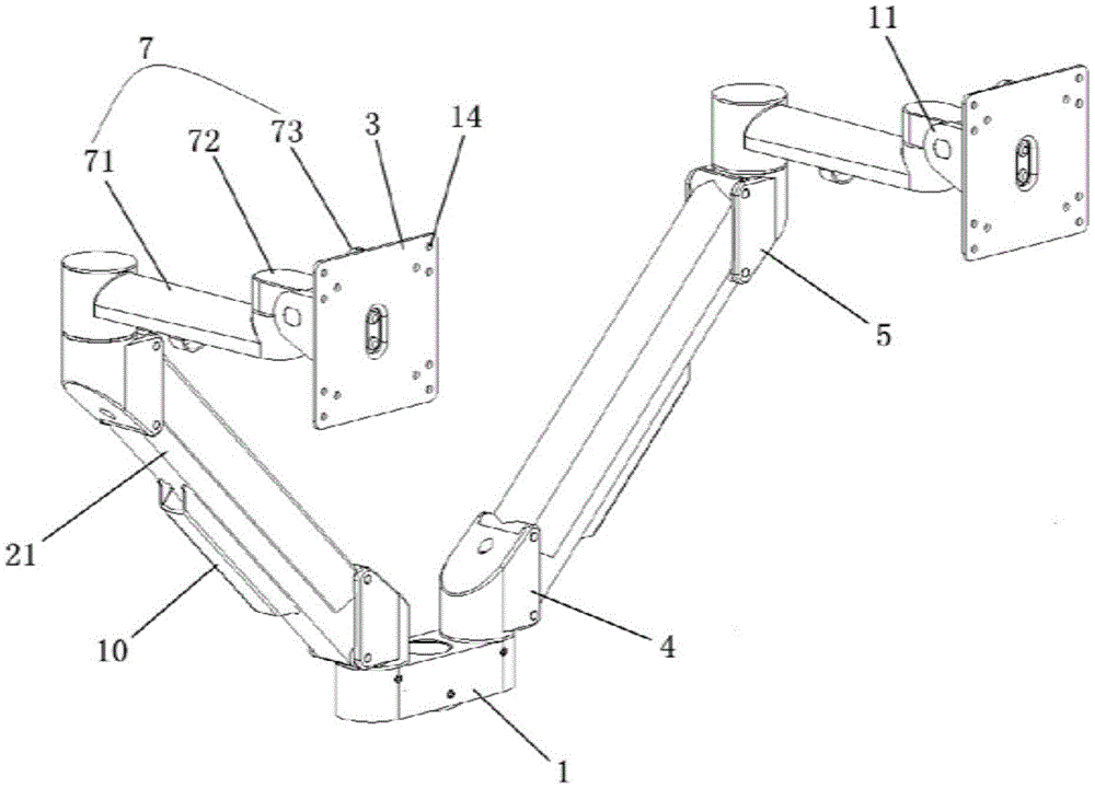
图1为本实用新型优选实施例的整体结构示意图;Fig. 1 is the overall structure schematic diagram of the preferred embodiment of the present utility model;
图2为本实用新型优选实施例的局部剖视图;2 is a partial cross-sectional view of the preferred embodiment of the present utility model;
图3为本实用新型优选实施例的局部结构示意图;Fig. 3 is the partial structure schematic diagram of the preferred embodiment of the present utility model;
图中:1、安装台;2、高度调节机构;21、壳体;22、气体弹簧;3、旋转板;4、第一连接座;5、第二连接座;6、调节组件;61、调节螺杆;62、调节滑块;7、锁紧摆动机构;71、固定杆;72、转动块;73、锁紧组件;731、固定块;732、锁紧板;8、卡槽;9、卡块;10、过线盒;11、轴承座;12、折弯结构;13、挤压斜面;14、安装孔位。In the figure: 1. Installation platform; 2. Height adjustment mechanism; 21. Housing; 22. Gas spring; 3. Rotary plate; 4. First connecting seat; 5. Second connecting seat; 6. Adjusting assembly; 61, Adjusting screw; 62, adjusting slider; 7, locking and swinging mechanism; 71, fixing rod; 72, rotating block; 73, locking assembly; 731, fixing block; 732, locking plate; 8, card slot; 9, Clamping block; 10. Wire box; 11. Bearing seat; 12. Bending structure; 13. Extrusion slope; 14. Installation hole position.
具体实施方式Detailed ways
现在结合附图和实施例对本实用新型作进一步详细的说明,这些附图均为简化的示意图,仅以示意方式说明本实用新型的基本结构,因此其仅显示与本实用新型有关的构成。The present utility model will now be described in further detail with reference to the accompanying drawings and embodiments. These drawings are all simplified schematic diagrams, and only illustrate the basic structure of the present utility model in a schematic manner, so only the structures related to the present utility model are shown.
如图1至图3所示,一种可自由调节的双屏显示器支架,包括安装台1、位于安装台1两端的两组高度调节机构2以及位于高度调节机构2顶端的旋转板3;高度调节机构2包括壳体21与位于壳体21内的气体弹簧22,壳体21底端通过第一连接座4与安装台1连接,壳体21顶端设置有第二连接座5,气体弹簧22一端固定于壳体21内,另一端通过调节组件6与第一连接座4连接,旋转板3通过锁紧摆动机构7与第二连接座5连接,旋转板3上设有安装孔位14,旋转板3可进行自转。As shown in Figures 1 to 3, a freely adjustable dual-screen display stand includes an installation table 1, two sets of
在本实施例中,显示器通过安装孔位14采用螺丝安装在旋转板3上,安装完成之后,当需要对显示器进行高度调节时,可通过按压第二连接座5,在壳体21内的气体弹簧22支撑作用下,实现显示器在一定高度范围内的自由悬停,当显示器过重时,气体弹簧22无法有效地对显示器进行支撑,操作者可使用外部转动杆带动调节螺杆61进行转动,使调节滑块62向下运动,带动气体弹簧22底端向下运动,增大气体弹簧22的负载,从而使其能够对显示器进行有效地支撑,当显示器过轻时,气体弹簧22对显示器的支撑过量,操作者可使用外部转动杆带动调节螺杆61进行转动,使调节滑块62向上运动,带动气体弹簧22底端向上运动,降低气体弹簧22的负载,从而使其能够对显示器进行有效地支撑。In this embodiment, the display is installed on the rotating plate 3 by screws through the
当需要对显示器的角度进行调节时,转动块72以固定杆71一端为轴心进行转动,通过锁紧组件73带动显示器进行转动,实现对显示器的左右位置调节。When the angle of the display needs to be adjusted, the rotating
当显示器需要切换横屏或竖屏时,操作者可转动旋转板3,从而带动显示器进行转动,实现显示器横屏与竖屏的切换。When the display needs to switch between the horizontal screen and the vertical screen, the operator can rotate the rotating plate 3 to drive the display to rotate, so as to realize the switch between the horizontal screen and the vertical screen of the display.
在本实施例中,锁紧组件73在工作时,人工手动将卡块9塞入卡槽8内,在塞入过程中,卡块9受到折弯结构12的阻挡作用,卡块9通过对挤压斜面13进行挤压,使折弯结构12发生形变,从而使卡块9顺利进入卡槽8内,卡块9完全进入卡槽8后,折弯结构12自动复位,对卡块9顶部进行固定锁紧,完成对旋转板3的固定锁紧操作,从而实现对显示器的锁紧定位。In this embodiment, when the
在本实施例中,轴承座11还能够相对转动块72进行转动,从而带动锁紧组件73进行转动,实现对显示器上下倾角度的调节。In this embodiment, the
具体地,在本实施例中,壳体21包括上壳体21与下壳体21,上壳体21与下壳体21配合。Specifically, in this embodiment, the
具体地,上壳体21内设有卡槽8,气体弹簧22一端通过卡块9与卡槽8配合,采用卡槽8与卡块9配合,实现对气体弹簧22一端的固定。Specifically, the
在本实施例中,调节组件6包括调节螺杆61与调节滑块62,调节滑块62与气体弹簧22连接,调节螺杆61能够实现调节滑块62的竖向运动。In this embodiment, the
在本实施例中,壳体21上设置有过线盒10,过线盒10的存在,能够对显示器的导线进行整合,避免出现导线杂乱无章的现象,提高美观性。In the present embodiment, the
具体地,锁紧摆动机构7包括固定杆71、位于固定杆71一端的转动块72以及位于转动块72上的锁紧组件73,固定杆71与第二连接座5相连,转动块72通过旋转轴与固定杆71端部连接。Specifically, the locking and swinging
具体而言,锁紧组件73包括固定块731与位于固定块731内的锁紧板732,旋转板3通过铆钉与锁紧板732连接。Specifically, the locking
在本实施例中,固定块731通过轴承座11与转动块72连接,固定块731上设有容纳槽,锁紧板732位于容纳槽内,锁紧板732顶部设有折弯结构12。In this embodiment, the fixed
具体地,折弯结构12上设有挤压斜面13。Specifically, the bending structure 12 is provided with an
总而言之,本实用新型能够对显示器进行自由调节,高度调节机构2的存在,能够对显示器所处的高度进行调节,锁紧摆动机构7能够实现显示器的角度调节,旋转板3能够实现显示器自身的转动,从而切换横屏与竖屏,相较于传统的双屏显示器支架,能够满足更多需求,操作更为便捷,大大提高用户的使用舒适度,同时该双屏显示器支架结构简单,能够在较小空间内安装,使用方便。All in all, the present utility model can freely adjust the display, the existence of the
以上依据本实用新型的理想实施例为启示,通过上述的说明内容,相关人员完全可以在不偏离本项实用新型技术思想的范围内,进行多样的变更以及修改。本项实用新型的技术性范围并不局限于说明书上的内容,必须要根据权利要求范围来确定技术性范围。The above is inspired by the ideal embodiment of the present invention. Through the above description, relevant persons can make various changes and modifications without departing from the technical idea of the present invention. The technical scope of the present invention is not limited to the content in the description, and the technical scope must be determined according to the scope of the claims.
Claims (9)
Priority Applications (1)
| Application Number | Priority Date | Filing Date | Title |
|---|---|---|---|
| CN201922414332.5U CN211694157U (en) | 2019-12-29 | 2019-12-29 | Double screen display ware support that can freely adjust |
Applications Claiming Priority (1)
| Application Number | Priority Date | Filing Date | Title |
|---|---|---|---|
| CN201922414332.5U CN211694157U (en) | 2019-12-29 | 2019-12-29 | Double screen display ware support that can freely adjust |
Publications (1)
| Publication Number | Publication Date |
|---|---|
| CN211694157U true CN211694157U (en) | 2020-10-16 |
Family
ID=72795926
Family Applications (1)
| Application Number | Title | Priority Date | Filing Date |
|---|---|---|---|
| CN201922414332.5U Expired - Fee Related CN211694157U (en) | 2019-12-29 | 2019-12-29 | Double screen display ware support that can freely adjust |
Country Status (1)
| Country | Link |
|---|---|
| CN (1) | CN211694157U (en) |
Cited By (2)
| Publication number | Priority date | Publication date | Assignee | Title |
|---|---|---|---|---|
| CN112590862A (en) * | 2020-12-17 | 2021-04-02 | 高翔 | Vehicle-mounted terminal equipment for subway rail communication |
| CN113028232A (en) * | 2021-02-25 | 2021-06-25 | 翟桂荣 | Mobile internet-based video and audio fusion cloud platform |
-
2019
- 2019-12-29 CN CN201922414332.5U patent/CN211694157U/en not_active Expired - Fee Related
Cited By (3)
| Publication number | Priority date | Publication date | Assignee | Title |
|---|---|---|---|---|
| CN112590862A (en) * | 2020-12-17 | 2021-04-02 | 高翔 | Vehicle-mounted terminal equipment for subway rail communication |
| CN112590862B (en) * | 2020-12-17 | 2022-12-23 | 高翔 | Vehicle-mounted terminal equipment for subway track communication |
| CN113028232A (en) * | 2021-02-25 | 2021-06-25 | 翟桂荣 | Mobile internet-based video and audio fusion cloud platform |
Similar Documents
| Publication | Publication Date | Title |
|---|---|---|
| US20160348834A1 (en) | Flat panel tv bracket | |
| CN113154202A (en) | Two-arm display support | |
| CN104279412B (en) | Look squarely, look up a step rapid translating support | |
| CN109521839B (en) | Elevation angle adjustable computer display screen | |
| KR101229933B1 (en) | Stands structure of monitor | |
| CN215522541U (en) | Two-arm display support | |
| WO2023202057A1 (en) | Lifting mechanism and height-adjustable table | |
| CN201106739Y (en) | Lifting rotating shaft | |
| CN210831099U (en) | LED display screen mounting structure convenient to use | |
| CN201126707Y (en) | Flat television bracket | |
| CN101494013A (en) | Hanging display | |
| CN217402148U (en) | Support for display screen | |
| CN211667492U (en) | Electronic commerce teaching device | |
| CN212805159U (en) | LED display screen fixing frame | |
| CN201036019Y (en) | Wall-hanging bracket of hook type flat panel display | |
| CN211694164U (en) | Height adjusting mechanism for display support | |
| CN220523757U (en) | Fixing support | |
| CN216202359U (en) | Multi-angle telescopic adjusting television mounting rack | |
| CN221991479U (en) | Universal support frame for display | |
| CN220037915U (en) | Multi-screen display base | |
| CN220287066U (en) | A connection device for LED display screen | |
| CN223768594U (en) | A rotatable and adjustable computer monitor stand structure | |
| CN208156558U (en) | A kind of all-in-one machine | |
| CN218992973U (en) | an adjustable display | |
| CN214151649U (en) | Adjustable bracket for keyboard |
Legal Events
| Date | Code | Title | Description |
|---|---|---|---|
| GR01 | Patent grant | ||
| GR01 | Patent grant | ||
| CF01 | Termination of patent right due to non-payment of annual fee | ||
| CF01 | Termination of patent right due to non-payment of annual fee |
Granted publication date: 20201016 |