CN211682102U - Barrel turning device for manufacturing washing machine - Google Patents
Barrel turning device for manufacturing washing machine Download PDFInfo
- Publication number
- CN211682102U CN211682102U CN201922412165.0U CN201922412165U CN211682102U CN 211682102 U CN211682102 U CN 211682102U CN 201922412165 U CN201922412165 U CN 201922412165U CN 211682102 U CN211682102 U CN 211682102U
- Authority
- CN
- China
- Prior art keywords
- plate
- washing machine
- shaped mounting
- plates
- mounting plate
- Prior art date
- Legal status (The legal status is an assumption and is not a legal conclusion. Google has not performed a legal analysis and makes no representation as to the accuracy of the status listed.)
- Active
Links
- 238000005406 washing Methods 0.000 title claims abstract description 25
- 238000004519 manufacturing process Methods 0.000 title claims abstract description 14
- 230000007246 mechanism Effects 0.000 claims abstract description 24
- 230000008093 supporting effect Effects 0.000 claims description 30
- 238000009434 installation Methods 0.000 abstract description 4
- 230000007306 turnover Effects 0.000 description 3
- 230000009286 beneficial effect Effects 0.000 description 1
- 230000007547 defect Effects 0.000 description 1
- 238000011086 high cleaning Methods 0.000 description 1
- 238000000034 method Methods 0.000 description 1
- XLYOFNOQVPJJNP-UHFFFAOYSA-N water Substances O XLYOFNOQVPJJNP-UHFFFAOYSA-N 0.000 description 1
Images


Abstract
The utility model belongs to the technical field of the washing machine manufacturing technology and specifically relates to a washing machine is made and is used barrel turning device, including two fixed plates, the equal screw thread cartridge in four corners of fixed plate has locking bolt, two the equal horizontally connect in top intermediate position of one side of keeping away from each other of fixed plate has the layer board, the top of layer board all is connected with the backup pad perpendicularly, two vertically between the backup pad be provided with U type mounting panel, all be provided with slide mechanism between the tip of U type mounting panel and the adjacent backup pad. The utility model discloses a set up slide mechanism to can carry out zonulae occludens with U type mounting panel and backup pad, effectively ensure the installation stability of U type mounting panel, simultaneously through setting up actuating mechanism, thereby can drive about carrying out U type mounting panel, be convenient for promote the barrel that two fixture held, conveniently overturn the processing to the barrel, with this intensity of labour who effectively reduces the staff.
Description
Technical Field
The utility model relates to a washing machine makes the field, especially relates to a washing machine makes and uses barrel turning device.
Background
The double-tub washing machine is a washing and dewatering 2-in-one washing machine, and consists of a washing tub and a dewatering tub. The washing and dewatering can be carried out separately, but the water intake and drainage can be completed manually, the washing machine has high cleaning degree, low power consumption and optional washing and dewatering time. The base is installed on the barrel firstly usually in the manufacturing process of the double-barrel washing machine, the barrel is overturned after the installation is finished, other components such as the panel are installed, the existing barrel is overturned manually mostly, the overturning mode is high in labor intensity of workers, and low in working efficiency, and therefore the barrel overturning device for the washing machine is provided.
Disclosure of Invention
The utility model aims at solving the defects of large labor intensity and low working efficiency in the prior art and providing a barrel overturning device for manufacturing a washing machine.
In order to achieve the above purpose, the utility model adopts the technical scheme that: a drum overturning device for manufacturing a washing machine comprises two fixing plates, locking bolts are inserted into four corners of each fixing plate in a threaded manner, supporting plates are horizontally connected to the middle positions of the tops of the two fixing plates, the tops of the two fixing plates are far away from each other, the top ends of the supporting plates are vertically connected with supporting plates, a U-shaped mounting plate is vertically arranged between the two supporting plates, sliding mechanisms are arranged between the end part of the U-shaped mounting plate and the adjacent supporting plate, a driving mechanism is arranged at the top of the supporting plate, a clamping mechanism is arranged on one side of the U-shaped mounting plate, which is close to the two ends of the U-shaped mounting plate, the clamping mechanism comprises a vertically arranged rotating plate, the rotating plate is rotatably connected with the end part of the U-shaped mounting plate through a rotating shaft, and a cylinder is fixedly arranged on one side, away from the U-shaped mounting plate, of the rotating plate, and a clamping disc is fixedly connected to the end of the cylinder.
Preferably, slide mechanism includes the vertical rectangle through-hole of seting up in the backup pad, the equal vertical spacing slide bar that is connected with in inside both sides of rectangle through-hole, two the common slip cover in the outside of spacing slide bar is equipped with the slide, U type mounting panel and slide fixed connection, just the spacing slide bar outside of slide bottom all overlaps and is equipped with supporting spring.
Preferably, the bottom of rotor plate all fixed mounting have the balancing weight, the arc spacing groove has all been seted up on the top of rotor plate, the tip one corner of U type mounting panel all be connected with perpendicularly with the spacing post of arc spacing groove assorted.
Preferably, the side surface of the clamping disc is bonded with an anti-slip pad, and the anti-slip pad is made of anti-slip rubber.
Preferably, actuating mechanism includes the electric putter of installing perpendicularly on the backup pad top, electric putter's top fixedly connected with roof, roof fixed connection is on U type mounting panel top.
Compared with the prior art, the utility model discloses following beneficial effect has:
the utility model discloses a set up slide mechanism to can carry out zonulae occludens with U type mounting panel and backup pad, effectively ensure the installation stability of U type mounting panel, simultaneously through setting up actuating mechanism, thereby can drive about carrying out U type mounting panel, be convenient for promote the barrel that two fixture held, conveniently overturn the processing to the barrel, with this intensity of labour who effectively reduces the staff.
Drawings
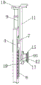
Fig. 1 is a schematic structural view of a drum turnover device for manufacturing a washing machine according to the present invention;
fig. 2 is a schematic sectional structural view of a drum turnover device for manufacturing a washing machine according to the present invention;
fig. 3 is an enlarged schematic view of a portion a in fig. 1.
In the figure: the device comprises a fixing plate 1, a locking bolt 2, a supporting plate 3, a supporting plate 4, a rectangular through hole 5, a supporting spring 6, a sliding seat 7, a limiting sliding rod 8, an electric push rod 9, a top plate 10, a U-shaped mounting plate 11, an anti-slip pad 12, a limiting column 13, a rotating shaft 14, a clamping disc 15, a rotating plate 16, an air cylinder 17, an arc-shaped limiting groove 18 and a balancing weight 19.
Detailed Description
The following description is presented to disclose the invention so as to enable any person skilled in the art to practice the invention. The preferred embodiments in the following description are given by way of example only, and other obvious variations will occur to those skilled in the art.
As shown in fig. 1-3, a drum turnover device for manufacturing a washing machine comprises two fixing plates 1, locking bolts 2 are inserted into four corners of each fixing plate 1 through threads, a supporting plate 3 is horizontally connected to the middle position of the top of one side of each fixing plate 1, the top end of each supporting plate 3 is vertically connected with a supporting plate 4, a U-shaped mounting plate 11 is vertically arranged between the two supporting plates 4, a sliding mechanism is arranged between the end part of each U-shaped mounting plate 11 and the adjacent supporting plate 4, a driving mechanism is arranged at the top of each supporting plate 4, a clamping mechanism is arranged at one side of each U-shaped mounting plate 11, which is close to each other, and comprises a vertically arranged rotating plate 16, the rotating plate 16 is rotatably connected with the end part of each U-shaped mounting plate 11 through a rotating shaft 14, an air cylinder 17 is fixedly arranged at one side of the rotating plate 16, which is far, the side surface of the clamping disc 15 is bonded with an anti-skid pad 12, and the anti-skid pad 12 is made of anti-skid rubber; through setting up fixed plate 1 and locking bolt 2, thereby can be with this device fixed mounting on the line body, through setting up pivot 14, thereby be convenient for rotate rotor plate 16 and U type mounting panel 11 and be connected, through being connected cylinder 17 and outside air supply, thereby can drive clamping disk 15 and carry out the centre gripping to the barrel, make things convenient for actuating mechanism to promote the barrel, simultaneously through setting up slipmat 12, thereby the phenomenon of sideslipping appears in the in-process of centre gripping can be convenient for, effectively improve the stability of centre gripping.
The sliding mechanism comprises a rectangular through hole 5 vertically formed in a supporting plate 4, two sides of the inside of the rectangular through hole 5 are vertically connected with limiting slide rods 8, the outer sides of the two limiting slide rods 8 are jointly slidably sleeved with a sliding seat 7, a U-shaped mounting plate 11 is fixedly connected with the sliding seat 7, supporting springs 6 are sleeved on the outer sides of the limiting slide rods 8 at the bottom of the sliding seat 7, the driving mechanism comprises an electric push rod 9 vertically mounted at the top end of the supporting plate 4, the top end of the electric push rod 9 is fixedly connected with a top plate 10, and the top plate 10 is fixedly connected to the top; through setting up spacing slide bar 8 and slide 7, thereby can carry out zonulae occludens with U type mounting panel 11 and backup pad 4, effectively ensure U type mounting panel 11's installation stability, can play good supporting effect through supporting spring 6 simultaneously, and be connected electric putter 9 and external power source, thereby can drive from top to bottom U type mounting panel 11, be convenient for promote the barrel that two fixture held, the convenience is overturn the processing to the barrel, with this intensity of labour who effectively reduces the staff.
The bottom ends of the rotating plates 16 are fixedly provided with balancing weights 19, the top ends of the rotating plates 16 are provided with arc-shaped limiting grooves 18, and one corner of the end part of the U-shaped mounting plate 11 is vertically connected with a limiting column 13 matched with the arc-shaped limiting grooves 18; through setting up arc spacing groove 18 and spacing post 13 to can carry on spacingly to the rotation angle of rotor plate 16, simultaneously through setting up balancing weight 19, thereby the automatic rotor plate 16 that drives resets after the barrel upset finishes, makes things convenient for next continuation operation.
The utility model discloses: at first, fix the centre gripping through two fixture to the barrel on the line body, drive about the centre gripping finishes through actuating mechanism to U type mounting panel 11, be convenient for promote the barrel that two fixture gripped, make things convenient for the staff to carry out upset processing to the barrel to this effectively reduces staff's intensity of labour.
The foregoing shows and describes the general principles, essential features, and advantages of the invention. It will be understood by those skilled in the art that the present invention is not limited to the above embodiments, and that the principles of the present invention may be applied to any other embodiment without departing from the spirit and scope of the present invention. The scope of the invention is defined by the appended claims and equivalents thereof.
Claims (5)
1. A drum overturning device for manufacturing a washing machine comprises two fixing plates (1), wherein locking bolts (2) are inserted into four corners of each fixing plate (1) in a threaded manner, and the drum overturning device is characterized in that the middle positions of the tops of the two fixing plates (1) far away from one side are horizontally connected with supporting plates (3), the top ends of the supporting plates (3) are vertically connected with supporting plates (4), a U-shaped mounting plate (11) is vertically arranged between the two supporting plates (4), sliding mechanisms are arranged between the end part of the U-shaped mounting plate (11) and the adjacent supporting plates (4), a driving mechanism is arranged at the top of each supporting plate (4), clamping mechanisms are arranged on the sides, close to each other, of the two ends of the U-shaped mounting plate (11), each clamping mechanism comprises a vertically arranged rotating plate (16), and the rotating plates (16) are rotatably connected with the end parts of the U-shaped mounting plates (11) through, and a cylinder (17) is fixedly mounted on one side, away from the U-shaped mounting plate (11), of the rotating plate (16), and a clamping disc (15) is fixedly connected to the end part of the cylinder (17).
2. The drum overturning device for the washing machine manufacturing according to claim 1, wherein the sliding mechanism comprises a rectangular through hole (5) vertically formed in the supporting plate (4), both sides of the inside of the rectangular through hole (5) are vertically connected with limit slide bars (8), the outer sides of the two limit slide bars (8) are jointly slidably sleeved with a sliding seat (7), the U-shaped mounting plate (11) is fixedly connected with the sliding seat (7), and the outer sides of the limit slide bars (8) at the bottom of the sliding seat (7) are sleeved with supporting springs (6).
3. The drum overturning device for the washing machine manufacturing according to claim 1, wherein the bottom ends of the rotating plates (16) are fixedly provided with balancing weights (19), the top ends of the rotating plates (16) are provided with arc-shaped limiting grooves (18), and one corner of the end part of the U-shaped mounting plate (11) is vertically connected with a limiting column (13) matched with the arc-shaped limiting grooves (18).
4. The drum overturning device for the washing machine manufacturing according to claim 1, wherein a non-slip pad (12) is bonded to a side surface of the clamping disc (15), and the non-slip pad (12) is made of non-slip rubber.
5. The drum overturning device for the washing machine manufacturing according to claim 1, characterized in that the driving mechanism comprises an electric push rod (9) vertically installed on the top end of the supporting plate (4), the top end of the electric push rod (9) is fixedly connected with a top plate (10), and the top plate (10) is fixedly connected on the top end of a U-shaped mounting plate (11).
Priority Applications (1)
| Application Number | Priority Date | Filing Date | Title |
|---|---|---|---|
| CN201922412165.0U CN211682102U (en) | 2019-12-28 | 2019-12-28 | Barrel turning device for manufacturing washing machine |
Applications Claiming Priority (1)
| Application Number | Priority Date | Filing Date | Title |
|---|---|---|---|
| CN201922412165.0U CN211682102U (en) | 2019-12-28 | 2019-12-28 | Barrel turning device for manufacturing washing machine |
Publications (1)
| Publication Number | Publication Date |
|---|---|
| CN211682102U true CN211682102U (en) | 2020-10-16 |
Family
ID=72795855
Family Applications (1)
| Application Number | Title | Priority Date | Filing Date |
|---|---|---|---|
| CN201922412165.0U Active CN211682102U (en) | 2019-12-28 | 2019-12-28 | Barrel turning device for manufacturing washing machine |
Country Status (1)
| Country | Link |
|---|---|
| CN (1) | CN211682102U (en) |
Cited By (1)
| Publication number | Priority date | Publication date | Assignee | Title |
|---|---|---|---|---|
| CN116985082A (en) * | 2023-09-25 | 2023-11-03 | 新乐电器(江苏)有限公司 | Barrel overturning device for manufacturing washing machine |
-
2019
- 2019-12-28 CN CN201922412165.0U patent/CN211682102U/en active Active
Cited By (2)
| Publication number | Priority date | Publication date | Assignee | Title |
|---|---|---|---|---|
| CN116985082A (en) * | 2023-09-25 | 2023-11-03 | 新乐电器(江苏)有限公司 | Barrel overturning device for manufacturing washing machine |
| CN116985082B (en) * | 2023-09-25 | 2023-12-12 | 新乐电器(江苏)有限公司 | Barrel overturning device for manufacturing washing machine |
Similar Documents
| Publication | Publication Date | Title |
|---|---|---|
| CN211682102U (en) | Barrel turning device for manufacturing washing machine | |
| CN209408103U (en) | A kind of multifunctional process equipment for energy saving hollow glass | |
| CN110369757A (en) | A kind of device with clamp system for steel plate finishing | |
| CN209323025U (en) | A kind of automobile parts surface electrophoresis hanging apparatus | |
| CN110640700A (en) | Intelligent manufacturing, processing and overturning device applied to plate-type workpiece | |
| CN213377380U (en) | Door leaf turnover machine | |
| CN211805325U (en) | Timber surface grinding device for furniture production | |
| CN208997907U (en) | A kind of rack convenient for adjusting color lamp position | |
| CN207739399U (en) | A kind of friction antiskid bearing applied to steel construction | |
| CN214559604U (en) | Sanding device for automatically overturning wood board | |
| CN213945487U (en) | Automobile repair welding device | |
| CN214213033U (en) | Frock clamp of curved surface spare part for auto-parts | |
| CN210649260U (en) | Sheet metal welding clamp | |
| CN213735768U (en) | Prevent to press from both sides glassware pad pasting device of dirt | |
| CN210965740U (en) | Automobile ABS circuit board shell gluing device | |
| CN208514213U (en) | A kind of plate grinding device | |
| CN209140192U (en) | A kind of shipbuilding welding fixture | |
| CN209025463U (en) | Auxiliary tool is used in a kind of installation of curtain skeleton | |
| CN208163576U (en) | A kind of central vehicle decorative panel general assembly workbench | |
| CN208046376U (en) | A kind of building motor mounting rack convenient for adjusting | |
| CN110026322A (en) | A kind of automobile door cover mounting table and its application | |
| CN211967099U (en) | Environmental protection timber surface finish device | |
| CN213159766U (en) | Air purifier filter screen cleaning device | |
| CN220559704U (en) | Drying rack for plate baking varnish | |
| CN220728868U (en) | Feeding equipment for plank dryer |
Legal Events
| Date | Code | Title | Description |
|---|---|---|---|
| GR01 | Patent grant | ||
| GR01 | Patent grant | ||
| TR01 | Transfer of patent right |
Effective date of registration: 20240202 Address after: No. 83 Nanwan Village, Sihai Town, Yanqing District, Beijing, 100000 Patentee after: Song Shuxia Country or region after: China Address before: Room 909, No. 689, Tianhe North Road, Tianhe District, Guangzhou, Guangdong 510630 Patentee before: Guangzhou jiakana cosmetics development Co.,Ltd. Country or region before: China |
|
| TR01 | Transfer of patent right |