CN211672370U - A dewatering device for chinese cabbage processing - Google Patents
A dewatering device for chinese cabbage processing Download PDFInfo
- Publication number
- CN211672370U CN211672370U CN202020130561.4U CN202020130561U CN211672370U CN 211672370 U CN211672370 U CN 211672370U CN 202020130561 U CN202020130561 U CN 202020130561U CN 211672370 U CN211672370 U CN 211672370U
- Authority
- CN
- China
- Prior art keywords
- chinese cabbage
- dewatering
- electric telescopic
- dewatering box
- dehydration
- Prior art date
- Legal status (The legal status is an assumption and is not a legal conclusion. Google has not performed a legal analysis and makes no representation as to the accuracy of the status listed.)
- Active
Links
- 235000010149 Brassica rapa subsp chinensis Nutrition 0.000 title claims abstract description 33
- 235000000536 Brassica rapa subsp pekinensis Nutrition 0.000 title claims abstract description 33
- 241000499436 Brassica rapa subsp. pekinensis Species 0.000 title claims abstract description 33
- 230000018044 dehydration Effects 0.000 claims abstract description 26
- 238000006297 dehydration reaction Methods 0.000 claims abstract description 26
- XLYOFNOQVPJJNP-UHFFFAOYSA-N water Substances O XLYOFNOQVPJJNP-UHFFFAOYSA-N 0.000 abstract description 4
- 238000003754 machining Methods 0.000 abstract description 3
- 239000000463 material Substances 0.000 abstract description 3
- 235000013311 vegetables Nutrition 0.000 description 5
- 238000000034 method Methods 0.000 description 4
- 235000013305 food Nutrition 0.000 description 2
- 239000000126 substance Substances 0.000 description 2
- 241000196324 Embryophyta Species 0.000 description 1
- 241000233866 Fungi Species 0.000 description 1
- 230000009286 beneficial effect Effects 0.000 description 1
- 235000005911 diet Nutrition 0.000 description 1
- 230000037213 diet Effects 0.000 description 1
- 238000005516 engineering process Methods 0.000 description 1
- 229910052500 inorganic mineral Inorganic materials 0.000 description 1
- 239000011707 mineral Substances 0.000 description 1
- 235000015097 nutrients Nutrition 0.000 description 1
- 235000013343 vitamin Nutrition 0.000 description 1
- 229940088594 vitamin Drugs 0.000 description 1
- 229930003231 vitamin Natural products 0.000 description 1
- 239000011782 vitamin Substances 0.000 description 1
Images


Landscapes
- Preparation Of Fruits And Vegetables (AREA)
Abstract
The utility model discloses a dewatering device for chinese cabbage processing, including the dewatering box, the outside at dewatering box top is connected with the apron through the second mounting panel, and connects through second fastening screw between apron and the second mounting panel, the upper and lower both ends equidistance of dewatering box surface distributes and has two sets of slide bars, and the surface of slide bar has the third backup pad through slide swing joint. The utility model discloses set up third electric telescopic handle, the fourth backup pad, the dehydration motor, an apron, the second fastening screw, second mounting panel and dewatering box, can reach the purpose of carrying out dehydration to the chinese cabbage in the dewatering box, second electric telescopic handle has been set up, pivot and first electric telescopic handle, can make things convenient for people to fall the material and adjust to the inclination of dewatering box, through the cooperation of above structure, the machining efficiency of chinese cabbage has effectively been improved, and adopt mechanical dehydration, can get rid of the water that the chinese cabbage surface was stained with and attaches fast, thereby the quality of chinese cabbage has been improved.
Description
Technical Field
The utility model relates to a chinese cabbage processing technology field specifically is a dewatering device for chinese cabbage processing.
Background
Vegetables are plants or fungi which can be used as vegetables and can be cooked into food, the vegetables are one of the essential foods in daily diet of people, the vegetables can provide various vitamins and mineral substances and other nutrient substances necessary for human bodies, the Chinese cabbages are one kind of vegetables, the Chinese cabbages need to be cleaned in the processing process, the surfaces of the Chinese cabbages are stained with a lot of water after being cleaned, and therefore the Chinese cabbages need to be dried.
SUMMERY OF THE UTILITY MODEL
An object of the utility model is to provide a dewatering device for chinese cabbage processing to solve the problem that proposes among the above-mentioned background art.
In order to achieve the above object, the utility model provides a following technical scheme: a dewatering device for Chinese cabbage processing comprises a dewatering box, wherein the outer side of the top of the dewatering box is connected with a cover plate through a second mounting plate, the cover plate is connected with the second mounting plate through a second fastening screw, two groups of slide bars are equidistantly distributed at the upper end and the lower end of the outer surface of the dewatering box, the outer surface of each slide bar is movably connected with a third support plate through a slide seat, the periphery of the top of the third support plate is fixedly connected with a second support plate of a bottom part which is movably connected with a fourth support plate through a third electric telescopic rod, a dewatering motor of which an output shaft is fixedly connected with the middle end of the top of the cover plate is fixedly arranged at the middle end of the bottom of the fourth support plate, the front side and the rear side of the left end of the top of the second support plate are both movably connected with second electric telescopic rods through rotating, and the tops of the first electric telescopic rod and the second electric telescopic rod are movably connected with a first supporting plate through a rotating shaft.
Preferably, a first reserved groove is formed in the middle end of the bottom of the dewatering box, a second reserved groove of the inner surface sliding connection baffle is formed in the bottom of the dewatering box and located in the outer side of the first reserved groove, clamping grooves are formed in the front end and the rear end of the left side and the rear end of the right side of the baffle, and a threaded hole of the inner surface threaded connection first fastening screw is formed in the outer side of the inner cavity of the dewatering box and located in the second reserved groove.
Preferably, first reservation groove is circular structure, and second reservation groove and baffle are square structure, and the middle-end fixed mounting on the positive surface of baffle has the handle, and simultaneously, the dehydration hole has all been seted up in the internal surface of baffle and the outside of dehydration case.
Preferably, apron and drain box are circular structure, and second mounting panel and slide are the loop configuration, and the second through-hole has all been seted up with the junction of second fastening screw to apron and second mounting panel, and the quantity of every group slide bar is four to eight, and the contained angle between per two adjacent slide bars is the same, and every equal sliding connection of slide bar is in the inner chamber of slide, and simultaneously, the third backup pad is the arc structure, and the radian is the same with the radian of slide.
Preferably, the front side and the rear side of the left end of the bottom of the first supporting plate are fixedly connected with a first mounting plate through a support, and first through holes are formed in the periphery of the inner surface of the first mounting plate.
Compared with the prior art, the beneficial effects of the utility model are as follows:
1. the utility model is provided with a third electric telescopic rod, a fourth supporting plate, a dewatering motor, a cover plate, a second fastening screw, a second mounting plate and a dewatering box, people firstly pour the Chinese cabbage to be dewatered from the top of the dewatering box, then the third electric telescopic rod is controlled by an external controller to extend, so that the cover plate is contacted with the top of the dewatering box, then the second fastening screw is screwed by an external wrench, so that the cover plate and the second mounting plate are fixed, the dewatering motor is opened by the external controller, the dewatering motor can drive the cover plate, the second mounting plate and the dewatering box to rotate while rotating, thereby achieving the purpose of dewatering the Chinese cabbage in the dewatering box, the second electric telescopic rod, the rotating shaft and the first electric telescopic rod are arranged, when people need to adjust the overall height of the dewatering box, the second electric telescopic rod and the first electric telescopic rod extend or contract simultaneously through the external controller, thereby make things convenient for people to fall the material, when people need adjust the inclination of dehydration box, through the extension of external controller control second electric telescopic handle or the extension of first electric telescopic handle to realize adjusting the purpose of dehydration box inclination, satisfy the dehydration demand under the different situation, through the cooperation of above structure, effectively improved the machining efficiency of chinese cabbage, and adopt mechanical dehydration, can get rid of the water that the chinese cabbage surface was stained with and attaches fast, thereby improved the quality of chinese cabbage.
2. The utility model discloses set up slide, slide bar and third backup pad, can ensure the stability of dewatering box at the rotation in-process.
Drawings
The accompanying drawings, which are included to provide a further understanding of the application and are incorporated in and constitute a part of this application, illustrate embodiment(s) of the application and together with the description serve to explain the application and not to limit the application, and in which:
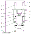
FIG. 1 is a schematic structural view of the present invention;
FIG. 2 is a schematic top view of the slide carriage of the present invention;
FIG. 3 is a schematic view of a three-dimensional structure of a third supporting plate of the present invention;
FIG. 4 is an enlarged schematic view of the structure at the position A of the present invention;
fig. 5 is an enlarged schematic view of the position B of the present invention.
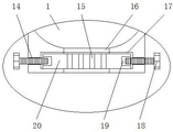
In the figure: the device comprises a dewatering box 1, a sliding seat 2, a sliding rod 3, a dewatering motor 4, a third supporting plate 5, a second electric telescopic rod 6, a support 7, a first supporting plate 8, a first electric telescopic rod 9, a second supporting plate 10, a third electric telescopic rod 11, a first mounting plate 12, a first through hole 13, a threaded hole 14, a dewatering hole 15, a first reserved groove 16, a second reserved groove 17, a first fastening screw 18, a clamping groove 19, a baffle plate 20, a second through hole 21, a cover plate 22, a second fastening screw 23, a second mounting plate 24 and a fourth supporting plate 25.
Detailed Description
The technical solution in the embodiments of the present invention will be clearly and completely described below with reference to the accompanying drawings in the embodiments of the present invention.
Referring to fig. 1-5, a dewatering device for processing Chinese cabbage comprises a dewatering box 1, a first reserved groove 16 is disposed at the middle end of the bottom of the dewatering box 1, a second reserved groove 17 slidably connected with a baffle 20 is disposed at the bottom of the dewatering box 1 and located outside the first reserved groove 16, a clamping groove 19 is disposed at each of the front and rear ends of each of the left and right sides of the baffle 20, a threaded hole 14 connected with a first fastening screw 18 through an inner surface thread is disposed at the outer side of the second reserved groove 17 in the inner cavity of the dewatering box 1, the first reserved groove 16 is of a circular structure, the second reserved groove 17 and the baffle 20 are of a square structure, a handle is fixedly mounted at the middle end of the front surface of the baffle 20, dewatering holes 15 are disposed at the inner surface of the baffle 20 and the outer side of the dewatering box 1, after dewatering is completed, the first fastening screw 18 is screwed out from the threaded hole 14 through an external wrench, the tail end of a first fastening screw 18 is separated from the inner cavity of a clamping groove 19, then a baffle plate 20 is pulled out from the inner cavity of a second reserved groove 17 through a handle, the outer side of the top of a dewatering box 1 is connected with a cover plate 22 through a second mounting plate 24, the cover plate 22 is connected with the second mounting plate 24 through a second fastening screw 23, two groups of sliding rods 3 are distributed at the upper end and the lower end of the outer surface of the dewatering box 1 at equal intervals, the outer surface of each sliding rod 3 is movably connected with a third supporting plate 5 through a sliding seat 2, the stability of the dewatering box 1 in the rotating process can be guaranteed, the cover plate 22 and the dewatering box 1 are both in a circular structure, the second mounting plate 24 and the sliding seat 2 are both in an annular structure, second through holes 21 are respectively formed at the connecting positions of the cover plate 22, the second mounting plate 24 and the second fastening screw 23, the number of each group of the sliding, every slide bar 3 all sliding connection in the inner chamber of slide 2, and simultaneously, third backup pad 5 is the arc structure, and the radian is the same with slide 2's radian, the top fixedly connected with bottom of third backup pad 5 is all around through second backup pad 10 of third electric telescopic handle 11 swing joint fourth backup pad 25, and the middle-end fixed mounting of fourth backup pad 25 bottom has output shaft and the middle-end fixed connection's of apron 22 top dehydration motor 4, people pour the chinese cabbage that waits to dewater into from the top of dehydration case 1 earlier, then control the extension of third electric telescopic handle 11 through external controller, make apron 22 and the top contact of dehydration case 1, then tighten second fastening screw 23 through external spanner, make fixed between apron 22 and the second mounting panel 24, rethread external controller opens dehydration motor 4, dehydration motor 4 can drive apron 22 when the rotation, The second mounting plate 24 and the dewatering box 1 rotate, so as to achieve the purpose of dewatering the Chinese cabbages in the dewatering box 1, the front side and the rear side of the left end of the top of the second support plate 10 are movably connected with the second electric telescopic rods 6 through rotating shafts, the front side and the rear side of the right end of the top of the second support plate 10 are movably connected with the first electric telescopic rods 9 through rotating shafts, and the tops of the first electric telescopic rods 9 and the second electric telescopic rods 6 are movably connected with the first support plate 8 through rotating shafts, when people need to adjust the whole height of the dewatering box 1, the second electric telescopic rods 6 and the first electric telescopic rods 9 extend or contract simultaneously through an external controller, so as to facilitate the dumping of people, when people need to adjust the inclination angle of the dewatering box 1, the external controller controls the extension of the second electric telescopic rods 6 or the extension of the first electric telescopic rods 9, so as to achieve the purpose of adjusting the inclination, satisfy the dehydration demand under the different situation, first mounting panel 12 of support 7 fixedly connected with is passed through to both sides around the 8 bottom left ends of first backup pad, and first through-hole 13 has all been seted up all around to first mounting panel 12 internal surface (external controller is the PLC controller in this application, and simultaneously, two wiring ends of external controller are connected with power plug through the wire, and adopt the commercial power to supply power in this application).
When the device is used, the third electric telescopic rod 11, the fourth supporting plate 25, the dewatering motor 4, the cover plate 22, the second fastening screw 23, the second mounting plate 24 and the dewatering box 1 are arranged, people firstly pour the Chinese cabbages to be dewatered from the top of the dewatering box 1, then the extension of the third electric telescopic rod 11 is controlled by the external controller, the cover plate 22 is contacted with the top of the dewatering box 1, then the second fastening screw 23 is screwed by the external wrench, the cover plate 22 and the second mounting plate 24 are fixed, the dewatering motor 4 is opened by the external controller, the dewatering motor 4 can drive the cover plate 22, the second mounting plate 24 and the dewatering box 1 to rotate while rotating, thereby achieving the purpose of dewatering the Chinese cabbages in the dewatering box 1, the second electric telescopic rod 6, the rotating shaft and the first electric telescopic rod 9 are arranged, when people need to adjust the whole height of the dewatering box 1, through external controller while second electric telescopic handle 6 and the extension of first electric telescopic handle 9 or shrink, thereby make things convenient for people to fall the material, when people need adjust the inclination of dehydration box 1, through the extension of external controller control second electric telescopic handle 6 or the extension of first electric telescopic handle 9, thereby realize adjusting the purpose of dehydration box 1 inclination, satisfy the dehydration demand under the different situation, cooperation through above structure, the machining efficiency of chinese cabbage has effectively been improved, and adopt mechanical dehydration, can get rid of the water that the chinese cabbage surface was stained with and attaches, thereby the quality of chinese cabbage has been improved, slide 2 has been set up, slide bar 3 and third backup pad 5, can ensure the stability of dehydration box 1 at the rotation in-process.
Claims (5)
1. The utility model provides a dewatering device for chinese cabbage processing, includes dehydration tank (1), its characterized in that: the outer side of the top of the dewatering box (1) is connected with a cover plate (22) through a second mounting plate (24), the cover plate (22) is connected with the second mounting plate (24) through a second fastening screw (23), two groups of sliding rods (3) are distributed at equal intervals at the upper end and the lower end of the outer surface of the dewatering box (1), the outer surface of each sliding rod (3) is movably connected with a third supporting plate (5) through a sliding seat (2), the periphery of the top of each third supporting plate (5) is fixedly connected with a second supporting plate (10) of a fourth supporting plate (25) through a third electric telescopic rod (11), the middle end of the bottom of each fourth supporting plate (25) is fixedly provided with a dewatering motor (4) with an output shaft fixedly connected with the middle end of the top of the cover plate (22), and the front side and the rear side of the left end of the top of each second supporting plate (10) are movably connected, both sides all have first electric telescopic handle (9) through pivot swing joint around second backup pad (10) top right-hand member, and the top of first electric telescopic handle (9) and second electric telescopic handle (6) has first backup pad (8) through pivot swing joint.
2. The dewatering device for Chinese cabbage processing according to claim 1, characterized in that: first reservation groove (16) have been seted up to the middle-end of dehydration case (1) bottom, second reservation groove (17) of internal surface sliding connection baffle (20) have been seted up in the bottom of dehydration case (1) and the outside that is located first reservation groove (16), draw-in groove (19) have all been seted up at both ends around baffle (20) the left and right sides, screw hole (14) of the first fastening screw of internal surface threaded connection (18) have been seted up in the inner chamber of dehydration case (1) and the outside that is located second reservation groove (17).
3. The dewatering device for Chinese cabbage processing according to claim 2, characterized in that: first reservation groove (16) are circular structure, and second reservation groove (17) and baffle (20) are square structure, and the middle-end fixed mounting on the positive surface of baffle (20) has the handle, and simultaneously, dehydration hole (15) have all been seted up in the internal surface of baffle (20) and the outside of dehydration case (1).
4. The dewatering device for Chinese cabbage processing according to claim 1, characterized in that: apron (22) and dewatering box (1) are circular structure, second mounting panel (24) and slide (2) are the loop configuration, and apron (22) and second mounting panel (24) all seted up second through-hole (21) with the junction of second fastening screw (23), the quantity of every group slide bar (3) is four to eight, and the contained angle between per two adjacent slide bars (3) is the same, equal sliding connection in the inner chamber of slide (2) in every slide bar (3), and simultaneously, third backup pad (5) are the arc structure, and the radian is the same with the radian of slide (2).
5. The dewatering device for Chinese cabbage processing according to claim 1, characterized in that: both sides pass through support (7) fixedly connected with first mounting panel (12) around first backup pad (8) bottom left end, and first through-hole (13) have all been seted up all around to first mounting panel (12) internal surface.
Priority Applications (1)
| Application Number | Priority Date | Filing Date | Title |
|---|---|---|---|
| CN202020130561.4U CN211672370U (en) | 2020-01-20 | 2020-01-20 | A dewatering device for chinese cabbage processing |
Applications Claiming Priority (1)
| Application Number | Priority Date | Filing Date | Title |
|---|---|---|---|
| CN202020130561.4U CN211672370U (en) | 2020-01-20 | 2020-01-20 | A dewatering device for chinese cabbage processing |
Publications (1)
| Publication Number | Publication Date |
|---|---|
| CN211672370U true CN211672370U (en) | 2020-10-16 |
Family
ID=72773799
Family Applications (1)
| Application Number | Title | Priority Date | Filing Date |
|---|---|---|---|
| CN202020130561.4U Active CN211672370U (en) | 2020-01-20 | 2020-01-20 | A dewatering device for chinese cabbage processing |
Country Status (1)
| Country | Link |
|---|---|
| CN (1) | CN211672370U (en) |
Cited By (1)
| Publication number | Priority date | Publication date | Assignee | Title |
|---|---|---|---|---|
| CN114216304A (en) * | 2021-12-16 | 2022-03-22 | 宜宾职业技术学院 | Machining draining device and using method |
-
2020
- 2020-01-20 CN CN202020130561.4U patent/CN211672370U/en active Active
Cited By (1)
| Publication number | Priority date | Publication date | Assignee | Title |
|---|---|---|---|---|
| CN114216304A (en) * | 2021-12-16 | 2022-03-22 | 宜宾职业技术学院 | Machining draining device and using method |
Similar Documents
| Publication | Publication Date | Title |
|---|---|---|
| CN211672370U (en) | A dewatering device for chinese cabbage processing | |
| CN206619557U (en) | A kind of convenient low-voltage electrical apparatus installed | |
| CN108295952A (en) | A kind of reciprocation cycle food processing material pressing device not changing motor steering | |
| CN203679129U (en) | Full automatic steel pipe thread rolling machine | |
| CN108199672A (en) | A kind of adjustable solar-cell panel support | |
| CN208390106U (en) | A kind of reciprocation cycle food processing material pressing device not changing motor steering | |
| CN208876231U (en) | A kind of food processing apparatus for food baking | |
| CN206294820U (en) | A kind of brown sugar Gu method boils jacketed pan | |
| CN211246796U (en) | Seafood is crushing equipment for extract product | |
| CN213966186U (en) | Stirring device of frying pan | |
| CN211823573U (en) | Summer sleeping mat drying device with adjustable area | |
| CN210399711U (en) | Fluidized bed dryer | |
| CN211552242U (en) | Centrifugal dewatering equipment | |
| CN207844414U (en) | A kind of manipulator loading and unloading overturning structure | |
| CN207574465U (en) | A kind of process equipment of sweet potato noodles | |
| CN208957503U (en) | A kind of household plant rack that plummer is height-adjustable | |
| CN208547175U (en) | A kind of navel orange processing fruit wax drying unit | |
| CN206098545U (en) | Formation machine | |
| CN105214797A (en) | Raw material pressing device is used in a kind of fish meal processing | |
| CN206227606U (en) | A kind of fish bean curd former | |
| CN218200296U (en) | Green tea fixation controllable speed feeding device | |
| CN206781391U (en) | A kind of furniture decoration line punching press fixing device | |
| CN205056160U (en) | Device is squeezed with raw materials to fish meal processing | |
| CN213599705U (en) | Bean product drying device convenient to spread out | |
| CN219236250U (en) | Sesame paste production is with squeezing separator |
Legal Events
| Date | Code | Title | Description |
|---|---|---|---|
| GR01 | Patent grant | ||
| GR01 | Patent grant | ||
| TR01 | Transfer of patent right | ||
| TR01 | Transfer of patent right |
Effective date of registration: 20240511 Address after: Room 401, Unit 2, Building 6, Rainbow City, Binjiang District, Hangzhou City, Zhejiang Province, 310000 Patentee after: Chen Guo Country or region after: China Address before: 734502 eco industrial park, Minle County, Zhangye, Gansu Patentee before: Zhangye Caiyuan Trading Co.,Ltd. Country or region before: China |