CN211670724U - Electric control reciprocating motion type liposuction device - Google Patents
Electric control reciprocating motion type liposuction device Download PDFInfo
- Publication number
- CN211670724U CN211670724U CN202020541180.5U CN202020541180U CN211670724U CN 211670724 U CN211670724 U CN 211670724U CN 202020541180 U CN202020541180 U CN 202020541180U CN 211670724 U CN211670724 U CN 211670724U
- Authority
- CN
- China
- Prior art keywords
- needle
- liposuction
- motor
- bearing
- shell
- Prior art date
- Legal status (The legal status is an assumption and is not a legal conclusion. Google has not performed a legal analysis and makes no representation as to the accuracy of the status listed.)
- Expired - Fee Related
Links
Images


Landscapes
- Transmission Devices (AREA)
Abstract
The utility model belongs to the technical field of liposuction plasticity in medical plastic surgery, and relates to an electric control reciprocating motion type liposuction device; comprises a shell, a motor, a spring hose, a sliding block, a liposuction needle, a synchronous gear, a synchronous belt, a bearing type synchronous gear, a needle seat groove and a motor shaft; the right end of the front side wall of the shell is provided with a motor, a motor shaft penetrates into the inner cavity of the shell, the output end of the motor shaft is provided with a synchronous gear, the synchronous gear is connected with a bearing type synchronous gear through a synchronous belt, and the bearing type synchronous gear is arranged at the left end of the shell; the lower half part of the synchronous belt is provided with a sliding block, the lower end of the sliding block is provided with a needle seat groove, the needle seat groove is connected with a needle seat clamping groove at the rear end of the liposuction needle, the needle seat is fixedly connected with one end of a spring hose, and the other end of the spring hose is connected with the tail part of the machine shell; the device main part is rational in infrastructure, convenient operation, and the security is high, has alleviateed operating personnel's fatigue degree, has alleviated medical personnel's pressure.
Description
The technical field is as follows:
the utility model belongs to the technical field of the plastic nature of fat suction of medical plastic cosmetology surgery, a rely on motor conveyer belt, fat suction needle matched with liposuction device, especially an automatically controlled reciprocating motion formula liposuction ware.
Background art:
the liposuction operation belongs to one of the body sculpturing operations of plastic and cosmetic surgery, and its principle is that the excess fat of a certain position of human body is sucked out by means of negative pressure suction so as to attain the goal of quickly slimming local body. The common parts of the whole body for fat absorption include the face, the two chin, the neck, the shoulder and back, the four limbs, the hands and feet, the upper abdomen, the lower abdomen, the side waist, the upper buttocks, the reduction of the buttocks, the lifting of the buttocks, and the like.
Liposuction has become increasingly popular in large cities. In the early 90 s of the last century, liposuction gradually exploded; fat loss through liposuction has become a trivial undertaking, and as with double-edged eyelid and nose augmentation, it has become one of the most common cosmetic and plastic programs. There are many methods for liposuction, such as electric method, syringe method, ultrasonic method, resonance liposuction, Korean layering liposuction and skin firming method, and electronic liposuction.
The conventional liposuction surgery is a liposuction surgery, and is performed in such a manner that a small hole is cut in a surgical site, a liposuction needle is inserted into a fat layer, and then the fat is sucked out by using the negative pressure of a liposuction machine. Because the diameter of the needle tube of the liposuction needle is 2.5mm, and the fat layer is thick and solid and is not easy to suck out, the traditional operation using the liposuction needle needs a doctor to hold the liposuction needle to pump the liposuction needle back and forth at the operation position. For this reason, the operation generally takes a long time, and the strain on the arm muscles caused by the long-time hand operation of the doctor can cause the doctor to feel tired.
In the prior art, chinese patent publication No. CN205549083U discloses a liposuction needle with a rotation function, which includes a mounting housing, a hollow motor, a connector, a needle tube, a liposuction hole, a scraper, a liposuction tube, and a negative pressure pump, wherein the liposuction needle with a rotation function is configured to insert the needle tube into a human body, start the hollow motor, drive the needle tube to rotate, scrape down fat under the action of the scraper, and then start the negative pressure pump, so that the inside of the mounting housing and the inside of the needle tube are vacuumed by the negative pressure pump through the liposuction tube, and the fat in the human body is extracted through the liposuction hole; chinese patent application publication No. CN203836552U discloses a two-way control liposuction device, which comprises a housing, a piston and a plunger; the shell is provided with a piston cavity and a plunger cavity which are communicated, and the diameter of the piston cavity is larger than that of the plunger cavity; the piston is connected with the plunger, and the piston and the plunger are respectively in sliding sealing fit with the piston cavity and the plunger cavity; the two ends of the piston cavity are respectively provided with an oil port, the side wall of the plunger cavity is provided with an oil suction port with one-way oil inlet, and the right end of the plunger cavity is provided with an oil discharge port with one-way oil outlet; the piston moves leftwards to drive the plunger to open the oil suction opening. When oil ports at two ends of the piston cavity supply oil alternately, the piston can reciprocate in the piston cavity and drive the plunger to reciprocate, in the reciprocating motion process of the plunger, the plunger cavity absorbs lubricating grease by the oil suction port, and the oil discharge port discharges the lubricating grease.
In a word, because the diameter of the liposuction needle is small, and the fat layer of a human body is thick and cannot be easily sucked out, a doctor holds the liposuction needle by hand to suck the fat repeatedly for a long time to generate fatigue, and the fatigue of the doctor can influence the liposuction effect and even cause an accident; at present, reciprocating fat suction and suction equipment specially applied to the beauty fat suction industry does not exist, the manual fat suction efficiency is low, the fat suction time is long, and the effect is poor.
The utility model has the following contents:
the utility model aims to overcome the shortcoming that prior art exists, use inconvenient, the manual efficiency low grade not enough to current liposuction device, under the condition that guarantees that the user conveniently operates, saves the cost, design an automatically controlled reciprocating motion formula liposuction ware.
In order to achieve the purpose, the utility model relates to an electrically controlled reciprocating motion type liposuction device, which comprises a main structure comprising a casing, a motor seat, a spring hose, a slide block, a liposuction needle, a synchronous gear, a synchronous belt, a needle fixing hole, a bearing type synchronous gear, a needle seat groove, a seat nut and a motor shaft; the left end face, the right end face and the lower end face of the cuboid-shaped casing are not sealed, an L-shaped motor base is fixedly mounted at the right end of the front side wall of the casing in a threaded mode through a base nut, a motor is mounted on the motor base and provided with a motor shaft, the motor shaft penetrates into the inner cavity of the casing from the front side wall of the casing, a synchronizing gear is fixedly arranged at the output end of the motor shaft and is connected with a bearing type synchronizing gear through a synchronizing belt, and the bearing type synchronizing gear is mounted at the left end of the casing; the lower half part of the annular synchronous belt is fixedly provided with a sliding block, the lower end of the sliding block is provided with a needle seat groove with an open groove structure, the needle seat groove is connected with a needle seat clamping groove at the rear end of the liposuction needle in a groove mode, and one side of the sliding block is provided with a needle fixing hole, so that after the needle seat of the liposuction needle is inserted into the needle seat groove, the needle seat of the liposuction needle is screwed into the needle fixing hole by a screw to clamp the liposuction needle, and the liposuction needle is prevented from slipping, rotating; the needle seat at the tail part of the liposuction needle is fixedly connected with one end of the spring hose, the other end of the spring hose is connected with the tail part of the machine shell, the tail part of the machine shell is connected with the liposuction hose, and the liposuction hose is connected to a liposuction vacuum machine.
The motor shaft on the fixed frame bearing that is provided with of nested formula, frame bearing adopts deep groove ball formula bearing structure, motor shaft and frame bearing's shaft hole medial surface fixed connection, frame bearing installs in the preceding lateral wall of casing, frame bearing's outside curved surface and the preceding lateral wall fixed connection of casing.
The middle part of the bearing type synchronous gear is fixedly provided with a gear bearing with the same axis, an optical shaft is fixedly arranged in a bearing hole of the gear bearing, two ends of the optical shaft are limited in grooves symmetrically formed in the front side wall and the rear side wall of the shell respectively, the grooves are in U-shaped structures, the grooved open groove structures can facilitate the disassembly of the synchronous belt and the bearing type synchronous gear, and simultaneously play a role in adjusting the tightness of the synchronous belt, and the existence of the grooves is also convenient for replacing the synchronous belts with different lengths, so that the synchronous belt is suitable for the movement with different strokes; one end of the optical axis is fixedly connected with a clamping device arranged on the front side wall of the shell, and the other end of the optical axis is fixedly connected with a clamping device arranged on the rear side wall of the shell.
The clamping device of the utility model consists of a screw rod, a fixed nut, a clamping device nut and a shaft collar, wherein the fixed nut is fixed on the side wall of the casing, the screw rod penetrates into the fixed nut and is fixedly connected with the screw thread of the fixed nut, one end of the screw rod is provided with the shaft collar, the shaft hole of the shaft collar is fixedly connected with the end part of the optical axis, the clamping device nut is arranged on the screw rod in a threaded manner, the clamping device nut is arranged between the fixed nut and the shaft collar, and the clamping device nut is tightly attached and fixed with the fixed; the clamping device nut and the fixing nut are screwed to the clamping position according to the length of the synchronous belt, so that the effect of pre-tightening the synchronous belt is achieved, the synchronous belt is prevented from vibrating and shaking, and meanwhile the synchronous belt and the bearing type synchronous gear are convenient to detach and replace.
Slider and apron are fixed through the blind nut with synchronous belt clamp in the middle of, the face that the apron contacted with synchronous belt is provided with the tooth of being connected with synchronous belt can mesh, prevents that synchronous belt is not hard up, skids between apron and slider.
There is coil spring among the spring hose, and spring hose can follow its seesaw when the liposuction needle gos forward the backstroke, and spring hose can not take place to curl, deformation when returning.
The lower extreme installation of casing has the needle limit frame, and the needle limit frame is in the same end of casing with bearing type synchronous gear, and the middle part of needle limit frame is provided with limit faller, and the needle through-hole has been seted up to limit faller middle part level, and the front portion of liposuction needle passes from the needle through-hole, and the diameter size of needle through-hole is the same with the diameter size of liposuction needle or slightly is greater than the diameter size of liposuction needle, and the effect of needle through-hole is: the phenomenon of swing and the like of the liposuction needle in the motion process is limited, and the functions of guiding, limiting, fixing, supporting and the like are achieved.
The slider only at synchronous gear, synchronous belt and bearing formula synchronous gear's lower extreme reciprocating motion, the stroke of slider motion can be realized controlling by motor controller through speed, acceleration, number of turns, time, the pulse frequency of adjusting motor reversal, motor and motor controller electricity information connection.
Motor controller adopt current motor controller structure, motor controller is provided with demonstration and control panel, motor controller can carry out the parameter setting according to user's demand on demonstration and control panel to reach the purpose of the different functional mode of speed, acceleration, number of turns, time, pulse frequency and switching motor that control motor just reverses.
The motor controller of the utility model is connected with a power supply through a transformer; according to the model of the motor controller, the type of the transformer is selected from a 220V-to-12V type transformer or a 220V-to-24V type transformer.
Compared with the prior art, the utility model, the automatically controlled reciprocating motion formula liposuction ware main part that designs is rational in infrastructure, and the principle is reliable, and it possesses following beneficial effect: 1. the fat suction needle for the traditional fat suction operation is reserved, and compared with an injector method, ultrasonic waves, resonance fat suction and the like, the fat suction needle has higher safety and higher public acceptance degree.
2. The mechanical and electric technology replaces manual operation, so that the operability and the technicality of manual operation are reduced, meanwhile, the fatigue degree of operators is reduced, and the pressure and the fatigue of medical workers are relieved.
3. The display and control panel is added, the motor can be debugged and controlled to work in different modes, and the motor control device is suitable for various occasions.
4. The tail of the liposuction needle is connected with the tail of the spring hose, and the spring hose is internally provided with the spiral spring, so that the phenomena of curling, knotting and the like of the hose when the liposuction needle advances and retreats are improved.
5. The clamping device at the front end of the liposuction device is convenient for mounting, dismounting and replacing the synchronous gear and the synchronous belt, and the pre-tightening device can meet the requirements of mounting belts with different lengths, so that the movement range and the function of the liposuction needle are improved.
6. The appearance design of the electric control reciprocating motion type liposuction device is a handheld device, the device is convenient for medical care personnel to hold, the shape and the size accord with the man-machine engineering, the operation is convenient, the structure is simple, and the holding is not tired.
Description of the drawings:
fig. 1 is a schematic diagram of the front view structure of the electrically controlled reciprocating fat sucker according to the present invention.
Fig. 2 is a schematic view of the structure principle of the electric control reciprocating type liposuction device according to the present invention.
Fig. 3 is a schematic view of the structure principle of the liposuction needle according to the present invention.
Fig. 4 is a schematic view of the structure principle of the rotating disc and the lower fixed ring after the crust of the electric control reciprocating motion type liposuction device of the utility model is removed.
Fig. 5 is a schematic view of the structure principle of the clamping device according to the present invention.
Fig. 6 is a schematic view of a structural principle of the motor according to the present invention.
Fig. 7 is a schematic view of the structural principle of the slider according to the present invention.
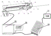
FIG. 8 is a schematic diagram of the principle of the structure of the electric reciprocating fat sucker and the motor controller
The specific implementation mode is as follows:
the present invention will be further described with reference to the following examples and accompanying drawings.
Example (b):
the main structure of the electrically-controlled reciprocating motion type liposuction device related to the embodiment comprises a machine shell 1, a motor 2, a motor base 3, a spring hose 4, a sliding block 5, a liposuction needle 6, a slot 7, a fixing nut 8, a clamping device 9, a synchronous gear 10, a synchronous belt 11, a needle fixing hole 12, an optical axis 13, a bearing type synchronous gear 14, a needle limiting plate 15, a needle limiting frame 16, a needle base 17, a needle base slot 18, a needle through hole 19, a cover plate 20, a gear bearing 21, a cover plate nut 22, a machine base nut 23, a clamping device nut 24, a shaft collar 25, a machine base bearing 26, a motor shaft 27, a transformer 28, a motor controller 29 and a display and control panel 30; the rectangular cabinet 1 has left and right end faces and lower end faces which are not closed, the right end of the front side wall of the cabinet 1 is fixedly provided with an L-shaped motor base 3 in a threaded manner through a base nut 23, the motor base 3 is provided with a motor 2, the motor 2 is provided with a motor shaft 27, the motor shaft 27 penetrates into the inner cavity of the cabinet 1 from the front side wall of the cabinet 1, the motor shaft 27 is fixedly provided with a base bearing 26 in a nested manner, the base bearing 26 adopts a deep groove ball bearing structure, the motor shaft 27 is fixedly connected with the inner side face of a shaft hole of the base bearing 26, the base bearing 26 is arranged in the front side wall of the cabinet 1, the outer curved surface of the base bearing 26 is fixedly connected with the front side wall of the cabinet 1, and the base bearing 26 reduces power loss caused by friction of the motor shaft; the output end of the motor shaft 27 is fixedly provided with a synchronous gear 10, the synchronous gear 10 is connected with a bearing type synchronous gear 14 through a synchronous belt 11, and the bearing type synchronous gear 14 is arranged at the left end of the machine shell 1; when the motor 2 rotates forwards and backwards in a reciprocating manner, the synchronous gear 10 is driven to rotate, the synchronous gear 10 drives the synchronous belt 11 to move forwards and backwards, and then drives the bearing type synchronous gear 14 at the other end to rotate; a gear bearing 21 is coaxially and fixedly installed in the middle of the bearing type synchronous gear 14, an optical shaft 13 is fixedly installed in a bearing hole of the gear bearing 21, two ends of the optical shaft 13 are limited in slots 7 respectively symmetrically formed in the front side wall and the rear side wall of the shell 1, the slots 7 are in a U-shaped structure, the open slot structure of the slots 7 can facilitate the detachment of the synchronous belt 11 and the bearing type synchronous gear 14, and meanwhile, the tightness of the synchronous belt 11 can be adjusted, the synchronous belts 11 with different lengths can be replaced conveniently due to the existence of the slots 7, and the synchronous belt adjusting device is suitable for movement with different strokes; one end of the optical axis 13 is fixedly connected with the clamping device 9 arranged on the front side wall of the machine shell 1, and the other end of the optical axis is fixedly connected with the clamping device 9 arranged on the rear side wall of the machine shell 1; the clamping device 9 is composed of a screw rod, a fixing nut 8, a clamping device nut 24 and a shaft collar 25, the fixing nut 8 is fixed on the side wall of the machine shell 1, the screw rod penetrates through the fixing nut 8 and is fixedly connected with the fixing nut 8 in a threaded mode, the shaft collar 25 is arranged at one end of the screw rod, a shaft hole of the shaft collar 25 is fixedly connected with the end portion of the optical axis 13, the clamping device nut 24 is installed on the screw rod in a threaded mode, the clamping device nut 24 is arranged between the fixing nut 8 and the shaft collar 25, and the clamping device nut 24 is tightly attached and fixed with the; the clamping device nut 24 and the fixing nut 8 are screwed to the clamping position according to the length of the synchronous belt 11, so that the function of pre-tightening the synchronous belt 11 is achieved, the synchronous belt 11 is prevented from vibrating and shaking, and the synchronous belt 11 and the bearing type synchronous gear 14 are convenient to disassemble and replace; the lower half part of the annular synchronous belt 11 is fixedly provided with a sliding block 5, the sliding block 5 and a cover plate 20 clamp the synchronous belt 11 in the middle and are fixed through a cover plate nut 22, and the surface of the cover plate 20, which is in contact with the synchronous belt 11, is provided with teeth which can be meshed and connected with the synchronous belt 11, so that the synchronous belt 11 is prevented from loosening and slipping between the cover plate 20 and the sliding block 5; the lower end of the sliding block 5 is provided with a needle seat groove 18 with an open groove structure, the needle seat groove 18 is connected with a needle seat 17 at the rear end of the liposuction needle 6 in a clamping groove mode, one side of the sliding block 5 is provided with a needle fixing hole 12, and the needle seat 17 of the liposuction needle 6 is inserted into the needle seat groove 18 and then screwed in from the needle fixing hole 12 by a screw to clamp the liposuction needle 6 so as to prevent the liposuction needle 6 from slipping, rotating and falling off in the working process; the needle seat 17 at the tail part of the liposuction needle 6 is not directly connected with a hose (the hose is used for conveying extracted fat), but the needle seat 17 is fixedly connected with one end of the spring hose 4, the other end of the spring hose 4 is connected with the tail part of the machine shell 1, then the tail part of the machine shell 1 is connected with the liposuction hose, and the liposuction hose is connected to a liposuction vacuum machine; the spring hose 4 functions as: compared with a hose, the hose is firmer and more durable, the spring hose 4 is internally provided with the spiral spring, the spring hose 4 can move back and forth along with the hose when the liposuction needle 6 moves forwards and backwards, and the spring hose 4 cannot be curled, deformed and the like when the liposuction needle moves back; the lower extreme installation of casing 1 has limit needle frame 16, and limit needle frame 16 is located the same end of casing 1 with bearing formula synchronous gear 14, and limit needle frame 16's middle part sets up limit faller 15, and limit faller 15 middle part level has seted up needle through-hole 19, and the front portion of liposuction needle 6 passes from needle through-hole 19, and the diameter size of needle through-hole 19 is the same with the diameter size of liposuction needle 6 or slightly is greater than the diameter size of liposuction needle 6, and the effect of needle through-hole 19 is: the phenomenon of swing and the like of the liposuction needle 6 in the motion process is limited, and the functions of guiding, limiting, fixing, supporting and the like are achieved.
The slide block 5 related to the embodiment reciprocates only at the lower ends of the synchronous gear 10, the synchronous belt 11 and the bearing type synchronous gear 14, the moving stroke of the slide block 5 can be controlled by adjusting the speed, the acceleration, the number of turns, the time, the pulse frequency and the like of the motor 2 through the motor controller 29, and the motor 2 is electrically and informationally connected with the motor controller 29.
The motor controller 29 related to the embodiment adopts the existing motor controller structure, the motor controller 29 is provided with the display and control panel 30, and the motor controller 29 can be arranged on the display and control panel 30 according to the requirements of users, so that the speed, the acceleration, the number of turns, the time, the pulse frequency of the positive and negative rotation of the motor 2 can be controlled, and different functional modes of the motor 2 can be switched.
The motor controller 29 according to the present embodiment is connected to the power supply 31 through the transformer 28, and the selection of the motor 2, the transformer 28, and the motor controller 29 can be varied. The transformer 28 can select 220V to 12V, 220V to 24V, and the like.
The electric control reciprocating motion type liposuction device related to the embodiment belongs to a handheld device, the design is only an internal structure, and the appearance design can be diversified; the device is convenient for medical personnel to hold, and the shape size accords with human-machine engineering, convenient operation, and simple structure holds not tired.
The electric control reciprocating motion type liposuction device related to the embodiment has the working principle that: the motor 2 converts the electric energy into the mechanical energy for driving the synchronous gear 10 to rotate, and then drives the synchronous belt 11 and the bearing type synchronous gear 14 to move, so that the sliding block 5 fixed on the synchronous belt 11 can drive the liposuction needle 6 to do reciprocating motion circularly, the electric energy is converted into the rotary mechanical energy, and the rotary mechanical energy is converted into the linear motion mechanical energy. Specifically, a transformer 28 converts 220V voltage into 24V voltage and sends the 24V voltage to a motor controller 29, the motor controller 29 is adjustable, the motor controller 29 can control the reciprocating forward and reverse rotation speed, acceleration, number of turns, time, pulse frequency and the like of a motor 2, the motor controller 29 generates pulse signals and sends the pulse signals to the motor 2, the motor 2 rotates forward and reverse to drive a synchronous gear 10 on a motor shaft 27 to rotate, a synchronous belt 11 is installed on the synchronous gear 10, a bearing type synchronous gear 14 is installed at the other end of the synchronous belt 11, and the synchronous gear 10 continuously rotates forward and reverse to drive the synchronous belt 11 to continuously move forward and backward. The lower end of the synchronous belt 11 is fixed with a sliding block 5, the sliding block 5 is pressed and fixed on the synchronous belt 11 through a cover plate 20, the sliding block 5 moves back and forth continuously along with the synchronous belt 11, the liposuction needle 6 is inserted and fixed in the sliding block 5, after the needle seat 17 is pressed by a screw from a needle fixing hole 12 on one side of the sliding block 5, the liposuction needle 6 moves back and forth along with the sliding block 5, and the mechanical purpose of back and forth movement of the liposuction needle 6 is achieved.
Claims (10)
1. An automatically controlled reciprocating motion formula liposuction ware which characterized in that: the automatic lubricating device comprises a shell, a motor base, a spring hose, a sliding block, a grease suction needle, a synchronous gear, a synchronous belt, a needle fixing hole, a bearing type synchronous gear, a needle base groove, a base nut and a motor shaft; the left end face, the right end face and the lower end face of the cuboid-shaped casing are not sealed, an L-shaped motor base is fixedly mounted at the right end of the front side wall of the casing in a threaded mode through a base nut, a motor is mounted on the motor base and provided with a motor shaft, the motor shaft penetrates into the inner cavity of the casing from the front side wall of the casing, a synchronizing gear is fixedly arranged at the output end of the motor shaft and is connected with a bearing type synchronizing gear through a synchronizing belt, and the bearing type synchronizing gear is mounted at the left end of the casing; a sliding block is fixedly arranged on the lower half part of the annular synchronous belt, a needle seat groove with an open groove structure is arranged at the lower end of the sliding block, the needle seat groove is connected with a needle seat clamping groove at the rear end of the liposuction needle in a clamping manner, a needle fixing hole is formed in one side of the sliding block, and a screw can be screwed into the needle fixing hole to clamp the liposuction needle; the needle seat at the tail part of the liposuction needle is fixedly connected with one end of the spring hose, the other end of the spring hose is connected with the tail part of the machine shell, the tail part of the machine shell is connected with the liposuction hose, and the liposuction hose is connected to a liposuction vacuum machine.
2. The electrically controlled reciprocating liposuction device according to claim 1, wherein: the motor shaft is fixedly provided with a machine base bearing in a nested manner, the machine base bearing adopts a deep groove ball type bearing structure, the motor shaft is fixedly connected with the inner side surface of a shaft hole of the machine base bearing, the machine base bearing is arranged in the front side wall of the machine shell, and the outer side curved surface of the machine base bearing is fixedly connected with the front side wall of the machine shell.
3. An electrically controlled reciprocating liposuction device according to claim 2, wherein: the middle part of the bearing type synchronous gear is fixedly provided with a gear bearing with the same axis, an optical shaft is fixedly arranged in a bearing hole of the gear bearing, two ends of the optical shaft are limited in grooves which are symmetrically formed in the front side wall and the rear side wall of the shell respectively, the grooves are of U-shaped structures, one end of the optical shaft is fixedly connected with a clamping device arranged on the front side wall of the shell, and the other end of the optical shaft is fixedly connected with a clamping device arranged on the rear side wall of the shell.
4. An electrically controlled reciprocating liposuction device according to claim 3, wherein: the clamping device is composed of a screw rod, a fixing nut, a clamping device nut and a shaft collar, the fixing nut is fixed on the side wall of the shell, the screw rod penetrates through the fixing nut and is fixedly connected with the fixing nut in a threaded mode, the shaft collar is arranged at one end of the screw rod, the shaft hole of the shaft collar is fixedly connected with the end portion of the optical axis, the clamping device nut is installed on the screw rod in a threaded mode, the clamping device nut is arranged between the fixing nut and the shaft collar, and the clamping device nut and the fixing nut are tightly attached and.
5. An electrically controlled reciprocating liposuction device according to claim 2 or claim 4, wherein: the synchronous belt clamp is fixed between the sliding block and the cover plate through the cover plate nut, and the surface of the cover plate, which is in contact with the synchronous belt, is provided with teeth which can be meshed with the synchronous belt.
6. An electrically controlled reciprocating liposuction device according to claim 5, wherein: the spring hose is internally provided with a spiral spring, and can move back and forth along with the liposuction needle when the liposuction needle moves forwards and backwards, and the spring hose cannot curl or deform when the liposuction needle moves backwards.
7. The electrically controlled reciprocating liposuction device according to claim 6, wherein: the lower end of the machine shell is provided with a needle limiting frame, the needle limiting frame and the bearing type synchronous gear are located at the same end of the machine shell, a needle limiting plate is arranged in the middle of the needle limiting frame, a needle through hole is horizontally formed in the middle of the needle limiting plate, the front portion of the grease suction needle penetrates through the needle through hole, and the diameter size of the needle through hole is the same as or slightly larger than that of the grease suction needle.
8. The electrically controlled reciprocating liposuction device according to claim 7, wherein: the sliding block only reciprocates at the lower ends of the synchronous gear, the synchronous belt and the bearing type synchronous gear, the moving stroke of the sliding block can be controlled by the motor controller through adjusting the speed, the acceleration, the number of turns, the time and the pulse frequency of the motor in the reverse rotation, and the motor is in electrical information connection with the motor controller.
9. The electrically controlled reciprocating liposuction device according to claim 8, wherein: the motor controller adopts the existing motor controller structure, is provided with a display and control panel, and can set parameters on the display and control panel according to the requirements of users.
10. The electrically controlled reciprocating liposuction device according to claim 9, wherein: the motor controller is connected with a power supply through a transformer; according to the model of the motor controller, the type of the transformer is selected from a 220V-to-12V type transformer or a 220V-to-24V type transformer.
Priority Applications (1)
| Application Number | Priority Date | Filing Date | Title |
|---|---|---|---|
| CN202020541180.5U CN211670724U (en) | 2020-04-14 | 2020-04-14 | Electric control reciprocating motion type liposuction device |
Applications Claiming Priority (1)
| Application Number | Priority Date | Filing Date | Title |
|---|---|---|---|
| CN202020541180.5U CN211670724U (en) | 2020-04-14 | 2020-04-14 | Electric control reciprocating motion type liposuction device |
Publications (1)
| Publication Number | Publication Date |
|---|---|
| CN211670724U true CN211670724U (en) | 2020-10-13 |
Family
ID=72743246
Family Applications (1)
| Application Number | Title | Priority Date | Filing Date |
|---|---|---|---|
| CN202020541180.5U Expired - Fee Related CN211670724U (en) | 2020-04-14 | 2020-04-14 | Electric control reciprocating motion type liposuction device |
Country Status (1)
| Country | Link |
|---|---|
| CN (1) | CN211670724U (en) |
Cited By (1)
| Publication number | Priority date | Publication date | Assignee | Title |
|---|---|---|---|---|
| CN114366185A (en) * | 2022-01-15 | 2022-04-19 | 湖南夏龙医疗器械制造股份有限公司 | Man-machine linkage intelligent reciprocating liposuction handle device |
-
2020
- 2020-04-14 CN CN202020541180.5U patent/CN211670724U/en not_active Expired - Fee Related
Cited By (1)
| Publication number | Priority date | Publication date | Assignee | Title |
|---|---|---|---|---|
| CN114366185A (en) * | 2022-01-15 | 2022-04-19 | 湖南夏龙医疗器械制造股份有限公司 | Man-machine linkage intelligent reciprocating liposuction handle device |
Similar Documents
| Publication | Publication Date | Title |
|---|---|---|
| CN205515986U (en) | Portable electronic micropin injection appearance | |
| CN211670724U (en) | Electric control reciprocating motion type liposuction device | |
| CN103006342B (en) | Teeth cleaning device | |
| CN110976148A (en) | Spraying and oiling equipment for circuit board | |
| CN113694361A (en) | Powder and liquid medicine applicator for thoracic surgery | |
| CN109223480B (en) | Handheld massager with replaceable massage head | |
| JP6789463B1 (en) | Electric syringe aid | |
| CN208733080U (en) | A kind of field of biotechnology is moved with plaque takes device | |
| CN202568509U (en) | Pulse transmission device for tooth cleaning machine | |
| CN214209167U (en) | Take little electric current of EMS beauty instrument of face | |
| CN216962973U (en) | Muscle massage device | |
| CN215426636U (en) | Intelligent negative pressure subcutaneous electronic injector control boosting device | |
| CN211095916U (en) | Fascia gun | |
| CN221578747U (en) | Massager for relaxing muscles | |
| CN207856013U (en) | Pulse flushing device | |
| CN215537032U (en) | Novel cosmetic liposuction ware | |
| CN221557052U (en) | Novel suction gun of cupping device | |
| CN221636619U (en) | Negative pressure massager | |
| CN214762133U (en) | Leg massage device for old people nursing | |
| CN217391272U (en) | Air extracting gun of cupping device | |
| CN221787398U (en) | Automatic dispensing system for syringe | |
| CN220210164U (en) | Beauty needle transmission mechanism | |
| CN213589519U (en) | MTS super nano microcrystal skin beautifying gun | |
| CN219355074U (en) | Essence beauty instrument | |
| CN217219782U (en) | Can dismantle electron injection pen of syringe needle fast |
Legal Events
| Date | Code | Title | Description |
|---|---|---|---|
| GR01 | Patent grant | ||
| GR01 | Patent grant | ||
| CF01 | Termination of patent right due to non-payment of annual fee | ||
| CF01 | Termination of patent right due to non-payment of annual fee |
Granted publication date: 20201013 Termination date: 20210414 |