CN211623897U - Assembled heavy support and hanger - Google Patents
Assembled heavy support and hanger Download PDFInfo
- Publication number
- CN211623897U CN211623897U CN202020181705.9U CN202020181705U CN211623897U CN 211623897 U CN211623897 U CN 211623897U CN 202020181705 U CN202020181705 U CN 202020181705U CN 211623897 U CN211623897 U CN 211623897U
- Authority
- CN
- China
- Prior art keywords
- bottom plate
- plate
- bolt
- hanger
- column
- Prior art date
- Legal status (The legal status is an assumption and is not a legal conclusion. Google has not performed a legal analysis and makes no representation as to the accuracy of the status listed.)
- Active
Links
Images


Abstract
The utility model relates to an assembled heavy support hanger, which comprises at least one group of upright posts and at least one group of cross beams; the group of beams are connected with the group of upright posts through section steel connecting pieces; the profile steel connecting piece comprises a first bottom plate and a connecting plate; the first bottom plate and the connecting plate are vertical to each other; the first bottom plate is provided with a plurality of connecting holes; the connecting plate is provided with a clamping groove; a top connecting piece is inserted at the top of the upright post; the top connecting piece comprises a second bottom plate and a connecting column; the connecting column is vertically welded on the second bottom plate; the upright post, the cross beam, the first bottom plate, the connecting plate, the second bottom plate and the connecting column are all provided with a plurality of bolt connecting holes; the first bottom plate is connected with the upright post through a bolt; the connecting plate is connected with the cross beam through bolts; the connecting column is connected with the upright column through a bolt. The utility model provides a factory site operation's problem has improved security and installation effectiveness.
Description
Technical Field
The utility model relates to an assembly type structure technical field, in particular to heavy gallows of assembled.
Background
The traditional welding support needs on-site cutting and welding, needs a plurality of devices, and has poor safety in cutting and firing operation. In the installation, the integral hoisting difficulty is high, and the welding is carried out at a high place when construction is needed. The welding consumes a large amount of labor and has a long welding operation period. In summary, the welding operation has the disadvantages of low safety, long construction period and the like.
Therefore, the traditional welding bracket is replaced by the assembled heavy support and hanger at present. The product is suitable for the field of large-scale pipeline installation, and aims to replace the traditional welding bracket mode, realize the mode of factory pre-production and construction site quick installation. In original scheme welded support mode, the building site often need cut, welding operation, and the construction degree of difficulty is big, and the construction cycle is long, and hoist and mount difficulty, holistic security is lower relatively. The design aims at solving the problem of factory field operation, and the mode of connecting by the fastening piece is used for replacing welding operation, so that the safety and the installation efficiency are improved.
SUMMERY OF THE UTILITY MODEL
Not enough to prior art, the utility model discloses a heavy gallows of assembled.
The utility model discloses the technical scheme who adopts as follows:
an assembled heavy support and hanger comprises at least one group of upright columns and at least one group of cross beams; the group of beams are connected with the group of columns through section steel connecting pieces; the profile steel connecting piece comprises a first bottom plate and a connecting plate; the first bottom plate and the connecting plate are perpendicular to each other; the first bottom plate is provided with a plurality of connecting holes; the connecting plate is provided with a clamping groove; a top connecting piece is inserted into the top of the upright post; the top connecting piece comprises a second bottom plate and a connecting column; the connecting column is vertically welded on the second bottom plate; a plurality of bolt connecting holes are formed in the upright post, the cross beam, the first bottom plate, the connecting plate, the second bottom plate and the connecting column; the first bottom plate is connected with the upright post through a bolt; the connecting plate is connected with the cross beam through bolts; the connecting column is connected with the upright column through bolts.
The method is further characterized in that: the width of the connecting plate is smaller than that of the first bottom plate.
The method is further characterized in that: the central line of the connecting column and the central line of the second bottom plate are on the same straight line.
The method is further characterized in that: the bolt connecting hole of the first bottom plate is rectangular.
The method is further characterized in that: the shape of the bolt connecting hole of the cross beam, the shape of the bolt connecting hole of the connecting plate and the shape of the bolt connecting hole of the second bottom plate are circular.
The method is further characterized in that: the shape of the bolt connecting hole of the upright post and the shape of the bolt connecting hole of the connecting column are both square.
The method is further characterized in that: the stand with the spliced pole is square pipe.
The method is further characterized in that: the beam is H-shaped steel.
The utility model has the advantages as follows:
1. the utility model discloses chooseing for use side's pipe that punches a hole, adopting rigid connection's connected mode, improve the whole bearing capacity of support, reduced the probability that the incident takes place, improved the security.
2. The utility model discloses a bolted connection's connected mode, spare part are at factory's modularization production, and on-the-spot installation avoids on-the-spot cutting, moves fire operation etc. has improved the installation effectiveness, has reduced the probability that the incident takes place.
3. The utility model discloses select for use H shaped steel, improved the bearing strength of crossbeam to this has improved the security of whole assembled support.
4. The utility model discloses a connecting piece all chooses for use thick plate thickness, necessary load requirement when fully satisfying the installation.
Drawings
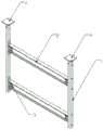
Fig. 1 is a schematic structural diagram of the present invention.
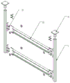
Fig. 2 is an exploded view of the present invention.
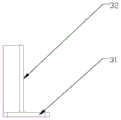
FIG. 3 is a schematic structural view of a profiled bar connector.
FIG. 4 is a front view of the profiled bar coupler.
FIG. 5 is a side view of the connecting member of the section steel.
FIG. 6 is a plan view of the connecting member of the section steel.
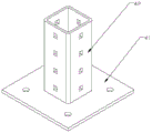
Fig. 7 is a schematic view of the structure of the top connector.
Fig. 8 is a front view of the top attachment.
Fig. 9 is a top view of the top connector.
In the figure: 1. a column; 2. a cross beam; 3. a section steel connecting piece; 31. a first base plate; 32. a connecting plate; 4. a top connector; 41. a second base plate; 42. connecting columns.
Detailed Description
The foregoing and other features, aspects and utilities of the present invention will be apparent from the following detailed description of the embodiments, which is to be read in connection with the accompanying drawings. Directional terms as referred to in the following examples, for example: up, down, left, right, front or rear, etc., are simply directions with reference to the drawings. Therefore, the directional terminology used is for the purpose of describing, but not limiting, the invention, and moreover, like reference numerals designate like elements throughout the embodiments.
The following describes a specific embodiment of the present embodiment with reference to the drawings.
Fig. 1 is a schematic structural diagram of the present invention, and fig. 2 is an explosion diagram of the present invention. Referring to fig. 1 and 2, the assembled heavy-duty support and hanger comprises at least one set of columns 1 and at least one set of beams 2. In this embodiment, an assembled heavy-duty support and hanger includes a set of columns 1 and two sets of beams 2. A group of cross beams 2 are connected with a group of upright posts 1 through section steel connecting pieces 3. The top of the upright post 1 is inserted with a top connecting piece 4.
FIG. 3 is a schematic view showing the structure of a section steel coupling member, FIG. 4 is a front view of the section steel coupling member, FIG. 5 is a side view of the section steel coupling member, and FIG. 6 is a plan view of the section steel coupling member. Referring to fig. 3, 4, 5 and 6, the section steel coupling member 3 includes a first bottom plate 31 and a coupling plate 32. The first bottom plate 31 and the connection plate 32 are perpendicular to each other. The width of the connection plate 32 is smaller than that of the first base plate 31. The first base plate 31 is opened with a plurality of coupling holes. The connecting plate 32 is provided with a clamping groove.
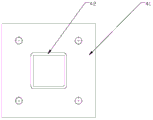
Fig. 7 is a schematic structural view of the top connection member, fig. 8 is a front view of the top connection member, and fig. 9 is a plan view of the top connection member. Referring to fig. 7, 8 and 9, the top connection member 4 includes a second bottom plate 41 and a connection post 42. The connecting column 42 is vertically welded to the second base plate 41. The center line of the connecting column 42 and the center line of the second base plate 41 are on the same straight line.
A plurality of bolt connecting holes are formed in the upright post 1, the cross beam 2, the first bottom plate 31, the connecting plate 32, the second bottom plate 41 and the connecting column 42. The first base plate 31 is bolted to the upright 1. The connecting plate 32 is bolted to the cross beam 2. The connecting column 42 is bolted to the upright 1. The utility model discloses a bolted connection's connected mode, at factory's modularization production, the field installation avoids on-the-spot cutting, moves fire operation etc. has improved the installation effectiveness, has reduced the probability that the incident takes place.
The bolt coupling holes of the first base plate 31 are rectangular in shape. The shapes of the bolt attachment holes of the cross member 2, the connecting plate 32, and the second bottom plate 41 are all circular. The shape of the bolt connecting hole of the upright post 1 and the shape of the bolt connecting hole of the connecting post 42 are both square.
Stand 1 and spliced pole 42 are square pipe, choose for use the side pipe that punches a hole, and rigid connection improves the whole bearing capacity of support, has reduced the probability that the incident takes place, has improved the security of the heavy gallows of assembled. Crossbeam 2 is H shaped steel, chooses for use H shaped steel, has improved crossbeam 2's bearing strength to this security that has improved whole assembled support.
The utility model discloses an installation principle as follows:
the section steel connecting piece 3 is made of thick material by bending, the conditions of complex load and large load of the heavy support and hanger are fully considered, and the requirement of required bearing capacity is met. The difficult problem of the heavy support mounting of assembled is solved to shaped steel connecting piece 3, has avoided the operation of starting a fire. The high adaptation H shaped steel of global design has reduced the influence of complicated load to the heavy gallows of assembled to a certain extent. The material is reasonably selected, the weight required by hoisting is considered, and the safety factor is high.
The top connecting piece 4 is made of thick materials by welding, the strength of the welding line is firm and uniform, and the bearing capacity is high; the problems that the assembled gravity support needs large load and the load is complex are solved; the integral design is symmetrical, so that the damage of the shearing force to the integral hoisting is reduced to a certain extent; the bottom material takes the weight required by hoisting into consideration, and the safety during hoisting is ensured.
The above description is for the purpose of explanation and not limitation of the invention, which is defined in the claims, and any modifications may be made without departing from the basic structure of the invention.
Claims (8)
1. The utility model provides a heavy gallows of assembled which characterized in that: comprises at least one group of upright posts (1) and at least one group of cross beams (2); the group of beams (2) are connected with the group of columns (1) through section steel connecting pieces (3); the section steel connecting piece (3) comprises a first bottom plate (31) and a connecting plate (32); the first bottom plate (31) and the connecting plate (32) are perpendicular to each other; the first bottom plate (31) is provided with a plurality of connecting holes; the connecting plate (32) is provided with a clamping groove; a top connecting piece (4) is inserted into the top of the upright post (1); the top connecting piece (4) comprises a second bottom plate (41) and a connecting column (42); the connecting column (42) is vertically welded on the second bottom plate (41); a plurality of bolt connecting holes are formed in the upright post (1), the cross beam (2), the first bottom plate (31), the connecting plate (32), the second bottom plate (41) and the connecting column (42); the first bottom plate (31) is connected with the upright post (1) through bolts; the connecting plate (32) is connected with the cross beam (2) through bolts; the connecting column (42) is connected with the upright column (1) through a bolt.
2. The fabricated heavy support and hanger of claim 1, wherein: the width of the connecting plate (32) is smaller than that of the first bottom plate (31).
3. The fabricated heavy support and hanger of claim 1, wherein: the center line of the connecting column (42) and the center line of the second bottom plate (41) are on the same straight line.
4. The fabricated heavy support and hanger of claim 1, wherein: the bolt connecting hole of the first bottom plate (31) is rectangular.
5. The fabricated heavy support and hanger of claim 1, wherein: the shape of the bolt connecting hole of the cross beam (2), the shape of the bolt connecting hole of the connecting plate (32) and the shape of the bolt connecting hole of the second bottom plate (41) are circular.
6. The fabricated heavy support and hanger of claim 1, wherein: the shapes of the bolt connecting holes of the upright posts (1) and the bolt connecting holes of the connecting posts (42) are both square.
7. The fabricated heavy support and hanger of claim 1, wherein: the upright post (1) and the connecting post (42) are square tubes.
8. The fabricated heavy support and hanger of claim 1, wherein: the beam (2) is H-shaped steel.
Priority Applications (1)
| Application Number | Priority Date | Filing Date | Title |
|---|---|---|---|
| CN202020181705.9U CN211623897U (en) | 2020-02-18 | 2020-02-18 | Assembled heavy support and hanger |
Applications Claiming Priority (1)
| Application Number | Priority Date | Filing Date | Title |
|---|---|---|---|
| CN202020181705.9U CN211623897U (en) | 2020-02-18 | 2020-02-18 | Assembled heavy support and hanger |
Publications (1)
| Publication Number | Publication Date |
|---|---|
| CN211623897U true CN211623897U (en) | 2020-10-02 |
Family
ID=72619186
Family Applications (1)
| Application Number | Title | Priority Date | Filing Date |
|---|---|---|---|
| CN202020181705.9U Active CN211623897U (en) | 2020-02-18 | 2020-02-18 | Assembled heavy support and hanger |
Country Status (1)
| Country | Link |
|---|---|
| CN (1) | CN211623897U (en) |
-
2020
- 2020-02-18 CN CN202020181705.9U patent/CN211623897U/en active Active
Similar Documents
| Publication | Publication Date | Title |
|---|---|---|
| CN109695295B (en) | Column-beam assembly type integrated variable beam height node and construction method thereof | |
| CN208965708U (en) | Steel structure system and house | |
| CN102561510A (en) | Factory assembled latticed light steel structure and manufacturing method thereof | |
| CN102261043B (en) | Assembled steel pipe upright post system | |
| CN211623897U (en) | Assembled heavy support and hanger | |
| CN113699884A (en) | Rectangular concrete-filled steel tube cable tower adopting prefabricated web plates | |
| CN211871108U (en) | Construction elevator cage convenient to dismantle and install | |
| CN102864746A (en) | Bearing frame for bridge construction | |
| CN202152442U (en) | Assembling type steel tube-vertical post system | |
| CN212865961U (en) | Detachable building foundation pit supporting beam | |
| CN113863506A (en) | Mixed connection node of assembled concrete column and H shaped steel roof beam | |
| CN202913356U (en) | Load-bearing frame for bridge construction | |
| CN114016608A (en) | Assembly type beam-column strong shaft connecting joint and construction method thereof | |
| CN216075601U (en) | Assembled concrete column girder steel hybrid connection node | |
| CN211774629U (en) | Assembled abnormal shape node connecting device | |
| CN215562877U (en) | Foundation supporting device for shear wall or column replacement | |
| CN217734539U (en) | Adjustable assembled suspended ceiling reverse supporting device | |
| CN214303110U (en) | Assembled antidetonation steel construction beam column connected node | |
| CN220375278U (en) | Can have enough to meet need reinforcing bar stock yard support | |
| CN217537298U (en) | Deformed steel structure beam column | |
| CN210067068U (en) | Reinforced concrete column and steel beam connecting joint and building | |
| CN214302258U (en) | Connecting device of assembled steel structure beam column node based on BIM | |
| CN219411777U (en) | Drawer type adjustable steel structure string Liang Diaolan clamping plate | |
| CN216616566U (en) | Steel plate welding cross-column steel structure | |
| CN214614567U (en) | Titanium-nickel memory alloy high-strength bolt steel truss beam column connecting part |
Legal Events
| Date | Code | Title | Description |
|---|---|---|---|
| GR01 | Patent grant | ||
| GR01 | Patent grant | ||
| PE01 | Entry into force of the registration of the contract for pledge of patent right | ||
| PE01 | Entry into force of the registration of the contract for pledge of patent right |
Denomination of utility model: Fabricated heavy support and hanger Effective date of registration: 20210726 Granted publication date: 20201002 Pledgee: Wuxi Taihu Xincheng sub branch of Bank of Jiangsu Co.,Ltd. Pledgor: WUXI HENGTONG METAL FRAMING SYSTEM Co.,Ltd. Registration number: Y2021320010273 |