CN211619165U - Double-inlet and double-outlet bucket elevator - Google Patents
Double-inlet and double-outlet bucket elevator Download PDFInfo
- Publication number
- CN211619165U CN211619165U CN201922301121.0U CN201922301121U CN211619165U CN 211619165 U CN211619165 U CN 211619165U CN 201922301121 U CN201922301121 U CN 201922301121U CN 211619165 U CN211619165 U CN 211619165U
- Authority
- CN
- China
- Prior art keywords
- roller assembly
- double
- section
- conveying belt
- feeding
- Prior art date
- Legal status (The legal status is an assumption and is not a legal conclusion. Google has not performed a legal analysis and makes no representation as to the accuracy of the status listed.)
- Active
Links
Images


Abstract
A double-inlet and double-outlet bucket elevator comprises a bottom section, a middle section, a top section, a driving device, a feeding hopper, a discharging chute, a driving roller assembly, a driven roller assembly, a conveying belt and a feeding hopper, wherein the bottom section, the middle section and the top section are connected together to form an elevator main body, the feeding hopper is arranged on the bottom section, the driving roller assembly and the driven roller assembly are respectively arranged on the top section and the bottom section, the driving roller assembly is connected with the driving device, the conveying belt is arranged on rollers of the driving roller assembly and the driven roller assembly, and the feeding hopper is fixed on the conveying belt, and the elevator is characterized in that the conveying belt is a widened conveying belt, two rows of feeding hoppers are arranged on the conveying belt, a partition plate is arranged between the middle and two rows of feeding hoppers to divide the feeding hopper into two feeding intervals, and a distributor is respectively arranged on the top section corresponding to each row of feeding hoppers, and has the advantages that two materials can, the purpose of simultaneously improving different materials by double inlet and double outlet is realized, the working efficiency is improved, the occupied area is not increased, and the use in a production line is facilitated.
Description
Technical Field
The utility model belongs to a material conveyor, in particular to double-in double-out formula bucket elevator.
Background
The bucket elevator is widely applied to industrial production, can lift general powdery, granular and blocky materials, and has the advantages of large conveying capacity, small driving power, high lifting height, stable operation, convenient maintenance and low use cost. The existing bucket elevator mainly comprises a bottom section, a middle section, a top section, a driving device, a charging hopper, a discharging scraper-trough conveyer, a driving roller assembly, a driven roller assembly, a conveying belt, a feeding hopper and the like. The middle section can be one section or a plurality of sections, the bottom section, the middle section and the top section are connected together to form a main body of the elevator, the charging hopper is arranged on the bottom section, the discharging chute is arranged on the top section, the driving roller assembly and the driven roller assembly are respectively arranged on the top section and the bottom section, the driving roller assembly is connected with the driving device and driven by the driving device to rotate, the conveying belt is arranged on the rollers of the driving roller assembly and the driven roller assembly, and the feeding hopper is fixed on the conveying belt. The bucket elevator has the main problems that the bucket elevator is low in working efficiency, only one material can be lifted, and the discharging direction is limited because the connecting end at the upper part of the discharging chute is rectangular, so that the bucket elevator is not suitable for being used in a complex production line.
Disclosure of Invention
The to-be-solved technical problem of the utility model is, overcome the work efficiency that current bucket elevator exists low, promote the material singleness, be not convenient for the problem of combined use in the production line, provide a work efficiency height, can promote different materials simultaneously, be convenient for the nimble two-in two-out formula bucket elevator who uses in the production line.
The utility model comprises a bottom section, a middle section, a top section, a driving device, a feeding hopper, a discharging scraper-trough conveyer, a driving roller component, a driven roller component, a conveyer belt and a feeding hopper, wherein the bottom section, the middle section and the top section are connected together to form a main body of the elevator, the feeding hopper is arranged on the bottom section, the driving roller component and the driven roller component are respectively arranged on the top section and the bottom section, the driving roller component is connected with the driving device and driven to rotate by the driving device, the conveyer belt is arranged on a roller of the driving roller component and the driven roller component, the feeding hopper is fixed on the conveyer belt, the special part is that the conveyer belt is a widened conveyer belt, two rows of feeding hoppers are arranged on the conveyer belt so as to simultaneously convey two different materials, a partition plate is arranged between the feeding hoppers in the feeding hopper and the two rows of feeding hoppers, a distributor is respectively arranged on the top section corresponding to each row, the materials conveyed by the two rows of feeding hoppers are separated.
The outlet end of the distributor is connected with the discharging scraper-trough conveyer by a circular flange so as to adjust the discharging direction of the discharging scraper-trough conveyer.
And a partition plate is arranged between the middle and two rows of feeding hoppers in the top section, so that materials conveyed by the two rows of feeding hoppers are prevented from being mixed together.
The utility model has the advantages that:
1. the partition plate is arranged in the feeding hopper, the feeding hopper is divided into two feeding intervals, the widened conveying belt is arranged on the rollers of the driving roller assembly and the driven roller assembly, the two rows of feeding hoppers are arranged on the conveying belt, one conveying system can convey two materials simultaneously, the purpose that different materials are simultaneously lifted by one set of conveying system is achieved, the working efficiency is improved, and the occupied area is not increased.
2. Install the tripper on the top section, the material that carries two rows of feeding hoppers separately to be connected with the swift current son of unloading with circular flange, through the butt joint of bolt hole on the flange, the ejection of compact direction of the swift current son of unloading can be very convenient in 270 degrees within ranges adjustment, can realize that the production line promotes simultaneously, just carries the requirement of different positions to different materials, is convenient for use in the production line.
Drawings
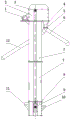
Fig. 1 is a schematic structural diagram of the present invention;
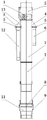
FIG. 2 is a left side view of FIG. 1;
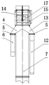
FIG. 3 is a schematic view of the internal structure of FIG. 2;
FIG. 4 is an enlarged view of portion A of FIG. 2;
FIG. 5 is a right side view of FIG. 1;
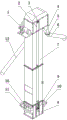
fig. 6 is a perspective view of the present invention.
Detailed Description
As shown in the attached drawings, the utility model comprises a bottom section 8, a middle section 7, a top section 2, a driving device 1, loading hoppers 10 and 11, discharging chutes 6 and 12, a driving roller assembly 3, a driven roller assembly 9, a conveying belt 14 and a feeding hopper 15; the middle section 7 has two sections, and the bottom section 8, the middle section 7 and the top section 2 are connected together by bolts to form a main body of the elevator; the charging hoppers 10 and 11 are arranged on the bottom section 8 and are respectively positioned at two sides of the bottom section 8 so as to be convenient for charging at two sides of the elevator; the driving roller assembly 3 comprises a roller, a bearing and a fixed seat, the driving roller assembly 3 is arranged on the top section 2 through the bearing and the fixed seat, the driven roller assembly 9 comprises a roller, a bearing and a fixed seat, and the driven roller assembly 9 is arranged on the bottom section 8 through the bearing and the fixed seat; the driving device 1 comprises a motor, a transmission belt and a belt pulley, the driving roller component 3 is connected with the driving device 1 through the belt pulley and the transmission belt and is driven by the driving device 1 to rotate; the conveyer belt 14 is arranged on the rollers of the driving roller assembly 3 and the driven roller assembly 9; a plurality of feeding hoppers 15 are respectively fixed on the conveying belt 14; the conveyer belt 14 is a widened conveyer belt, two rows of feeding hoppers 15 are arranged on the conveyer belt 14 so as to be convenient for simultaneously conveying two different materials, a partition plate 16 is arranged between the feeding hoppers 10 and 11 and the two rows of feeding hoppers 15, the partition plate 16 is positioned at the outer side of the conveyer belt 14, and the feeding hoppers 10 and 11 are divided into two feeding sections so as to be convenient for adding different materials into the elevator; the rollers on the bottom section 8, the middle section 7, the top section 2, the driving roller assembly 3 and the driven roller assembly 9 are properly widened, so that a widened conveying belt 14 can be placed conveniently; a partition plate 17 is arranged between the middle section 2 and the two rows of feeding hoppers 15, and the partition plate 17 is positioned at the outer side of the conveying belt 14, so that the materials conveyed by the two rows of feeding hoppers 15 are prevented from being mixed together during material pouring; the top section 2 is respectively provided with a distributor 4 and a distributor 13 corresponding to each row of feeding hoppers 15, materials conveyed by the two rows of feeding hoppers 15 are separated, the distributors 4 and the distributors 13 are separated towards two sides and extend out of two sides of the middle section 7, the outlet ends of the distributors 4 and 13 are connected with the discharging chutes 6 and 12 through the circular flanges 5, namely, the connecting ends of the discharging chutes 6 and 12 are also the circular flanges 5 so as to be convenient to connect, and meanwhile, bolt holes on the circular flanges 5 are uniformly distributed on the circumference, so that the discharging directions of the discharging chutes 6 and 12 can be changed by changing the relative rotation angle between the two circular flanges 5 during assembly, the discharging directions of the discharging chutes 6 and 12 can be adjusted within the range of 270 degrees, and the feeding to different directions and positions in a production line is convenient.
Claims (3)
1. A double-inlet and double-outlet bucket elevator comprises a bottom section, a middle section, a top section, a driving device, a feeding hopper, a discharging chute, a driving roller assembly, a driven roller assembly, a conveying belt and a feeding hopper, wherein the bottom section, the middle section and the top section are connected together to form an elevator main body, the feeding hopper is arranged on the bottom section, the driving roller assembly and the driven roller assembly are respectively arranged on the top section and the bottom section, the driving roller assembly is connected with the driving device, the conveying belt is arranged on rollers of the driving roller assembly and the driven roller assembly, and the feeding hopper is fixed on the conveying belt.
2. The double-in double-out bucket elevator as claimed in claim 1, wherein the outlet end of the distributor is connected to the discharge chute by means of a circular flange.
3. The double-in double-out bucket elevator as claimed in claim 1, wherein a partition plate is installed between the top section and the two rows of the upper hoppers.
Priority Applications (1)
| Application Number | Priority Date | Filing Date | Title |
|---|---|---|---|
| CN201922301121.0U CN211619165U (en) | 2019-12-20 | 2019-12-20 | Double-inlet and double-outlet bucket elevator |
Applications Claiming Priority (1)
| Application Number | Priority Date | Filing Date | Title |
|---|---|---|---|
| CN201922301121.0U CN211619165U (en) | 2019-12-20 | 2019-12-20 | Double-inlet and double-outlet bucket elevator |
Publications (1)
| Publication Number | Publication Date |
|---|---|
| CN211619165U true CN211619165U (en) | 2020-10-02 |
Family
ID=72630448
Family Applications (1)
| Application Number | Title | Priority Date | Filing Date |
|---|---|---|---|
| CN201922301121.0U Active CN211619165U (en) | 2019-12-20 | 2019-12-20 | Double-inlet and double-outlet bucket elevator |
Country Status (1)
| Country | Link |
|---|---|
| CN (1) | CN211619165U (en) |
Cited By (1)
| Publication number | Priority date | Publication date | Assignee | Title |
|---|---|---|---|---|
| CN112141622A (en) * | 2020-10-12 | 2020-12-29 | 淮北良信矿山机器有限公司 | Bucket elevator outer support |
-
2019
- 2019-12-20 CN CN201922301121.0U patent/CN211619165U/en active Active
Cited By (1)
| Publication number | Priority date | Publication date | Assignee | Title |
|---|---|---|---|---|
| CN112141622A (en) * | 2020-10-12 | 2020-12-29 | 淮北良信矿山机器有限公司 | Bucket elevator outer support |
Similar Documents
| Publication | Publication Date | Title |
|---|---|---|
| CN211619165U (en) | Double-inlet and double-outlet bucket elevator | |
| CN213949747U (en) | Free type conveying roller | |
| CN213706751U (en) | Vertical material lifting equipment | |
| CN210437894U (en) | Heavy-load plate chain bucket elevator | |
| CN210312094U (en) | Bucket elevator for energetic materials with stable operation | |
| CN212049266U (en) | Material conveying unit | |
| CN212686783U (en) | Belt conveying system for multi-point discharging | |
| CN209814944U (en) | Bulk cargo lifting machine | |
| CN209854796U (en) | Crushing hopper and excavator with same | |
| CN204777502U (en) | Raw materials conveyer | |
| CN209411329U (en) | A kind of bin discharger for Bulk foodstuff dock vertical silo | |
| CN109570035B (en) | Working method of conveying and sorting device | |
| CN105836485B (en) | Circular coal yard unloader | |
| CN205367165U (en) | Transfer chain suitable for grit is transported and is stacked | |
| CN106731943B (en) | Fertilizer distributor | |
| CN215515385U (en) | Arc bottom bucket type powder elevator | |
| CN111232617A (en) | Belt conveying system for multi-point discharging | |
| CN203714632U (en) | Tower type belt conveyor capable of being rotated by 360 degrees | |
| CN214877629U (en) | Material lifting and conveying device | |
| CN215853369U (en) | Continuous non-crushing elevator | |
| CN215477723U (en) | Z-shaped elevator | |
| CN205366937U (en) | Transfer chain that peripheral material is stacked to centre | |
| CN215917281U (en) | Waste incineration fly ash homogenizing device | |
| CN212314987U (en) | Ship unloaders and portable head funnel device thereof | |
| CN209506815U (en) | BGC template chain scraper conveyer |
Legal Events
| Date | Code | Title | Description |
|---|---|---|---|
| GR01 | Patent grant | ||
| GR01 | Patent grant |