CN211614371U - Radial drill with safeguard function - Google Patents
Radial drill with safeguard function Download PDFInfo
- Publication number
- CN211614371U CN211614371U CN202020087041.XU CN202020087041U CN211614371U CN 211614371 U CN211614371 U CN 211614371U CN 202020087041 U CN202020087041 U CN 202020087041U CN 211614371 U CN211614371 U CN 211614371U
- Authority
- CN
- China
- Prior art keywords
- baffle
- plate
- joint
- radial drill
- safeguard function
- Prior art date
- Legal status (The legal status is an assumption and is not a legal conclusion. Google has not performed a legal analysis and makes no representation as to the accuracy of the status listed.)
- Expired - Fee Related
Links
- 230000007704 transition Effects 0.000 claims description 9
- 230000000694 effects Effects 0.000 abstract description 3
- 238000005553 drilling Methods 0.000 description 20
- 238000004140 cleaning Methods 0.000 description 8
- 238000010586 diagram Methods 0.000 description 4
- 230000000903 blocking effect Effects 0.000 description 3
- 238000003754 machining Methods 0.000 description 3
- 238000000034 method Methods 0.000 description 2
- 230000004888 barrier function Effects 0.000 description 1
- 238000010923 batch production Methods 0.000 description 1
- 239000013013 elastic material Substances 0.000 description 1
- 238000010030 laminating Methods 0.000 description 1
- 238000010079 rubber tapping Methods 0.000 description 1
- 238000007790 scraping Methods 0.000 description 1
- 238000000926 separation method Methods 0.000 description 1
Images


Landscapes
- Auxiliary Devices For Machine Tools (AREA)
Abstract
The utility model relates to a radial drill with safeguard function, it relates to radial drill's technical field, including the plate body that is equipped with the spout, the up end of plate body is equipped with the rectangular hole, and sliding connection has the baffle in the spout, and spout and fixedly connected with lifter are stretched out from the rectangular hole in the upper end of baffle, are connected with the locating part that restriction plate body and baffle break away from on the baffle. The utility model discloses have the effect that prevents that the piece from splashing on one's body the staff.
Description
Technical Field
The utility model belongs to the technical field of radial drill's technique and specifically relates to a radial drill with safeguard function is related to.
Background
The drilling machines are classified according to purposes and structures, and can be divided into upright drilling machines, bench drilling machines, multi-hole drilling machines, radial drilling machines, other special drilling machines and the like. Among various drilling machines, the radial drilling machine is convenient and flexible to operate, wide in application range and typical, is particularly suitable for hole machining of porous large parts in single piece or batch production, is a common machine tool in common machining workshops, and can be used for machining in various forms such as drilling, reaming, tapping, end face scraping and the like.
The current chinese patent with publication number CN209288329U discloses a radial drill with safeguard function, including the base, set up stand on the base, rotate the rocking arm of connecting in the stand, slide and set up the headstock on the rocking arm, the base is provided with inside hollow workstation in the headstock below, the spout has been seted up to the up end of workstation, be provided with the baffle in the spout, be provided with the lifting unit that control baffle stretches out in the spout from the workstation. When the radial drilling machine drills, the lifting assembly is controlled to enable the baffle to slide out of the sliding groove, and then chips thrown out in the drilling process are blocked.
Also provide a radial drill now, it also can prevent that the piece that radial drill during operation produced from splashing on the staff, causes the damage to the staff.
SUMMERY OF THE UTILITY MODEL
Not enough to prior art exists, the utility model aims at providing a radial drill with safeguard function, it has the effect that prevents that the piece from splashing on one's body the staff.
The above object of the present invention is achieved by the following technical solutions:
the utility model provides a radial drill with safeguard function, is including the plate body that is equipped with the spout, and the up end of plate body is equipped with the rectangular hole, and sliding connection has the baffle in the spout, and spout and fixedly connected with lifter are stretched out from the rectangular hole in the upper end of baffle, are connected with the locating part that restriction plate body and baffle break away from on the baffle.
By adopting the technical scheme, the length direction of the strip hole is narrower than that of the sliding chute, and the roller cannot be separated from the strip hole into the plate body; when the radial drilling machine works, the lifting piece can be started firstly, so that the lifting piece drives the baffle to move upwards along the sliding groove, when the limiting piece butts against the upper end face of the sliding groove, the baffle rises to the highest position, the air cylinder is closed at the moment, and then the radial drilling machine is started; the baffle can shelter from the piece that radial drill during operation produced towards the staff and splash this moment, prevents that the piece from splashing on the staff.
The present invention may be further configured in a preferred embodiment as: the locating parts are rollers which are arranged on two side faces of the baffle and are attached to the side walls of the sliding grooves to rotate.
Through adopting above-mentioned technical scheme, when baffle and plate body take place relative movement, the lateral wall of gyro wheel laminating spout rotates, resistance when reducing the baffle motion makes the baffle take place relative movement with the plate body more easily.
The present invention may be further configured in a preferred embodiment as: the upper surface of baffle is equipped with the joint groove, the one side that the workstation was kept away from to the baffle upper end articulates there is the rotor plate, the one end and the joint groove joint of rotor plate.
Through adopting above-mentioned technical scheme, the rotor plate can increase and shelter from the area that the piece splashes, and further place the piece and splash to the staff on one's body.
The present invention may be further configured in a preferred embodiment as: when one end of the rotating plate is clamped with the clamping groove, the rotating plate is fixedly connected with the baffle through the locking mechanism.
Through adopting above-mentioned technical scheme, when rotor plate and joint groove joint, rotor plate and baffle locking when starting locking mechanism, locking mechanism can strengthen being connected of baffle and rotor plate this moment.
The present invention may be further configured in a preferred embodiment as: the locking mechanism comprises a clamping plate, two elastic clamping blocks are arranged on one side face of the clamping plate, a first clamping hole is formed in the baffle, a second clamping hole is formed in the rotating plate, and the two clamping blocks are clamped with the first clamping hole and the second clamping hole respectively.
Through adopting above-mentioned technical scheme, after rotatory rotor plate made rotor plate and joint groove joint, two joint pieces on making the joint board again respectively with first joint hole and second joint hole joint, the joint board has strengthened being connected of rotor plate and baffle this moment.
The present invention may be further configured in a preferred embodiment as: and a third clamping and connecting hole is formed in the rotating plate.
Through adopting above-mentioned technical scheme, when the rotor plate is packed up to needs, pull out the joint board and make two joint pieces break away from first joint hole and second joint hole respectively, rotatory rotor plate makes the side of rotor plate be close the side attached to the baffle afterwards, makes two joint pieces on the joint board respectively with first joint hole and third joint hole joint afterwards.
The present invention may be further configured in a preferred embodiment as: a door body is hinged to one side face of the plate body and is locked with the plate body through a locking piece.
By adopting the technical scheme, when the swing arm drilling machine works, a part of scraps can enter the sliding groove of the plate body along the strip hole, and a side surface of the plate body is hinged with the door body for cleaning conveniently; when the cleaning is needed, only the door body needs to be opened for cleaning.
The present invention may be further configured in a preferred embodiment as: the locking piece comprises a transition plate, the transition plate is rotatably connected with one side face of the door body, and the transition plate is fixedly connected with the plate body through bolts.
Through adopting above-mentioned technical scheme, when the door body clearance plate body is inside to needs are opened, not hard up bolt makes it break away from cab apron and plate body, open the door body afterwards can.
The present invention may be further configured in a preferred embodiment as: the lifting piece is a cylinder.
Through adopting above-mentioned technical scheme, the cylinder drives the baffle and rises or descends along the spout.
To sum up, the utility model discloses a following at least one useful technological effect:
1. the baffle can shield the scraps generated by the radial drilling machine during working from splashing to the workers, and the scraps are prevented from splashing to the workers;
2. the rotating plate can increase the area for shielding the splash of the scraps, and further place the splashed scraps on the body of a worker;
3. when the swing arm drilling machine works, a part of scraps can enter the sliding groove of the plate body along the strip hole, and a door body is hinged to one side surface of the plate body for cleaning convenience; when the cleaning is needed, only the door body needs to be opened for cleaning.
Drawings
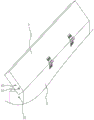
FIG. 1 is a schematic diagram showing the overall structure of the embodiment;
FIG. 2 is a schematic view of a chute structure according to an embodiment;
FIG. 3 is a diagram illustrating a structure of a snap groove according to an embodiment;
FIG. 4 is a schematic structural diagram illustrating the engagement between the rotating plate and the engaging groove according to the embodiment;
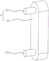
FIG. 5 is a schematic structural diagram of an embodiment embodying a locking mechanism.
In the figure, 1, a base; 11. a column; 12. a rocker arm; 13. a main spindle box; 14. a work table; 2. a plate body; 21. mounting a plate; 22. a chute; 23. a strip hole; 3. a baffle plate; 31. a connecting rod; 32. a cylinder; 33. a roller; 34. a clamping groove; 35. a first clamping hole; 4. a rotating plate; 41. a second clamping hole; 42. a third bayonet hole; 5. a locking mechanism; 51. a clamping and connecting plate; 511. a clamping block; 6. a door body; 7. a transition plate.
Detailed Description
The present invention will be described in further detail with reference to the accompanying drawings.
As fig. 1, for the utility model discloses a radial drill with safeguard function, including base 1, the 1 upper surface of base is provided with stand 11, and the last swivelling joint of stand 11 has rocking arm 12, and sliding connection has headstock 13 on rocking arm 12, fixedly connected with workstation 14 on the base 1, and workstation 14 is located headstock 13's below.
As shown in fig. 1, the end, close to the staff, of the upper end surface of the base 1 is detachably connected with the plate body 2 arranged in the vertical direction, a sliding groove 22 (shown in fig. 2) is formed in the plate body 2, the surface of the plate body 2 is fixedly connected with a mounting plate 21, and the mounting plate 21 is connected with the base 1 through a plurality of bolts.
As shown in fig. 1 and 2, the upper end surface of the plate body 2 is provided with a long hole 23, the sliding groove 22 is slidably connected with the baffle plate 3, and the upper end of the baffle plate 3 extends out of the long hole 23 to the inside of the plate body 2. Two relative sides that baffle 3 stretches out plate body 2 outside are fixedly connected with connecting rod 31 respectively, and connecting rod 31 horizontal direction sets up, and the lower fixed surface of connecting rod 31 is connected with the piston rod of cylinder 32, and the piston rod is vertical upwards to be set up. The plate body 2 and the part of the baffle plate 3 extending out of the baffle plate 3 are not higher than the workbench 14, so that the influence of the part of the plate body 2 and the part of the baffle plate 3 extending out of the baffle plate 3 on the placement of a workpiece on the workbench 14 is prevented.
When the radial arm 12 drilling machine works, the two air cylinders 32 can be simultaneously started, so that the piston rods of the air cylinders 32 push the connecting rod 31 and the baffle plate 3 to move upwards to block chips splashed to workers.
As shown in fig. 2, in order to limit the separation of the blocking plate 3 from the plate body 2, rollers 33 are rotatably connected to both sides of the blocking plate 3, the rollers 33 are located at one end of the blocking plate 3 close to the mounting plate 21 (see fig. 1), the length direction of the elongated hole 23 is narrower than that of the sliding slot 22, and the rollers 33 cannot be separated from the elongated hole 23 into the plate body 2. When the shutter 3 moves upward until the roller 33 abuts against the upper end face of the chute 22, the shutter 3 rises to the uppermost position.
When the baffle 3 and the plate body 2 move relatively, the roller 33 is attached to the side wall of the sliding groove 22 to rotate, so that the resistance of the baffle 3 during movement is reduced, and the baffle 3 and the plate body 2 move relatively more easily.
Referring to fig. 1 and 2, when the swing arm drilling machine works, a part of chippings may enter the sliding groove 22 of the plate body 2 along the strip hole 23, and for convenience of cleaning, one side surface of the plate body 2 is hinged with the door body 6. When the debris in the chute 22 needs to be cleaned, the door body 6 is opened for cleaning. A locking piece is fixed on one side surface of the door body 6 far away from the hinged end of the door body 2 and the door body 6, and the door body 6 is locked with the door body 2 by the locking piece.
The locking piece comprises a transition plate 7 which is rotatably connected with the door body 6 and can rotate in the vertical direction, and one end, far away from the door body 6, of the transition plate 7 is fixedly connected with the plate body 2 through bolts.
As shown in figure 3, in order to increase the area for shielding the splash of the scraps, the upper end of the baffle plate 3, which is far away from the workbench 14, is hinged with a rotating plate 4. The upper surface of the baffle 3 is provided with a clamping groove 34. The rotating plate 4 is rotated to allow one corner of the rotating plate 4 to be engaged with the engaging groove 34, as shown in fig. 4, and the rotating plate 4 is tilted toward the worktable 14 (see fig. 1).
As shown in fig. 4 and 5, in order to strengthen the connection between the baffle 3 and the rotating plate 4, the rotating plate 4 and the baffle 3 are fixedly connected through a locking mechanism 5. The locking mechanism 5 comprises a clamping plate 51, two clamping blocks 511 made of elastic materials are arranged on one side face of the clamping plate 51, first clamping holes 35 are respectively formed in two opposite side faces of the baffle 3, second clamping holes 41 are formed in two opposite side faces of the rotating plate 4, and the two clamping blocks 511 on the clamping plate 51 are respectively clamped with the first clamping holes 35 and the second clamping holes 41.
As shown in fig. 3 and 5, when the radial drill press stops operating, the pivotal plate 4 needs to be retracted. The chucking plate 51 is pulled out to make the chucking plate 51 away from the rotating plate 4, and then the rotating plate 4 is rotated to make the rotating plate 4 adhere to one side of the barrier 3. The two side faces of the rotating plate 4 provided with the second clamping holes 41 are also provided with third clamping holes 42. When the baffle 3 in this state needs to be locked with the rotating plate 4, the two clamping blocks 511 on the clamping plate 51 are respectively clamped with the first clamping hole 35 and the third clamping hole 42.
The implementation principle of the embodiment is as follows: firstly, a workpiece is placed on the workbench 14, before the radial arm 12 drilling machine starts to work, the air cylinder 32 is started, the air cylinder 32 drives the baffle 3 to move upwards, and when the roller 33 abuts against the upper end face of the sliding chute 22, the air cylinder 32 is closed. Then, the clamping plate 51 is pulled out to separate the two clamping blocks 511 from the first clamping hole 35 and the third clamping hole 42, the rotating plate 4 is rotated to clamp the rotating plate 4 with the clamping groove 34, and then the two clamping blocks 511 of the clamping plate 51 are clamped with the first clamping hole 35 and the second clamping hole 41. The radial drill 12 may finally be activated.
After the drilling machine work of the rocker arm 12 is completed, two clamping blocks 511 are respectively separated from the first clamping hole 35 and the second clamping hole 41, the rotating plate 4 is rotated again to enable the rotating plate 4 and the baffle 3 to be attached to one surface far away from the workbench 14, then the air cylinder 32 is started, the baffle 3 slides downwards to the bottom of the roller 33 abutting against the sliding groove 22, and then the air cylinder 32 is closed. Finally, the workpiece at the work table 14 is removed.
The embodiment of this specific implementation mode is the preferred embodiment of the present invention, not limit according to this the utility model discloses a protection scope, so: all equivalent changes made according to the structure, shape and principle of the utility model are covered within the protection scope of the utility model.
Claims (9)
1. The utility model provides a radial drill with safeguard function which characterized in that: including plate body (2) that is equipped with spout (22), the up end of plate body (2) is equipped with rectangular hole (23), and sliding connection has baffle (3) in spout (22), and spout (22) and fixedly connected with lifter are stretched out from rectangular hole (23) in the upper end of baffle (3), are connected with the locating part that restriction plate body (2) and baffle (3) break away from on baffle (3).
2. The radial drill press with a safeguard function according to claim 1, characterized in that: the limiting pieces are rollers (33), and the rollers (33) are arranged on two side faces of the baffle (3) and are attached to the side walls of the sliding grooves (22) to rotate.
3. The radial drill press with a safeguard function according to claim 1, characterized in that: the upper surface of baffle (3) is equipped with joint groove (34), the one side that workstation (14) were kept away from to baffle (3) upper end articulates there is rotor plate (4), the one end and the joint groove (34) joint of rotor plate (4).
4. The radial drill press with a safeguard function according to claim 3, characterized in that: when one end of the rotating plate (4) is clamped with the clamping groove (34), the rotating plate (4) is fixedly connected with the baffle (3) through the locking mechanism (5).
5. The radial drill press with a safeguard function according to claim 4, characterized in that: locking mechanism (5) are equipped with two elasticity joint piece (511) including joint board (51), joint board (51) one side, be equipped with first joint hole (35) on baffle (3), be equipped with second joint hole (41) on rotor plate (4), two joint pieces (511) respectively with first joint hole (35) and second joint hole (41) joint.
6. The radial drill press with a safeguard function according to claim 4, characterized in that: and a third clamping and connecting hole (42) is formed in the rotating plate (4).
7. The radial drill press with a safeguard function according to claim 1, characterized in that: a side face of the plate body (2) is hinged with a door body (6), and the door body (6) is locked with the plate body (2) through a locking piece.
8. The radial drill press with a safeguard function according to claim 7, characterized in that: the locking piece comprises a transition plate (7), the transition plate (7) is rotatably connected with one side face of the door body (6), and the transition plate (7) is fixedly connected with the plate body (2) through bolts.
9. The radial drill press with a safeguard function according to claim 1, characterized in that: the lifting piece is an air cylinder (32).
Priority Applications (1)
| Application Number | Priority Date | Filing Date | Title |
|---|---|---|---|
| CN202020087041.XU CN211614371U (en) | 2020-01-15 | 2020-01-15 | Radial drill with safeguard function |
Applications Claiming Priority (1)
| Application Number | Priority Date | Filing Date | Title |
|---|---|---|---|
| CN202020087041.XU CN211614371U (en) | 2020-01-15 | 2020-01-15 | Radial drill with safeguard function |
Publications (1)
| Publication Number | Publication Date |
|---|---|
| CN211614371U true CN211614371U (en) | 2020-10-02 |
Family
ID=72638001
Family Applications (1)
| Application Number | Title | Priority Date | Filing Date |
|---|---|---|---|
| CN202020087041.XU Expired - Fee Related CN211614371U (en) | 2020-01-15 | 2020-01-15 | Radial drill with safeguard function |
Country Status (1)
| Country | Link |
|---|---|
| CN (1) | CN211614371U (en) |
Cited By (4)
| Publication number | Priority date | Publication date | Assignee | Title |
|---|---|---|---|---|
| CN113210659A (en) * | 2021-05-02 | 2021-08-06 | 许华 | Drilling equipment is used in processing of metal parts |
| CN113579300A (en) * | 2021-08-09 | 2021-11-02 | 浙江互利模具有限公司 | Drilling equipment is used in die casting die production |
| CN113618107A (en) * | 2021-08-23 | 2021-11-09 | 杭州兴海铸造有限公司 | Radial drilling machine |
| CN117733615A (en) * | 2024-02-21 | 2024-03-22 | 常州创胜特尔数控机床设备有限公司 | Positioning and clamping mechanism for machine tool and working method |
-
2020
- 2020-01-15 CN CN202020087041.XU patent/CN211614371U/en not_active Expired - Fee Related
Cited By (5)
| Publication number | Priority date | Publication date | Assignee | Title |
|---|---|---|---|---|
| CN113210659A (en) * | 2021-05-02 | 2021-08-06 | 许华 | Drilling equipment is used in processing of metal parts |
| CN113579300A (en) * | 2021-08-09 | 2021-11-02 | 浙江互利模具有限公司 | Drilling equipment is used in die casting die production |
| CN113618107A (en) * | 2021-08-23 | 2021-11-09 | 杭州兴海铸造有限公司 | Radial drilling machine |
| CN117733615A (en) * | 2024-02-21 | 2024-03-22 | 常州创胜特尔数控机床设备有限公司 | Positioning and clamping mechanism for machine tool and working method |
| CN117733615B (en) * | 2024-02-21 | 2024-04-19 | 常州创胜特尔数控机床设备有限公司 | Positioning and clamping mechanism for machine tool and working method |
Similar Documents
| Publication | Publication Date | Title |
|---|---|---|
| CN211614371U (en) | Radial drill with safeguard function | |
| CN110496997B (en) | A protection type drilling machine that is used for having of mould production clearance function | |
| CN219379031U (en) | Automatic sputter-proof drilling machine of collection waste material | |
| CN210967059U (en) | Multi-station drilling machine | |
| CN218284592U (en) | A novel drilling equipment for machining of mechanical equipment accessory | |
| CN216065619U (en) | Multi-spindle drilling machine capable of recycling waste materials | |
| CN217343634U (en) | Drilling machine tool for mechanical design and machining | |
| CN215033753U (en) | Multifunctional radial drilling machine | |
| CN214393427U (en) | Drilling machine convenient to clean | |
| CN209792835U (en) | contour cutting machine with automatic cleaning function | |
| CN113664255A (en) | Deep hole machining device of deep hole drilling and boring machine and using method thereof | |
| CN208575587U (en) | A kind of building sheet structure perforating device | |
| CN208391633U (en) | Steel drilling machine | |
| CN219684042U (en) | Clamping assembly of workbench of multi-spindle drilling machine | |
| CN112264641A (en) | Multifunctional drilling machine with track sputtering protection structure for machining | |
| CN216502443U (en) | Radial drilling machine capable of collecting waste materials | |
| CN221184770U (en) | Table type drilling machine | |
| CN212886511U (en) | Protection device of boring machine | |
| CN219292782U (en) | Drilling device for mechanical parts | |
| CN220073326U (en) | Double-shaft horizontal boring machine | |
| CN218362249U (en) | Positioning mechanism of shaft sleeve inner wall blind hole machining lathe | |
| CN220178242U (en) | Protective bench drill | |
| CN216505705U (en) | Plank drilling equipment for building engineering | |
| CN218694022U (en) | Radial drill with residue clearance function | |
| CN217474909U (en) | Deep hole numerical control drilling machine |
Legal Events
| Date | Code | Title | Description |
|---|---|---|---|
| GR01 | Patent grant | ||
| GR01 | Patent grant | ||
| CF01 | Termination of patent right due to non-payment of annual fee |
Granted publication date: 20201002 |
|
| CF01 | Termination of patent right due to non-payment of annual fee |