CN2116141U - Pipe joint - Google Patents
Pipe joint Download PDFInfo
- Publication number
- CN2116141U CN2116141U CN 90206760 CN90206760U CN2116141U CN 2116141 U CN2116141 U CN 2116141U CN 90206760 CN90206760 CN 90206760 CN 90206760 U CN90206760 U CN 90206760U CN 2116141 U CN2116141 U CN 2116141U
- Authority
- CN
- China
- Prior art keywords
- joint
- pipe joint
- screw thread
- diameter
- thread
- Prior art date
- Legal status (The legal status is an assumption and is not a legal conclusion. Google has not performed a legal analysis and makes no representation as to the accuracy of the status listed.)
- Granted
Links
Images


Landscapes
- Joints With Sleeves (AREA)
- Joints With Pressure Members (AREA)
Abstract
The utility model discloses a pipe joint for a connecting line, belonging to auxiliary members for pipe lines. The pipe joint is composed of a pipe joint, a sealing washer, a thread clamping ring and a connecting nut. One end of the external wall of the joint is made into a tetragonal shape or a hexagonal shape, the other end is provided with a left hand outer screw thread, and the inner side is lathed with an inner screw thread of a definite length. The both sides of the inner screw are lathed into a hollow whose diameter is a little larger than the external diameter of the connected pipe. The utility model has the advantages of good sealing property, high pressure resistance, quick connection after the end of the connected pipe is screwed with a screw thread, simple structure and low cost. The utility model is combined with a valve, etc. to form components, improving the performance and reducing total manufacturing cost further.
Description
The utility model belongs to a kind of union of connecting pipeline.
The union that the connection of pipeline is generally adopted at present is made up of coupling nut, two joints and seal washer.Wherein the effect of seal washer is the slit between two joints of sealing, and the sealing of two joints and tube head connecting thread takes to twine fiber crops, japanning on the tube head outside thread method.This union exists time-consuming when reality is used and bears shortcoming such as pressure difference.Recently the model utility " quick coupling " (CN 87 210685 U) that proposes exists also that to bear pressure low, complex structure, problems such as manufacture cost height.
The purpose of this utility model provide a kind of connect and can interrogate fast connecting pipeline after opening screw thread on two tube heads, not only easy to use, also can improve the movable pipe joint that bears pressure, simple in structure and low cost of manufacture.
The purpose of this utility model is finished with the following methods.The joint of internal thread and sinistral external thread is arranged being processed with the car of screwing on the externally threaded tube head, make the tube head end face concordant with joint internal thread end face, again seal washer is abutted against the tube head end face, the externally threaded tube head of being processed with of another pipe earlier the get on the bus screw thread collar of screwing on behind the coupling nut of levogyrate inner thread of cover make the tube head end face give prominence to screw thread collar suitable length, at last coupling nut is tightened on the sinistral external thread of joint, it is close mutually to cause joint and screw thread collar to drive connected two pipes respectively, make seal washer be subjected to the extruding of two tube head end faces and be out of shape, thereby realize the connection and the sealing of pipeline from both sides.
Further described below in conjunction with accompanying drawing.
Fig. 1 is a citation form of the present utility model.
Fig. 2 is embodiment's of the present utility model 1 mounting structure figure.
Fig. 3 is embodiment's of the present utility model 2 mounting structure figure.
Fig. 4 is embodiment's of the present utility model 3 mounting structure figure.
The utility model is according to structure shown in Figure 1, and a kind of movable pipe joint is by joint (1), seal washer (2) , screw thread collar (3) and coupling nut (4) form. One end of the outer wall of joint (1) is processed into square or hexagon, other end processing sinistral external thread and in it sidecar the internal thread of certain-length is arranged, two sidecars of internal thread become neutral gear, its slightly larger in diameter is in the external diameter that is connected pipe. Seal washer (2) is the closed annular body of square-section. The interior sidecar of screw thread collar (3) becomes internal thread, and outer wall one end is processed with two planes, the other end car one-tenth circle that is symmetrical in its axis. One end car of the inwall of coupling nut (4) has the levogyrate inner thread of certain-length and is provided with shoulder at its other end, and its outer wall is processed into square or hexagon. Joint (1), screw thread collar (3), coupling nut (4) cylinder iron or ordinary steel make. Seal washer (2) is made with rubber or asbestos or soft metal. When connecting pipe, joint (1) is screwed in makes the tube head end face concordant with the internal thread end face of joint (1) on the tube head external screw thread that is connected pipe (5) earlier, then seal washer (2) is abutted against this tube head end face. After other pipe (6) that is connected puts coupling nut (4), screw thread collar (3) is screwed on the tube head external screw thread of this pipe, makes the end face of the outstanding screw thread collar (3) of tube head reserve certain-length. At last coupling nut (4) is screwed on the sinistral external thread of joint (1) and tightens, cause joint (1) and screw thread collar (3) to drive respectively and be connected pipe mutually near making seal washer (2) be subjected to the extruding of its both sides tube head end face and being out of shape, till abutting against the end face of joint (1) to screw thread collar (3). The finally degree of being squeezed of seal washer (2) is that the method for the length reserved with the end face of the outstanding screw thread collar (3) of the tube head of regulating pipe (6) is regulated.
The utility model just can be realized as long as increase packing ring and the seal washer with rigidity on its version basis according to the loose joint of above-mentioned structure for the pipeline of different-diameter again.
The utility model is based on above-mentioned structure, can design the series of products of the Pipe movable joints such as elbow, threeway, four-way and articulation and the first-class union valve that unites two into one of valve, articulation and the fire hose, the first-class series of products of the loose joint fire hose.
The utility model is according to above-mentioned a kind of movable pipe joint that structure provided, can interrogate speed after when reality is used, institute adapter road being opened screw thread and connect various pipelines, and and valve, water tap be combined as a whole and can simplify the pipeline construction operation, further improve efficiency of construction.Seal washer only is subjected to axial compression, can leakage phenomenon not take place because of dislocation when mounted with after installing.Therefore, the utlity model has reliable and withstand voltage, easy to use, the simple in structure and characteristics of low cost of manufacture of sealing.
One of embodiment of the present utility model;
According to a kind of movable pipe joint shown in Figure 2, joint (7) is screwed in than on the minor diameter connecting tube (13), on end, be provided with screw thread collar (11) and coupling nut (12), be provided with seal washer (8), packing ring (9) and seal washer (10) between lower diameter tube road (13) and the end face than large-diameter pipeline (14) than large-diameter pipeline (14).Packing ring (9) is become by plain carbon steel or copper.
Embodiment's of the present utility model two;
According to a kind of movable pipe joint shown in Figure 3, joint (15) is a bend pipe, and its two ends are provided with seal washer (16), are provided with screw thread collar (17) and coupling nut (18) on the fittings body end of connect two pipelines (19).
Embodiment's of the present utility model three;
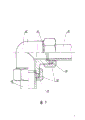
According to a kind of movable pipe joint shown in Figure 4, joint (20) is a valve body, and the inboard at its two ends is provided with shoulder, is processed with sinistral external thread on the outer end.End face at two connected pipes (24) is provided with seal washer (21), is provided with screw thread collar (22) and coupling nut (23) on the end.
Claims (4)
1, a kind of movable pipe joint, comprise joint, seal washer, Female connector fittings, the interior sidecar that it is characterized in that joint (1) has the internal thread of certain-length or is provided with shoulder, and can be processed into square or hexagonal shaped at got on the bus sinistral external thread and the other end outer wall of an end of outer wall, seal washer (2) equals the closed annular body of the rectangular cross-section of the internal diameter of institute's connecting tube and external diameter respectively for internal diameter and external diameter, the interior sidecar of screw thread collar (3) has internal thread and its outer wall one end is processed with two planes that are symmetrical in its axis, the inboard one end car of coupling nut (4) has the sinistral external thread of certain-length and the other end to be provided with shoulder, and its outer wall can be processed into square or hexagonal shaped, the closed annular body that is shaped as the rectangular cross-section of packing ring (9), its internal diameter equals the internal diameter than minor diameter connected tube (13), and its external diameter equals the external diameter than major diameter connected tube (14).
2, a kind of movable pipe joint according to claim 1 is characterized in that joint (1), screw thread collar (3), coupling nut (4) made by cast iron or plain carbon steel.
3, a kind of movable pipe joint according to claim 1 is characterized in that seal washer (2) made by rubber or asbestos or soft metal.
4, a kind of movable pipe joint according to claim 1 is characterized in that packing ring (9) is become by steel or copper.
Priority Applications (1)
| Application Number | Priority Date | Filing Date | Title |
|---|---|---|---|
| CN 90206760 CN2116141U (en) | 1990-05-17 | 1990-05-17 | Pipe joint |
Applications Claiming Priority (1)
| Application Number | Priority Date | Filing Date | Title |
|---|---|---|---|
| CN 90206760 CN2116141U (en) | 1990-05-17 | 1990-05-17 | Pipe joint |
Publications (1)
| Publication Number | Publication Date |
|---|---|
| CN2116141U true CN2116141U (en) | 1992-09-16 |
Family
ID=4887291
Family Applications (1)
| Application Number | Title | Priority Date | Filing Date |
|---|---|---|---|
| CN 90206760 Granted CN2116141U (en) | 1990-05-17 | 1990-05-17 | Pipe joint |
Country Status (1)
| Country | Link |
|---|---|
| CN (1) | CN2116141U (en) |
Cited By (9)
| Publication number | Priority date | Publication date | Assignee | Title |
|---|---|---|---|---|
| WO2010075658A1 (en) * | 2008-12-31 | 2010-07-08 | 浙江华夏阀门有限公司 | A sealing structure with groove and gasket |
| CN103123021A (en) * | 2011-11-21 | 2013-05-29 | 中国航空工业集团公司沈阳发动机设计研究所 | Connection structure of vent line penetrating through engine box |
| CN105135148A (en) * | 2015-10-01 | 2015-12-09 | 罗建华 | Clamping-ring-bearing water pipe quick swing joint |
| CN106062455A (en) * | 2014-02-28 | 2016-10-26 | 株式会社神户制钢所 | Joint unit |
| CN106287037A (en) * | 2016-10-17 | 2017-01-04 | 珠海格力电器股份有限公司 | Purifier and joint design thereof |
| CN107917292A (en) * | 2016-08-29 | 2018-04-17 | 曹如锋 | A kind of pipe connector lug and pipe connector lug application method |
| CN109844389A (en) * | 2016-10-18 | 2019-06-04 | 艾批木有限责任公司 | Plastic tube with mitriform connector |
| CN111486279A (en) * | 2019-01-29 | 2020-08-04 | 中国石油化工股份有限公司 | Adjustable ground lining pipeline union joint |
| CN111486280A (en) * | 2019-01-29 | 2020-08-04 | 中国石油化工股份有限公司 | Freely telescopic ground lining pipeline union joint |
-
1990
- 1990-05-17 CN CN 90206760 patent/CN2116141U/en active Granted
Cited By (13)
| Publication number | Priority date | Publication date | Assignee | Title |
|---|---|---|---|---|
| WO2010075658A1 (en) * | 2008-12-31 | 2010-07-08 | 浙江华夏阀门有限公司 | A sealing structure with groove and gasket |
| CN103123021A (en) * | 2011-11-21 | 2013-05-29 | 中国航空工业集团公司沈阳发动机设计研究所 | Connection structure of vent line penetrating through engine box |
| CN103123021B (en) * | 2011-11-21 | 2015-04-08 | 中国航空工业集团公司沈阳发动机设计研究所 | Connection structure of vent line penetrating through engine box |
| US10550968B2 (en) | 2014-02-28 | 2020-02-04 | Kabushiki Kaisha Kobe Seiko Sho | Joint unit |
| CN106062455A (en) * | 2014-02-28 | 2016-10-26 | 株式会社神户制钢所 | Joint unit |
| CN105135148A (en) * | 2015-10-01 | 2015-12-09 | 罗建华 | Clamping-ring-bearing water pipe quick swing joint |
| CN107917292A (en) * | 2016-08-29 | 2018-04-17 | 曹如锋 | A kind of pipe connector lug and pipe connector lug application method |
| CN106287037B (en) * | 2016-10-17 | 2018-07-10 | 珠海格力电器股份有限公司 | Purifier and joint design thereof |
| CN106287037A (en) * | 2016-10-17 | 2017-01-04 | 珠海格力电器股份有限公司 | Purifier and joint design thereof |
| CN109844389A (en) * | 2016-10-18 | 2019-06-04 | 艾批木有限责任公司 | Plastic tube with mitriform connector |
| US11598468B2 (en) | 2016-10-18 | 2023-03-07 | Ipm S.R.L. | Plastic pipe with bell joint |
| CN111486279A (en) * | 2019-01-29 | 2020-08-04 | 中国石油化工股份有限公司 | Adjustable ground lining pipeline union joint |
| CN111486280A (en) * | 2019-01-29 | 2020-08-04 | 中国石油化工股份有限公司 | Freely telescopic ground lining pipeline union joint |
Similar Documents
| Publication | Publication Date | Title |
|---|---|---|
| CN2116141U (en) | Pipe joint | |
| CN2450492Y (en) | Internal thread locking connector | |
| CN2283173Y (en) | Self-locking pipe connecting piece | |
| CN2098604U (en) | Quick assembling joint of pipeline | |
| CN2039785U (en) | Pipe joint for central heating | |
| CN2443218Y (en) | Extruding pipe joint | |
| CN2203396Y (en) | Pipeline flange connection arrangement for pipe fittings, valves and equipment | |
| CN87210685U (en) | Quick jointer for pipe or tube | |
| CN207921550U (en) | A kind of new hull connector | |
| CN2307169Y (en) | Collar joint | |
| CN2133741Y (en) | Fast movable joint for pipe | |
| CN2191955Y (en) | Quick-acting connector for pipe | |
| CN2208149Y (en) | Quick-fastening sealing pipe joint | |
| CN2209748Y (en) | Pressure-filling type movable joint | |
| CN2166292Y (en) | threaded pipe fitting | |
| CN212643817U (en) | Pipeline connection structure of high leakproofness | |
| CN2386303Y (en) | Double quick assembling coupling | |
| CN2150421Y (en) | Friction resistance joint for pipeline | |
| CN217482276U (en) | Pipe connector for enhancing sealing performance of valve pipe | |
| CN210240863U (en) | Flange connecting piece | |
| CN107906276B (en) | Cutting ferrule type straight-through pipe joint | |
| CN2392968Y (en) | Novel pipe joint | |
| CN2099233U (en) | Quick pipe union | |
| CN2069960U (en) | Convenient joint for steel pipe | |
| CN2295896Y (en) | Pipe joint |
Legal Events
| Date | Code | Title | Description |
|---|---|---|---|
| C06 | Publication | ||
| PB01 | Publication | ||
| C14 | Grant of patent or utility model | ||
| GR01 | Patent grant | ||
| C19 | Lapse of patent right due to non-payment of the annual fee | ||
| CF01 | Termination of patent right due to non-payment of annual fee |