CN211600035U - Semi-linkage support and all-in-one machine - Google Patents
Semi-linkage support and all-in-one machine Download PDFInfo
- Publication number
- CN211600035U CN211600035U CN201922085782.4U CN201922085782U CN211600035U CN 211600035 U CN211600035 U CN 211600035U CN 201922085782 U CN201922085782 U CN 201922085782U CN 211600035 U CN211600035 U CN 211600035U
- Authority
- CN
- China
- Prior art keywords
- semi
- support
- fixed shaft
- upper fixed
- connecting rod
- Prior art date
- Legal status (The legal status is an assumption and is not a legal conclusion. Google has not performed a legal analysis and makes no representation as to the accuracy of the status listed.)
- Active
Links
Images


Landscapes
- Devices For Indicating Variable Information By Combining Individual Elements (AREA)
Abstract
Half linkage support and all-in-one, including the link mechanism of both sides and the last pivot mount of connecting the display screen, its characterized in that: the secondary rotating mechanism is also arranged and comprises an upper fixed shaft and matching holes at two sides of the upper rotating shaft support; one end of the upper fixed shaft is vertically and fixedly connected with an upper connecting rod of the connecting rod mechanism, and the other end of the upper fixed shaft penetrates into the matching hole and is rotatably connected with the matching hole. The utility model discloses a set up secondary slewing mechanism and come free angle regulation and height, need not synchronous adjustment, let the user obtain better use and experience.
Description
Technical Field
The utility model relates to a human-computer interaction display device, specifically speaking are half linkage support and all-in-one.
Background
With the rapid development of science and technology, the mobile payment consumption behavior is generally accepted by the public, and meanwhile, due to the improvement of the safety technology, the face recognition payment is favored by consumers and the development is rapid; some mobile payment devices that assist in new retail sales play an increasingly important role in people's daily life; mobile payment devices play an increasingly important role in the new retail technology revolution; these mobile payment devices, such as office payment kiosk, typically require height and angle adjustments to facilitate use by different users.
At present, most of display devices or all-in-one machine devices can only adjust angles, and some display devices or all-in-one machine devices can adjust heights and angles, but the height and angle adjusting mode cannot have inconvenient places, such as the angle and the height which need to be adjusted synchronously. According to the synchronous linkage support disclosed in the Chinese patent CN201820622813.8, the first fixing piece, the second fixing piece, the first connecting rod and the second connecting rod form a four-bar linkage structure, so that the display screen and the support can move synchronously, and the display screen can rotate by a certain angle while the support moves downwards in a rotating manner, so that the synchronous linkage support is suitable for a relatively exquisite display support structure, and the size of the display support can be reduced. However, in this solution, the first connecting shaft and the connecting piece are fixedly connected, so that the display screen can only move along with the upper end connecting rods of the parallelograms at the two ends of the display screen, and the angle of the display screen cannot be adjusted independently when the user is inconvenient to observe; due to the limitation of the planar linkage mechanism, the height needs to be changed simultaneously when the angle is changed, and the structure that the angle and the height must be synchronously adjusted is inconvenient to use. In addition, the problems of overlarge adjusting torque force, inconvenient adjustment, serious shaking of the touch display screen and the like exist.
Disclosure of Invention
The utility model discloses a current problem aims at providing a semi-linkage support and all-in-one.
In order to achieve the purpose, the utility model adopts the technical proposal that the device comprises a connecting rod mechanism at two sides, an upper rotating shaft bracket connected with a display screen and a secondary rotating mechanism, wherein the secondary rotating mechanism comprises an upper fixed shaft and matching holes at two sides of the upper rotating shaft bracket; one end of the upper fixing shaft is fixedly connected with an upper connecting rod of the connecting rod mechanism in a vertical mode, and the other end of the upper fixing shaft penetrates into the matching hole and is rotatably connected with the rod body and the round hole structure through matching.
Bending plates are arranged on two sides of the upper rotating shaft support, and the bending plates are perpendicular to the support body; and the bending plate is provided with a through matching hole.
The shaft body of the upper fixing shaft penetrating through the matching hole is provided with a limiting blocking piece; the bending plate is provided with an arc-shaped groove, and the limiting blocking piece extends into the arc-shaped groove and slides.
And a torsion spring for adjusting the torque of the upper fixing shaft is arranged on the shaft body of the upper fixing shaft.
The elastic resistance adjusting plate is sleeved on the upper fixing shaft, one.
Wherein, go up the pivot support and pass through keysets and display screen fixed connection.
The connecting rod mechanism is a parallelogram connecting rod mechanism and is formed by connecting an upper connecting rod, a first connecting rod, a second connecting rod and a lower connecting rod which are parallel.
The connecting rod mechanism is characterized by further comprising a support side arm, a cavity is formed in the support side arm, and the connecting rod mechanism is arranged in the cavity.
The utility model also provides an all-in-one with display screen contains foretell semi-linkage support.
Compared with the prior art, the utility model has the advantages that the angle and the height can be freely adjusted by arranging the secondary rotating mechanism without synchronous adjustment, so that the user can obtain better use experience; the bending plate is provided with an arc-shaped groove for the limiting blocking piece to move, so that the display screen can rotate in a specific angle; the adapter plate can be suitable for display screens with different sizes and specifications, so that the applicability of the adapter plate is wider; the torsion spring can adjust the torque, so that the pitching rotating force of the display screen is ensured to be balanced; the lock nut can adjust the resistance on the resistance adjusting sheet, so that the rotation of the rotating shaft is adjusted by the resultant force of the resistance and the torsion spring.
Drawings
Fig. 1 is a schematic structural diagram of an embodiment of the present invention;
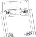
fig. 2 is a schematic view of the structure splitting of the embodiment of the present invention;
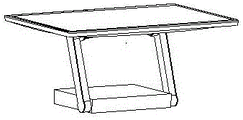
fig. 3 is a schematic view of a usage status of the embodiment of the present invention;
fig. 4 is a schematic view of a usage status of the embodiment of the present invention;
fig. 5 is a schematic view of a usage status of the embodiment of the present invention;
referring to the attached drawings, a connecting rod cover plate 1, an upper fixing shaft 2, an upper connecting rod 3, a support side arm 4, a first connecting rod 5, a second connecting rod 6, a lower fixing shaft 7, a lower connecting rod 8, a lower rotating shaft torsion spring 9, a lower resistance adjusting sheet 10, a lower locking nut 11, an upper limiting baffle 12, a resistance adjusting sheet 13, a locking nut 14, an upper torsion spring 15, a lower limiting baffle 16, a transfer plate 17 and an upper rotating shaft support 18 are arranged on the connecting rod.
Detailed Description
The present invention will now be further described with reference to the accompanying drawings.
Referring to fig. 1 and 2, fig. 1 and 2 show an embodiment of the present invention, the integrated machine includes a base, two sides of the base are rotatably connected with lower ends of parallelogram linkages, respectively, and upper ends of the parallelogram linkages are connected with two sides of an upper rotating shaft support 18, respectively, and a front surface of the upper rotating shaft support 18 is fixedly connected with a display screen (not shown).
Referring to fig. 2, the parallelogram four-bar linkage mechanism is composed of an upper link 3, a first link 5, a second link 6 and a lower link 8, is arranged in the inner cavity of the bracket side arm 4, and is sealed by a link cover plate 1. When a certain force is applied to the bracket side arm 4, the bracket side arm 4 rotates around the lower fixed shaft 7, so that the first connecting rod 5 and the second connecting rod 6 are driven to rotate for a certain angle; the characteristics of the parallelogram link structure enable the first link 5 and the second link 6 to drive the upper link 3 to synchronously rotate by corresponding angles, and simultaneously the upper fixed shaft 2 drives the display screen to correspondingly rotate. The upper connecting rod 3 drives the integrated machine to rotate correspondingly by virtue of the axial friction force provided by the resistance adjusting elastic sheet 13, and the rotating radius of the two upper fixed points is equal to that of the two lower connecting rods 8, so that the upper connecting rod 3 can compensate for the same angle after the lower connecting rods 8 rotate for a certain angle, and the angle between the display screen and the desktop can be kept unchanged.
On the basis of the above, the present embodiment is further provided with a secondary rotating mechanism, which includes the upper fixed shaft 2 and the matching holes on both sides of the upper rotating shaft support 18; one end of the outer side of the upper fixed shaft 2 is vertically and fixedly connected with the rod body of the upper connecting rod 3, and the other end of the upper fixed shaft penetrates through matching holes on the bending plates at two sides of the upper rotary shaft support 2 and is rotatably connected with the upper rotary shaft support.
Further, referring to fig. 2, an upper limit baffle 12 is further arranged on the shaft body of the upper fixing shaft 2 passing through the matching hole; the bending plates on the two sides of the upper rotary shaft support 18 are provided with arc grooves, and the upper limiting blocking pieces 12 extend into the arc grooves and slide in the limited range. Referring to fig. 3-5, since the matching holes of the upper rotating shaft support 18 and the upper fixed shaft 2 are round holes, the upper rotating shaft support 18 can freely rotate within a limit angle, so as not to be limited by the rotation angle of the parallelogram link, i.e. the secondary rotating mechanism can independently operate, and a structure which can flexibly rotate and be used is added.
Similarly, an arc-shaped limiting mechanism groove matched with each other is also formed between the lower limiting baffle 16 and the side arm 4 of the bracket, so that the lower connecting rod 3 is ensured to rotate in a specific angle, and the use safety is ensured.
Further, an upper torsion spring 15 for adjusting the torque of the upper fixing shaft 2 is arranged on the shaft body of the upper fixing shaft, and the torque of the upper torsion spring 15 is different when the display screen rotates to different angles. When the display screen is in a vertical state, the gravity moment is maximum, the torsion moment of the upper torsion spring 15 is also maximum, and the gravity moment and the torsion moment are mutually offset, so that the pitching rotation force of the display screen is relatively balanced, and better user experience is achieved.
In the same way, the torsion moment of the lower fixed shaft 7 is different when the lower torsion spring 9 rotates at different angles on the side wall 4 of the bracket, so that the gravity moment of the integrated machine can be offset, and the labor is saved when the display screen is lifted.
In addition, a locking nut 14 is provided, the locking nut 14 is sleeved on the shaft body of the upper fixed shaft 2 and presses one side of the resistance adjusting elastic sheet 13, and the other side of the resistance adjusting elastic sheet 13 presses the adjusting plate on the upper fixed shaft 2 and generates resistance. Similarly, the lower fixing shaft 7 is provided with a lower locking nut 11 and a lower resistance adjusting sheet 10. In this embodiment, the force of the resistance adjusting piece 10 can be adjusted by tightening or loosening the lock nut 11, so that the force of the rotation of the rotating shaft of the lower link 3 is adjusted by the resultant force of the resistance and the torsion spring.
Preferably, the upper rotating shaft support 18 is fixedly connected with the display screen through the adapter plate 17, and the adapter plate 17 can ensure that the upper rotating shaft support 18 can be used for installing display screens with different sizes and specifications, so that the applicability is wider.
The embodiments of the present invention have been described in conjunction with the accompanying drawings and examples, the structures of which are not intended to limit the present invention, and those skilled in the art can make modifications as required, and all changes and modifications within the scope of the appended claims are within the scope of protection.
Claims (9)
1. The utility model provides a half linkage support, includes the link mechanism of both sides and connects the last pivot mount of display screen, its characterized in that: the secondary rotating mechanism is also arranged and comprises an upper fixed shaft and matching holes at two sides of the upper rotating shaft support; one end of the upper fixed shaft is vertically and fixedly connected with an upper connecting rod of the connecting rod mechanism, and the other end of the upper fixed shaft penetrates into the matching hole and is rotatably connected with the matching hole.
2. The semi-linking bracket of claim 1, wherein: bending plates are arranged on two sides of the upper rotating shaft support, and matching holes penetrating through the bending plates are formed in the bending plates.
3. The semi-linking bracket of claim 2, wherein: a shaft body of the upper fixing shaft penetrating through the matching hole is provided with a limiting blocking piece; the bending plate is provided with an arc-shaped groove, and the limiting blocking piece extends into the arc-shaped groove and slides.
4. The semi-linking bracket of claim 2, wherein: and a torsional spring for adjusting the torque of the upper fixed shaft is arranged on the shaft body of the upper fixed shaft.
5. The semi-linking bracket of claim 4, wherein: the elastic resistance adjusting plate is characterized by also comprising a locking nut which is sleeved on the shaft body of the upper fixed shaft and compresses one side of the resistance adjusting elastic sheet, and the other side of the resistance adjusting elastic sheet compresses an adjusting plate on the upper fixed shaft and generates resistance.
6. The semi-linking bracket of claim 1, wherein: the upper rotating shaft support is fixedly connected with the display screen through the adapter plate.
7. The semi-linking bracket of any of claims 1-6, wherein: the link mechanism is a parallelogram link mechanism and is formed by connecting an upper link rod, a first link rod, a second link rod and a lower link rod which are parallel.
8. The semi-linking bracket of claim 7, wherein: the support is characterized by further comprising a support side arm, a cavity is arranged in the support side arm, and the connecting rod mechanism is arranged in the cavity.
9. The utility model provides an all-in-one with display screen which characterized in that: comprising a semi-interlocking stent according to any one of claims 1 to 8.
Priority Applications (1)
| Application Number | Priority Date | Filing Date | Title |
|---|---|---|---|
| CN201922085782.4U CN211600035U (en) | 2019-11-28 | 2019-11-28 | Semi-linkage support and all-in-one machine |
Applications Claiming Priority (1)
| Application Number | Priority Date | Filing Date | Title |
|---|---|---|---|
| CN201922085782.4U CN211600035U (en) | 2019-11-28 | 2019-11-28 | Semi-linkage support and all-in-one machine |
Publications (1)
| Publication Number | Publication Date |
|---|---|
| CN211600035U true CN211600035U (en) | 2020-09-29 |
Family
ID=72589459
Family Applications (1)
| Application Number | Title | Priority Date | Filing Date |
|---|---|---|---|
| CN201922085782.4U Active CN211600035U (en) | 2019-11-28 | 2019-11-28 | Semi-linkage support and all-in-one machine |
Country Status (1)
| Country | Link |
|---|---|
| CN (1) | CN211600035U (en) |
Cited By (1)
| Publication number | Priority date | Publication date | Assignee | Title |
|---|---|---|---|---|
| CN110822265A (en) * | 2019-12-09 | 2020-02-21 | 深圳市斯蒙奇科技有限公司 | Linkage structure of four-bar linkage rotating shaft |
-
2019
- 2019-11-28 CN CN201922085782.4U patent/CN211600035U/en active Active
Cited By (1)
| Publication number | Priority date | Publication date | Assignee | Title |
|---|---|---|---|---|
| CN110822265A (en) * | 2019-12-09 | 2020-02-21 | 深圳市斯蒙奇科技有限公司 | Linkage structure of four-bar linkage rotating shaft |
Similar Documents
| Publication | Publication Date | Title |
|---|---|---|
| CN108170219B (en) | Integrated computer display screen hovering mechanism and integrated computer comprising same | |
| CN209146675U (en) | Multi-angle display device with incidence regulating mechanism | |
| CN201651697U (en) | Display bracket | |
| CN106594470A (en) | Flexible display screen support arm system | |
| CN210319211U (en) | Support for computer display | |
| CN109521839B (en) | Elevation angle adjustable computer display screen | |
| CN203560691U (en) | A tablet computer support | |
| CN211600035U (en) | Semi-linkage support and all-in-one machine | |
| CN219473242U (en) | Hinge for rotating shaft of display screen | |
| CN215347515U (en) | Computer desk structure capable of relieving elbow fatigue | |
| CN101345093A (en) | Display capable of simultaneously regulating height and visual angle of display screen, and regulation device thereof | |
| WO2004012202A1 (en) | Display rotation shaft | |
| EP4350160A1 (en) | Rotating shaft apparatus and electronic device | |
| CN211176118U (en) | Adjusting device of tablet computer support frame | |
| CN102346988A (en) | Flat panel display device | |
| CN211699348U (en) | Ideological and political education contrast presentation device | |
| CN209977667U (en) | Novel display bracket | |
| CN210398237U (en) | Multi-degree-of-freedom extensible tablet computer support | |
| CN209628987U (en) | A kind of intelligent desk of display screen adjustable-angle | |
| CN201874979U (en) | Rotary pivot device with double rotating shafts | |
| CN207924569U (en) | Integrated computer display screen hovering mechanism and the integrated computer comprising the mechanism | |
| CN216590799U (en) | Balancing device capable of realizing adjustable bearing of support | |
| CN214580064U (en) | Communicator and dispatching equipment | |
| CN219655712U (en) | Stable in structure's adjustable angle's display screen | |
| CN215294352U (en) | Floated dull and stereotyped strutting arrangement |
Legal Events
| Date | Code | Title | Description |
|---|---|---|---|
| GR01 | Patent grant | ||
| GR01 | Patent grant |