CN211584624U - Infusion support convenient to move - Google Patents
Infusion support convenient to move Download PDFInfo
- Publication number
- CN211584624U CN211584624U CN202020093399.3U CN202020093399U CN211584624U CN 211584624 U CN211584624 U CN 211584624U CN 202020093399 U CN202020093399 U CN 202020093399U CN 211584624 U CN211584624 U CN 211584624U
- Authority
- CN
- China
- Prior art keywords
- infusion bag
- infusion
- storage box
- placing groove
- groups
- Prior art date
- Legal status (The legal status is an assumption and is not a legal conclusion. Google has not performed a legal analysis and makes no representation as to the accuracy of the status listed.)
- Expired - Fee Related
Links
Images


Abstract
The utility model discloses an infusion support convenient to remove, include gyro wheel, base, prevent long-pending liquid platform, pillar, infusion bag case, infusion bag flying piece and go up the backup pad, the gyro wheel is located on the base lower wall, prevent that the liquid platform is located on the base, pillar one end is located and is prevented liquid bench, it locates on the pillar other end to go up the backup pad, infusion bag flying piece is rotatable to be located on the backup pad, infusion bag case is located on the pillar. The utility model belongs to the technical field of medical device, specifically indicate a infusion support that can remove and deposit infusion bag and carry out the removal of being convenient for that heats infusion bag.
Description
Technical Field
The utility model belongs to the technical field of medical device, specifically indicate a infusion support convenient to remove.
Background
The infusion support is used for hanging liquid medicine bottle or bag supporting articles for use, the necessary equipment of doctorsing and nurses, it is folding telescopic mainly, ceiling rail formula and vertical, generally when the hospital is beaten the infusion bottle, the nurse all can hang the infusion bottle on the gallows of overhead, nevertheless some patients infusion time has been long, the centre needs to go to the lavatory, current infusion support is generally inconvenient to remove, when infusion patient need leave the infusion position generally must carry the infusion support with that hand that does not infuse or only carry and hang the liquid medicine bottle when only needing to look for suitable position and hang the liquid medicine bottle, this just brings very big inconvenience for infusion patient, for this reason we provide an infusion support convenient to remove.
SUMMERY OF THE UTILITY MODEL
In order to solve the problem, the utility model provides a transfusion stand which can be moved and can be used for storing transfusion bags to heat the transfusion bags and is convenient to move.
In order to realize the above functions, the utility model discloses the technical scheme who takes as follows: a transfusion stand convenient to move comprises rollers, a base, a liquid accumulation preventing platform, a support column, a transfusion bag storage box, a transfusion bag hanging part and an upper support plate, wherein the rollers are arranged on the lower wall of the base; the infusion bag storage box comprises a storage box body, a through hole, an infusion bag placing groove, a placing groove flip and an electric heating plate, wherein the through hole is formed in the center of the storage box body, the storage box body is arranged on the support column through the through hole, the infusion bag placing groove is formed in the storage box body, one end of the placing groove flip is rotatably arranged on the side wall of the infusion bag placing groove, and the electric heating plate is arranged in the infusion bag placing groove.
Further, the storage box body is arranged in a regular polygon shape.
Furthermore, the infusion bag standing grooves are provided with a plurality of groups, and the infusion bag standing grooves of the groups are uniformly arranged on the storage box body in a circumferential manner by taking the through holes as circle centers.
Furthermore, the placing groove flip covers are provided with a plurality of groups, and the number of the group of the placing groove flip covers is the same as that of the group of the infusion bag placing grooves.
Further, the electric heating plate is provided with a plurality of groups, and the number of the electric heating plates of the groups is the same as that of the infusion bag placing grooves of the groups.
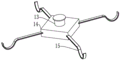
Further, the infusion bag flying piece includes pivot, couple fixed block and infusion bag couple, the pivot is rotatable to be located on the backup pad, the couple fixed block is located in the pivot, the infusion bag couple is located on the couple fixed block.
The utility model adopts the above structure to gain beneficial effect as follows: the utility model provides a pair of infusion support convenient to remove can drive the base through the gyro wheel and remove, prevents that the hydrops from piling up on the base on the hydrops platform, infusion bag can be placed in the infusion bag standing groove to infusion bag through the electrical heating board in to the infusion bag standing groove heats, standing groove flip can turn over to roll over and locate infusion bag standing groove upper end, carries out dustproof processing to infusion bag in the infusion bag standing groove.
Drawings
FIG. 1 is an overall structure diagram of a transfusion stand convenient for moving according to the present invention;
FIG. 2 is a top view of an infusion bag storage box of an infusion stand convenient to move;
fig. 3 is a schematic view of a transfusion bag hanging part of a transfusion stand convenient to move.
The infusion bag hanging piece comprises 1, rollers, 2, a base, 3, a liquid accumulation prevention platform, 4, pillars, 5, an infusion bag storage box, 6, an infusion bag hanging piece, 7, an upper supporting plate, 8, a storage box body, 9, through holes, 10, an infusion bag placing groove, 11, a placing groove turning cover, 12, an electric heating plate, 13, a rotating shaft, 14, a hook fixing block, 15 and infusion bag hooks.
Detailed Description
The technical solution of the present invention will be described in further detail with reference to the following embodiments, and the technical features or the connection relations of the present invention, which are not described in detail, are the prior art adopted.
The present invention will be described in further detail with reference to the accompanying drawings.
As shown in fig. 1-3, the utility model relates to a transfusion stand convenient to move, which comprises a roller 1, a base 2, a liquid accumulation prevention platform 3, a pillar 4, a transfusion bag hanging part 5, a transfusion bag hanging part 6 and an upper supporting plate 7, wherein the roller 1 is arranged on the lower wall of the base 2, the liquid accumulation prevention platform 3 is arranged on the base 2, one end of the pillar 4 is arranged on the liquid accumulation prevention platform 3, the upper supporting plate 7 is arranged on the other end of the pillar 4, the transfusion bag hanging part 6 is rotatably arranged on the upper supporting plate 7, and the transfusion bag storing box 5 is arranged on the pillar 4; the infusion bag storage box 5 comprises a storage box body 8, a through hole 9, an infusion bag placing groove 10, a placing groove flip 11 and an electric heating plate 12, the through hole 9 is arranged in the center of the storage box body 8, the storage box body 8 is arranged on the supporting column 4 through the through hole 9, the infusion bag placing groove 10 is arranged on the storage box body 8, one end of the placing groove flip 11 is rotatably arranged on the side wall of the infusion bag placing groove 10, and the electric heating plate 12 is arranged in the infusion bag placing groove 10.
The storage box body 8 is arranged in a regular polygon shape.
The infusion bag standing grooves 10 are provided with a plurality of groups, and the infusion bag standing grooves 10 of the groups are circumferentially and uniformly arranged on the storage box body 8 by taking the through holes 9 as circle centers.
The placing groove flip covers 11 are provided with a plurality of groups, and the number of the group of the placing groove flip covers 11 is the same as that of the group of the infusion bag placing grooves 10.
The electric heating plate 12 is provided with a plurality of groups, and the number of the electric heating plates 12 is the same as that of the infusion bag placing grooves 10.
During the specific use, when the user needs to remove, accessible gyro wheel 1 can drive base 2 and remove, prevent that long-pending liquid platform 3 can prevent that long-pending liquid from piling up on the base 2, medical personnel can place the infusion bag that needs the infusion in infusion bag standing groove 10, and heat the infusion bag in infusion bag standing groove 10 through electric heating board 12, standing groove flip 11 can turn over to turn over and locate infusion bag standing groove 10 upper end, carry out dustproof processing to the infusion bag in infusion bag standing groove 10, the infusion bag that is infusing can be hung and is fixed on infusion bag couple 15.
The present invention and the embodiments thereof have been described above, but the description is not limited thereto, and the embodiment shown in the drawings is only one of the embodiments of the present invention, and the actual structure is not limited thereto. In summary, those skilled in the art should understand that they should not be limited to the embodiments described above, and that they can design the similar structure and embodiments without departing from the spirit of the invention.
Claims (6)
1. The utility model provides a transfusion frame convenient to remove which characterized in that: the infusion bag hanging part comprises a roller, a base, an anti-liquid accumulation table, a support column, an infusion bag storage box, an infusion bag hanging part and an upper support plate, wherein the roller is arranged on the lower wall of the base; the infusion bag storage box comprises a storage box body, a through hole, an infusion bag placing groove, a placing groove flip and an electric heating plate, wherein the through hole is formed in the center of the storage box body, the storage box body is arranged on the support column through the through hole, the infusion bag placing groove is formed in the storage box body, one end of the placing groove flip is rotatably arranged on the side wall of the infusion bag placing groove, and the electric heating plate is arranged in the infusion bag placing groove.
2. The infusion support convenient to move as claimed in claim 1, wherein: the storage box body is arranged in a regular polygon shape.
3. The infusion support convenient to move as claimed in claim 1, wherein: the infusion bag standing groove is equipped with a plurality of groups, the infusion bag standing groove of a plurality of groups uses the through-hole as the centre of a circle to be the circumference and evenly locates on the case body.
4. The infusion support convenient to move as claimed in claim 1, wherein: the standing groove flip cover is provided with a plurality of groups, and the number of the group of standing groove flip covers is the same as that of the group of infusion bag standing grooves.
5. The infusion support convenient to move as claimed in claim 1, wherein: the electric heating plate is equipped with a plurality of groups, a plurality of groups electric heating plate quantity is the same with a plurality of groups infusion bag standing groove quantity.
6. The infusion support convenient to move as claimed in claim 1, wherein: the infusion bag flying piece comprises a rotating shaft, a hook fixing block and an infusion bag hook, the rotating shaft is rotatably arranged on the upper supporting plate, the hook fixing block is arranged on the rotating shaft, and the infusion bag hook is arranged on the hook fixing block.
Priority Applications (1)
| Application Number | Priority Date | Filing Date | Title |
|---|---|---|---|
| CN202020093399.3U CN211584624U (en) | 2020-01-16 | 2020-01-16 | Infusion support convenient to move |
Applications Claiming Priority (1)
| Application Number | Priority Date | Filing Date | Title |
|---|---|---|---|
| CN202020093399.3U CN211584624U (en) | 2020-01-16 | 2020-01-16 | Infusion support convenient to move |
Publications (1)
| Publication Number | Publication Date |
|---|---|
| CN211584624U true CN211584624U (en) | 2020-09-29 |
Family
ID=72577406
Family Applications (1)
| Application Number | Title | Priority Date | Filing Date |
|---|---|---|---|
| CN202020093399.3U Expired - Fee Related CN211584624U (en) | 2020-01-16 | 2020-01-16 | Infusion support convenient to move |
Country Status (1)
| Country | Link |
|---|---|
| CN (1) | CN211584624U (en) |
-
2020
- 2020-01-16 CN CN202020093399.3U patent/CN211584624U/en not_active Expired - Fee Related
Similar Documents
| Publication | Publication Date | Title |
|---|---|---|
| CN205549119U (en) | Convenient medical treatment infusion shallow | |
| CN211584624U (en) | Infusion support convenient to move | |
| CN203153021U (en) | Medicine rack for western medicine dispensary | |
| CN105749374A (en) | Infusion support | |
| CN209529811U (en) | Infusion device is used in a kind of nursing of new medical | |
| CN210873376U (en) | Portable helping hand infusion support of being convenient for | |
| CN207941005U (en) | A kind of multifunction nursing equipment for internal medicine inspection | |
| CN209864835U (en) | Medical treatment is with multi-functional hanging water frame device | |
| CN207506733U (en) | A kind of Multifunctional medical care vehicle | |
| CN207286400U (en) | A kind of portable transfusion bracket | |
| CN214181329U (en) | Ordinary surgery is with hanging water frame convenient to use | |
| CN214970199U (en) | Multi-layer infusion support | |
| CN213554368U (en) | Movable infusion support | |
| CN215275023U (en) | Infusion support | |
| CN215460828U (en) | Nursing branch of academic or vocational study is with infusion support of being convenient for hang | |
| CN213157315U (en) | Cart for medical care | |
| CN211561349U (en) | Infusion support for tumor chemotherapy patient | |
| CN210250760U (en) | Mobile infusion device based on emergency nursing | |
| CN209236694U (en) | A kind of small-size multifunction medical treatment cart | |
| CN211611053U (en) | Infusion auxiliary stand is used in nursing | |
| CN215309072U (en) | Intelligent automatic infusion support | |
| CN213284890U (en) | Movable support device for multifunctional infusion pump | |
| CN213490059U (en) | Medical nursing tray | |
| CN215780505U (en) | Portable transfusion rod | |
| CN215021212U (en) | Movable infusion vehicle |
Legal Events
| Date | Code | Title | Description |
|---|---|---|---|
| GR01 | Patent grant | ||
| GR01 | Patent grant | ||
| CF01 | Termination of patent right due to non-payment of annual fee |
Granted publication date: 20200929 Termination date: 20220116 |
|
| CF01 | Termination of patent right due to non-payment of annual fee |