CN211552566U - Integrated heat exchanger - Google Patents
Integrated heat exchanger Download PDFInfo
- Publication number
- CN211552566U CN211552566U CN201922162238.5U CN201922162238U CN211552566U CN 211552566 U CN211552566 U CN 211552566U CN 201922162238 U CN201922162238 U CN 201922162238U CN 211552566 U CN211552566 U CN 211552566U
- Authority
- CN
- China
- Prior art keywords
- heat exchange
- heat
- heat exchanger
- layer
- heating
- Prior art date
- Legal status (The legal status is an assumption and is not a legal conclusion. Google has not performed a legal analysis and makes no representation as to the accuracy of the status listed.)
- Active
Links
- 238000005192 partition Methods 0.000 claims abstract description 4
- 239000012530 fluid Substances 0.000 claims description 8
- 239000007769 metal material Substances 0.000 claims description 8
- 238000004804 winding Methods 0.000 claims description 3
- 238000010438 heat treatment Methods 0.000 abstract description 27
- XLYOFNOQVPJJNP-UHFFFAOYSA-N water Substances O XLYOFNOQVPJJNP-UHFFFAOYSA-N 0.000 abstract description 27
- 238000009434 installation Methods 0.000 abstract description 10
- 230000000694 effects Effects 0.000 description 7
- 230000004075 alteration Effects 0.000 description 1
- 230000009286 beneficial effect Effects 0.000 description 1
- 238000010586 diagram Methods 0.000 description 1
- 238000011900 installation process Methods 0.000 description 1
- 238000004519 manufacturing process Methods 0.000 description 1
- 239000000463 material Substances 0.000 description 1
- 238000000034 method Methods 0.000 description 1
- 238000012986 modification Methods 0.000 description 1
- 230000004048 modification Effects 0.000 description 1
- 238000006467 substitution reaction Methods 0.000 description 1
- 239000002699 waste material Substances 0.000 description 1
Images


Abstract
The utility model discloses an integral type heat exchanger, include: the heat exchange layer comprises a plurality of heat exchange tubes and adjacent heat exchange tubes; the connecting pipe is used for connecting the end parts of the adjacent heat exchange pipes; the partition plate is arranged on the heat exchange layer and sequentially divides the heat exchange layer into a plurality of heat exchange areas and connecting areas; the connecting area and the heat exchange area form an integrated structure, and the connecting mode that connecting pipes are needed between the existing heating modules is replaced, so that the product structure and the installation procedure are greatly simplified, the installation efficiency is improved, and meanwhile, the leakage problem caused by installation errors can be avoided when the heating modules are connected; water all can carry out the heat transfer through each heating module when whenever through same heat exchange tube, and the combustor of each heating module can also realize the efficient heat exchange under the condition that keeps same heating power, improves heat utilization rate, and it is extravagant to reduce heat energy.
Description
Technical Field
The utility model relates to a water heating equipment technique, in particular to integral type heat exchanger.
Background
The existing water heating equipment such as a hot water boiler or a steam boiler usually adopts a modular structure, heat exchangers of all heating modules are connected through connecting pipes, interfaces need to be well sealed to prevent hot water or steam from leaking, and the connecting pipes are time-consuming and labor-consuming to install in the production process; in the water heating process, the heat exchangers of all the heating modules exchange heat and then circulate to the heat exchanger of the next heating module, so that when water is heated gradually and then circulates to the heating module behind, the heat energy utilization rate is low, and heat energy is wasted.
SUMMERY OF THE UTILITY MODEL
The present invention aims to solve at least one of the above-mentioned technical problems in the related art to a certain extent. Therefore, the utility model provides an integral type heat exchanger can improve installation effectiveness and heat transfer effect.
In order to achieve the above purpose, the technical scheme of the utility model is as follows:
according to the utility model discloses an integral type heat exchanger of first aspect embodiment, include: the heat exchange layer comprises a plurality of heat exchange tubes and adjacent heat exchange tubes; the connecting pipe is used for connecting the end parts of the adjacent heat exchange pipes; and the partition plates are arranged on the heat exchange layer and sequentially divide the heat exchange layer into a plurality of heat exchange areas and connecting areas.
According to the utility model discloses integral type heat exchanger has following beneficial effect at least: the connecting area and the heat exchange area form an integrated structure, and the connecting mode that connecting pipes are needed between the existing heating modules is replaced, so that the product structure and the installation procedure are greatly simplified, the installation efficiency is improved, and meanwhile, the leakage problem caused by installation errors can be avoided when the heating modules are connected; water all can carry out the heat transfer through each heating module when whenever through same heat exchange tube, and the combustor of each heating module can also realize the efficient heat exchange under the condition that keeps same heating power, improves heat utilization rate, and it is extravagant to reduce heat energy.
According to some embodiments of the present invention, the heat exchange tube outer wall corresponding to the position where the heat exchange area is located is provided with a fin.
According to some embodiments of the utility model, including at least two-layer the heat transfer layer passes through between each heat transfer layer the connecting pipe is connected.
According to some embodiments of the present invention, a fluid disturbing body is installed in the heat exchange tube.
According to some embodiments of the invention, the fluid is wound from a strip of metal material into a helix.
According to some embodiments of the invention, the turbulent fluid is wound in a spiral from a sheet of metallic material.
Additional aspects and advantages of the invention will be set forth in part in the description which follows and, in part, will be obvious from the description, or may be learned by practice of the invention.
Drawings
The above and/or additional aspects and advantages of the present invention will become apparent and readily appreciated from the following description of the embodiments, taken in conjunction with the accompanying drawings of which:
fig. 1 is a schematic structural diagram of the present invention;
fig. 2 is a front view of the present invention;
fig. 3 is an enlarged view of the partial view a of fig. 1 of the present invention;
FIG. 4 is a view of one embodiment of the spoiler of the present invention;
fig. 5 is a view of one embodiment of the spoiler of the present invention.
Detailed Description
Reference will now be made in detail to embodiments of the present invention, examples of which are illustrated in the accompanying drawings, wherein like reference numerals refer to the same or similar elements or elements having the same or similar function throughout. The embodiments described below with reference to the drawings are exemplary and intended to be used for explaining the present invention, and should not be construed as limiting the present invention.
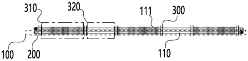
Referring to fig. 1, 2 and 3, an integrated heat exchanger includes: the heat exchange layer 100 comprises a plurality of heat exchange tubes 110, and the adjacent heat exchange tubes 110; a connection pipe 200 for connecting ends of the adjacent heat exchange pipes 110; and a partition 300 installed on the heat exchange layer 100 to divide the heat exchange layer 100 into a plurality of heat exchange regions 310 and a connection region 320 in sequence.
As shown in fig. 1, 2 and 3, the heat exchange layer 100 is formed by installing a plurality of heat exchange tubes 110 side by side, the ports of adjacent heat exchange tubes 110 are connected by a U-shaped connecting tube 200, one port of the heat exchange tube 110 positioned at the frontmost position serves as a water inlet 120 of the heat exchange layer 100, and one port of the heat exchange tube 110 positioned at the rearmost position serves as a water outlet 130; during installation, the heat exchange area 310 of the heat exchange layer 100 is installed in a heating module of the water heating equipment, a burner in the heating module heats the heat exchange area 310, the connection area 320 is positioned between two adjacent heating modules, namely, the connection area 320 and the heat exchange area 310 form an integrated heat exchange tube 110 structure, the connection mode of connecting tubes required by the existing heat exchanger between the heating modules is replaced, the product structure and the installation process are greatly simplified, the installation efficiency is improved, and meanwhile, the problem of leakage caused by installation errors in connection between the heating modules is avoided; in addition, when the heating device is used, water enters the heat exchange tubes 110 from the water inlet 120, then flows along the heat exchange tubes 110 in sequence, and is discharged from the water outlet 130, namely, the water can exchange heat through the heating modules when passing through the same heat exchange tube 110, and the burners of the heating modules can realize efficient heat exchange under the condition of keeping the same heating power, so that the heat utilization rate is improved, and the heat waste is reduced.
In some embodiments of the present invention, the fins 111 are installed on the outer wall of the heat exchange tube 110 corresponding to the position of the heat exchange region 310, and the fins 111 are used to increase the heat exchange area of the heat exchange region 310, thereby increasing the heat exchange effect.
In some embodiments of the present invention, the integrated heat exchanger includes at least two heat exchange layers 100, and each heat exchange layer 100 is connected to another heat exchange layer through the connection pipe 200; water enters from the water inlet 120 of the heat exchange layer 100 on one layer, and after the heat exchange tubes 110 on the layer flow for heat exchange, the water enters from the water outlet 130 of the layer to the water inlet 120 of the heat exchange layer 100 on the other layer for heat exchange again, so that the heat exchange path of the water is increased, and the heat exchange effect and the heat energy utilization rate are improved.
Referring to fig. 4, in the further embodiment of the present invention, the spiral spoiler 400 is installed in the heat exchange tube 110, and when water flows in the heat exchange tube 110, the spoiler 400 has a spoiler effect on water, so that the water fully contacts with the inner wall of the heat exchange tube 110, and the heat exchange effect is further improved.
Referring to fig. 4, in some embodiments of the present invention, the turbulent flow body 400 is formed by winding a strip-shaped metal material into a spiral shape, and the turbulent flow body has a shape similar to a spiral spring after being formed, so that the material cost of the turbulent flow body 400 can be reduced by using the strip-shaped metal material under the effect of realizing turbulent flow to water.
Referring to fig. 5, in some embodiments of the present invention, the fluid disturbing body 400 is made of a sheet metal material and wound into a spiral shape, the fluid disturbing body 400 is made of a sheet metal material, water flows between the wall surface of the fluid disturbing body 400 and the inner wall of the heat exchanging pipe 110, and the contact between water and the inner wall of the heat exchanging pipe 110 is increased at the same flow rate, so as to further improve the heat exchanging effect.
Although embodiments of the present invention have been shown and described, it is understood that the above embodiments are exemplary and should not be construed as limiting the present invention, and that variations, modifications, substitutions and alterations can be made to the above embodiments by those of ordinary skill in the art without departing from the scope of the present invention.
Claims (6)
1. An integrated heat exchanger, comprising:
the heat exchange layer (100) comprises a plurality of heat exchange tubes (110), and the adjacent heat exchange tubes (110);
a connection pipe (200) for connecting ends of the adjacent heat exchange pipes (110);
and a partition plate (300) installed on the heat exchange layer (100) to divide the heat exchange layer (100) into a plurality of heat exchange areas (310) and a connection area (320) in sequence.
2. The integrated heat exchanger of claim 1, wherein: and fins (111) are arranged on the outer wall of the heat exchange tube (110) corresponding to the position of the heat exchange zone (310).
3. The integrated heat exchanger of claim 1, wherein: the heat exchange layer comprises at least two layers of heat exchange layers (100), and the heat exchange layers (100) are connected through the connecting pipe (200).
4. The integrated heat exchanger of claim 1, wherein: a spiral flow disturbing body (400) is arranged in the heat exchange tube (110).
5. The integrated heat exchanger of claim 4, wherein: the fluid disturbing body (400) is formed by winding a strip-shaped metal material into a spiral shape.
6. The integrated heat exchanger of claim 4, wherein: the fluid disturbing body (400) is formed by winding a sheet-shaped metal material into a spiral shape.
Priority Applications (1)
| Application Number | Priority Date | Filing Date | Title |
|---|---|---|---|
| CN201922162238.5U CN211552566U (en) | 2019-12-05 | 2019-12-05 | Integrated heat exchanger |
Applications Claiming Priority (1)
| Application Number | Priority Date | Filing Date | Title |
|---|---|---|---|
| CN201922162238.5U CN211552566U (en) | 2019-12-05 | 2019-12-05 | Integrated heat exchanger |
Publications (1)
| Publication Number | Publication Date |
|---|---|
| CN211552566U true CN211552566U (en) | 2020-09-22 |
Family
ID=72504890
Family Applications (1)
| Application Number | Title | Priority Date | Filing Date |
|---|---|---|---|
| CN201922162238.5U Active CN211552566U (en) | 2019-12-05 | 2019-12-05 | Integrated heat exchanger |
Country Status (1)
| Country | Link |
|---|---|
| CN (1) | CN211552566U (en) |
Cited By (1)
| Publication number | Priority date | Publication date | Assignee | Title |
|---|---|---|---|---|
| CN116222264A (en) * | 2023-03-23 | 2023-06-06 | 无锡市冠云换热器有限公司 | High-efficient heat preservation leak protection heat exchanger |
-
2019
- 2019-12-05 CN CN201922162238.5U patent/CN211552566U/en active Active
Cited By (2)
| Publication number | Priority date | Publication date | Assignee | Title |
|---|---|---|---|---|
| CN116222264A (en) * | 2023-03-23 | 2023-06-06 | 无锡市冠云换热器有限公司 | High-efficient heat preservation leak protection heat exchanger |
| CN116222264B (en) * | 2023-03-23 | 2024-02-13 | 无锡市冠云换热器有限公司 | High-efficient heat preservation leak protection heat exchanger |
Similar Documents
| Publication | Publication Date | Title |
|---|---|---|
| KR100645734B1 (en) | Heat exchanger of condensing boiler for heating and hot-water supply | |
| EA019912B1 (en) | Heat exchanger | |
| CN102901222A (en) | Forced finned straight pipe dual-ring-shaped condensation heat-supply heat exchanger | |
| CN201628245U (en) | Steam air heater | |
| CN211552566U (en) | Integrated heat exchanger | |
| CN204007242U (en) | A kind of plate type heat exchanger | |
| CN105546823B (en) | Frame-type plate heat-exchange device and water heater, wall-hung boiler, commercial boiler | |
| CN211552577U (en) | Turbulent flow structure for heat exchanger | |
| CN207391389U (en) | A kind of liquor production is with being quickly cooled down tank | |
| CN101799248A (en) | High-efficiency Taichi modular high-efficiency heat exchanger | |
| CN201666746U (en) | High-efficiency Tai Chi module high-speed heat exchange device | |
| CN213021095U (en) | Flue gas condensation energy-saving device | |
| KR100820554B1 (en) | Heat storage tank with heat exchanger with expansion tank function | |
| CN104006683A (en) | Plate heat exchanger | |
| CN216114802U (en) | Multi-stage shell and tube condenser | |
| CN212205072U (en) | Efficient combustion heat exchange device and efficient water heating equipment | |
| CN210241714U (en) | Low end difference type heating network heater | |
| CN216049247U (en) | Low-pressure heater | |
| CN209840791U (en) | Energy-saving external recooling heat supply network heater | |
| CN216815117U (en) | Heat exchanger and gas heating water heater | |
| CN114809989B (en) | Device for heating wellhead natural gas on line and application | |
| CN213873924U (en) | Waste heat recovery device for boiler | |
| CN217383954U (en) | High-reliability collecting pipe | |
| CN211372370U (en) | Annular heat exchange tube panel | |
| CN203642498U (en) | Highly efficient heat exchanger |
Legal Events
| Date | Code | Title | Description |
|---|---|---|---|
| GR01 | Patent grant | ||
| GR01 | Patent grant |