CN211550905U - Well pump line mending-leakage device - Google Patents
Well pump line mending-leakage device Download PDFInfo
- Publication number
- CN211550905U CN211550905U CN201922484367.6U CN201922484367U CN211550905U CN 211550905 U CN211550905 U CN 211550905U CN 201922484367 U CN201922484367 U CN 201922484367U CN 211550905 U CN211550905 U CN 211550905U
- Authority
- CN
- China
- Prior art keywords
- flange
- well pump
- plate
- pump line
- fixed
- Prior art date
- Legal status (The legal status is an assumption and is not a legal conclusion. Google has not performed a legal analysis and makes no representation as to the accuracy of the status listed.)
- Active
Links
Images


Landscapes
- Structures Of Non-Positive Displacement Pumps (AREA)
Abstract
The utility model relates to a well pump line trapping devices, its technical scheme main points are: including two semicircle pipes, each rigid coupling in the both sides of every semicircle pipe extrados face has a first fixed plate, and two first fixed plates are located the coplanar, offer the fixed orifices that a plurality of is used for the bolt to wear to establish on every first fixed plate, and the one end rigid coupling of semicircle pipe has one to paste the clamp plate that leans on in flange one side, is provided with on the clamp plate to be used for holding the chamber that holds of bolt on the flange, fixes through a plurality of bolt and nut between two relative first fixed plates. The utility model has the advantages that: and (4) repairing the leak at the joint of the well pump pipe and the flange in time.
Description
Technical Field
The utility model relates to a for water route pipeline maintenance equipment field, concretely relates to well pump line trapping devices.
Background
In large scale ground water intake projects, it is often necessary to build a water intake system-well group consisting of many wells. Well cluster systems can be divided into gravity flow well clusters, siphon well clusters, horizontal or deep well (vertical) or submersible pump water-intake well clusters and air-lift water-intake well clusters, depending on the method of taking water from the wells and the manner of collecting well water.
In the process of pumping underground water, a plurality of well pump pipes are required to be connected end to end, flanges are arranged at two ends of each well pump pipe, and two adjacent well pump pipes are connected and fixed with each other through the flanges.
However, after the well pump pipe is used for a long time, the sealing ring clamped between the flanges is aged, so that water leakage is easily caused at the flanges, and further, corrosion is easily caused at the connecting part of the well pump pipe and the flanges.
SUMMERY OF THE UTILITY MODEL
Not enough to prior art exists, one of the purposes of the utility model is to provide a well pump line mending-leakage device, its advantage is in time repaired the leak of well pump line and flange joint department.
The above technical purpose of the present invention can be achieved by the following technical solutions:
the utility model provides a well pump line trapping devices, includes two semicircle pipes, and each rigid coupling in the both sides of every semicircle outside the tubes cambered surface has a first fixed plate, and two first fixed plates are located the coplanar, have seted up the fixed orifices that a plurality of is used for the bolt to wear to establish on every first fixed plate, and the one end rigid coupling of semicircle pipe has one to paste the clamp plate that leans on in flange one side, is provided with the chamber that holds that is used for holding the bolt on the flange on the clamp plate, fixes through a plurality of bolt nuts between two relative first fixed plates.
Through adopting above-mentioned technical scheme, the staff is when fixing the mending-leakage device, at first encircle two semicircle pipes on the outer peripheral face of well pump line, make the leak source of well pump line be located the intrados of one of them semicircle pipe, then closely press the clamp plate and establish on the flange, the fixed plate that rethread bolt nut will correspond pastes closely, thereby closely paste two semicircle pipes and the outer peripheral face of well pump line, make the difficult diffusion everywhere of liquid of leak source, even there is the trend of flange direction diffusion the liquid of leak source, because the pressure of clamp plate is established, increased the area of contact with the flange, thereby the diffusion of liquid has been suppressed, good mending-leakage effect has been played.
The present invention may be further configured in a preferred embodiment as: and a gap is reserved between the first fixing plate and the edge of the semicircular pipe.
Through adopting above-mentioned technical scheme, because first fixed plate leaves the interval with semicircle pipe border for leave the space between two relative first fixed plates, make bolt and nut at the in-process of twisting soon, provide the deformation space for first fixed plate, make two semicircle pipes inseparabler with the laminating of well pump line, make the water pressure of leak source be difficult for breaching the stifled of semicircle pipe.
The present invention may be further configured in a preferred embodiment as: the two pressing plates are arranged in a surrounding mode to form a circular ring, a hoop used for fastening the two pressing plates is arranged on the outer circumferential surface of each pressing plate in a surrounding mode, two second fixing plates are fixedly connected to two ends of the hoop in a perpendicular mode respectively, and the two second fixing plates are fixed to each other through bolts and nuts.
Through adopting above-mentioned technical scheme, because the clamp plate receives the semicircle pipe fixed, closely laminate the back when the semicircle pipe, can not ensure the compactness of laminating between two clamp plates, encircle two clamp plates with the hoop this moment, then through two tip with the hoop of screw bolt and nut be close to each other for two clamp plates paste tightly each other, have reduced the gap of laminating department, have reduced the condition of leaking.
The present invention may be further configured in a preferred embodiment as: a plurality of fastening components used for fixing the pressure plate and the flange mutually are arranged on one side of the pressure plate, which is far away from the flange;
the fastening assembly comprises a U-shaped limiting part, one end of the U-shaped limiting part is hinged to the pressing plate, the other end of the U-shaped limiting part is in threaded position on one side, away from the pressing plate, of the flange, and the end portion of the U-shaped limiting part is in threaded connection with a fastening bolt which abuts against the flange.
Through adopting above-mentioned technical scheme, after clamp plate and flange laminated each other, in order to improve the effort between clamp plate and the flange, the staff will rotate through the articulated of U type locating part, make the other end of U type locating part rotate the opposite side of flange, and rethread fastening bolt tip drives U type locating part and applys pressure to the clamp plate surface to it is closely close to by the flange to drive the clamp plate, reduces and pastes to the gap to pasting between clamp plate and the flange.
The present invention may be further configured in a preferred embodiment as: and an annular first sealing gasket is embedded on the inner arc surface of the semicircular pipe.
Through adopting above-mentioned technical scheme, closely laminating when the semicircle pipe when the periphery of well pump line, revolve through bolt and nut's fixed revolving to it is inseparabler that messenger's semicircle pipe and well pump line are outer to paste, thereby makes first sealed pad press deformation, has filled the semicircle pipe and has pasted the gap that pastes the border, has improved the seal of semicircle pipe shutoff.
The present invention may be further configured in a preferred embodiment as: and one side of the pressure plate, which faces the flange, is embedded with an annular second sealing gasket along the contour of the pressure plate.
Through adopting above-mentioned technical scheme, when the clamp plate closely pressed on the flange, drive the sealed pad of second and produce deformation to filled the gap of leaning on next between clamp plate and the flange, improved the seal between clamp plate and the flange.
The present invention may be further configured in a preferred embodiment as: the interior cambered surface of semicircle pipe is gone up to inlay along the axial of semicircle pipe and is equipped with a plurality of and separate the sealing strip, separates the both ends of sealing strip and links up each other with first sealed pad.
Through adopting above-mentioned technical scheme, separate the cooperation setting of sealing strip and first sealed pad, separate the intraductal cambered surface of semicircle and form a plurality of and prevent stifled room for when semicircle pipe and well pump pipe closely paste and lean on, restricted the flow of rivers, even rivers have broken through separating the stifled of preventing of sealing strip, also can be blocked by all the other sealing strips of separating, thereby has mentioned good effect that blocks water.
To sum up, the utility model discloses following beneficial effect has:
firstly, leak repairing is carried out on leak points of the well pump pipe in time. The two semicircular pipes are mutually fixed in an encircling way and are tightly abutted by the pressing plate and the flange, so that the water blocking effect is greatly improved;
and secondly, the water-blocking effect is improved. The cooperation setting of separating sealing strip and first sealed pad separates the intraductal cambered surface of semicircle and forms a plurality of and prevent stifled room for when semicircle pipe and well pump pipe closely paste and lean on, restricted the flow of rivers, even rivers have broken through separating the stifled of preventing of sealing strip, also can be blocked by all the other sealing strips of separating, thereby has mentioned the good effect of blocking water.
Drawings
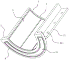
FIG. 1 is a schematic view of the overall construction of a leakage repairing device;
FIG. 2 is a schematic view showing the inner wall structure of the semicircular pipe;
fig. 3 is a schematic structural view embodying the fastening assembly.
In the figure, 1, a well pump pipe; 11. a flange; 2. a semicircular tube; 21. a first fixing plate; 211. a fixing hole; 3. pressing a plate; 31. an accommodating chamber; 4. a hoop; 41. a second fixing plate; 5. a fastening assembly; 51. a U-shaped limiting part; 52. fastening a bolt; 6. a first gasket; 7. separating the sealing strips; 8. a second gasket.
Detailed Description
The present invention will be described in further detail with reference to the accompanying drawings.
The utility model provides a well pump line trapping devices, as shown in figure 1, including two semicircle pipes 2, each rigid coupling has two first fixed plates 21 on 2 extrados surfaces of every semicircle pipe, and first fixed plate 21 lays along the axial direction of semicircle pipe 2, and two first fixed plates 21 are located the both sides of semicircle pipe 2 to two first fixed plates 21 are located the coplanar towards one side of well pump line 1, and evenly seted up three fixed orifices 211 along the length direction of first fixed plate 21 on every first fixed plate 21 moreover. When two semicircle pipes 2 enclose and establish at well pump line 1 global, the staff can wear to establish the bolt in two relative first fixed plate 21's fixed orifices 211, then through mutually supporting of nut and bolt to it is fixed with two semicircle pipe 2 laminatings.
As shown in fig. 1, the first fixing plate 21 and the semicircular pipe 2 correspond to each other and are left at an interval, when two semicircular pipes 2 are clamped and arranged on the outer peripheral surface of the well pump pipe 1, the two first fixing plates 21 are arranged at intervals, and when the bolt and the nut are screwed mutually, the first fixing plates 21 are arranged at intervals, so that the deformation space of the first fixing plates 21 is reserved, the two semicircular pipes 2 are abutted to the end faces, and the gap is reduced.
As shown in fig. 1 and 2, a semicircular pressing plate 3 is fixedly connected to one end of each semicircular pipe 2 facing the flange 11, and a containing cavity 31 for containing bolts and nuts on the flange 11 is formed in one side of the pressing plate 3 facing the flange 11, so that when the pressing plate 3 is attached to the surface of the flange 11, the bolts are contained in the containing cavity 31, and gaps between the pressing plate 3 and the flange 11 are reduced. When liquid leaks from the joint of the well pump pipe 1 and the flange 11, the contact area between the pressure plate 3 and the flange 11 is increased, so that leaked moisture is not easy to diffuse on the flange 11, and the water blocking effect is improved.
As shown in fig. 3, in order to improve the connection tightness between the two pressing plates 3, a hoop 4 is arranged around the outer circumferential surfaces of the two pressing plates 3, the width of the hoop 4 is equal to the thickness of the pressing plates 3, a second fixing plate 41 is fixedly connected to each of the two ends of the hoop 4, a bolt is arranged on the two second fixing plates 41 in a penetrating manner, and the hoop 4 is tightly encircled on the outer circumferential surfaces of the two pressing plates 3 through the cooperation of the nut and the bolt, so that the contact end surfaces of the two pressing plates 3 are closer to each other, and a water blocking effect is achieved.
As shown in fig. 3, each pressure plate 3 is provided with 3 fastening assemblies 5 on the side facing away from the flange 11 for abutting against the flange 11. The fastening assembly 5 comprises a U-shaped limiting member 51, and one end of the U-shaped limiting member 51 is hinged to a side of the pressure plate 3 away from the flange 11. After the two semicircular pipes 2 are fixed to each other, the pressing plate 3 abuts against the surface of the flange 11, then the other end of the U-shaped limiting part 51 rotates towards the other side of the flange 11, and the other end of the U-shaped limiting part 51 is located below the flange 11, the other end of the U-shaped limiting part 51 is in threaded connection with a fastening bolt 52, the fastening bolt 52 is parallel to the axis of the well pump pipe 1, and the head of the fastening bolt 52 abuts against the lower surface of the flange 11 by screwing the fastening bolt 52 and the thread of the U-shaped limiting part 51, so that the side wall of the U-shaped limiting part 51 is driven to abut against the upper surface of the pressing plate 3, and the abutting tightness between the pressing plate 3 and the flange 11 is increased. Because all be provided with three fastening components 5 on every clamp plate 3 for each region of clamp plate 3 can both be stable receive the extrusion force of U type locating part 51, has reduced the space between clamp plate 3 and the flange 11, has played good effect of blocking water.
As shown in fig. 2, the intrados of every semicircle pipe 2 inlays and is equipped with annular first sealed pad 6, and first sealed pad 6 is located 2 border departments of semicircle pipe, along with the reciprocal anchorage of relative first fixed plate 21 for semicircle pipe 2 is inseparable leans on the outer peripheral face at well pump line 1 in turn, thereby drives first sealed pad 6 elastic deformation, makes first sealed pad 6 fill the gap of leaning on in turn between well pump line 1 and 2 inner walls of semicircle pipe, has played good effect of blocking water. And the inner wall of the semicircular pipe 2 is embedded with three separation sealing strips 7 along the axial direction of the well pump pipe 1, and the two ends of each separation sealing strip 7 are mutually connected with the corresponding first sealing gasket 6. When semicircle pipe 2 and well pump line 1 paste each other and lean on, through 6 boxes of first sealed pad of separating mutually supporting of sealing strip 7 for 2 inner walls of semicircle pipe form a plurality of airtight independent cavities that block water, thereby improved the effect that blocks water of mending leakage device.
As shown in fig. 2, an annular second gasket 8 is embedded in the side of the pressure plate 3 facing the flange 11, and the second gasket 8 is located at the edge of the pressure plate 3. When the pressing plate 3 is closely abutted to the flange 11, the second sealing gasket 8 fills up a contact gap between the pressing plate 3 and the flange 11 through elastic deformation, a good water blocking effect is achieved, and diffusion of leaked liquid is limited.
The implementation principle of the embodiment is as follows: the staff places two semicircle pipes 2 at the leak source department of well pump line 1 at first, then with clamp plate 3 inseparable leaning on flange 11 next to, through screwing each other of bolt and nut for two first fixed plates 21 that correspond lean on closely, then rotate U type locating part 51 to the opposite side of flange 11, twist through fastening bolt 52 soon, make clamp plate 3 and flange 11 next to lean on closely to realize the shutoff to the leak source.
The embodiment of this specific implementation mode is the preferred embodiment of the present invention, not limit according to this the utility model discloses a protection scope, so: all equivalent changes made according to the structure, shape and principle of the utility model are covered within the protection scope of the utility model.
Claims (7)
1. The utility model provides a well pump line trapping devices which characterized in that: including two semicircle pipes (2), each rigid coupling in both sides of every semicircle pipe (2) extrados face has a first fixed plate (21), two first fixed plates (21) are located the coplanar, set up fixed orifices (211) that a plurality of is used for the bolt to wear to establish on every first fixed plate (21), the one end rigid coupling of semicircle pipe (2) has one to paste clamp plate (3) of leaning on in flange (11) one side, be provided with on clamp plate (3) and be used for holding chamber (31) that hold of bolt on flange (11), it is fixed through a plurality of bolt and nut between two relative first fixed plates (21).
2. A well pump line lost circulation device of claim 1, wherein: and a gap is reserved between the first fixing plate (21) and the edge of the semicircular pipe (2).
3. A well pump line lost circulation device of claim 1, wherein: the two pressing plates (3) are arranged in a surrounding mode to form a circular ring, a hoop (4) used for fastening the two pressing plates (3) is arranged on the outer circumferential surface of each pressing plate (3), two second fixing plates (41) are fixedly connected to two ends of the hoop (4) in a perpendicular mode respectively, and the two second fixing plates (41) are fixed to each other through bolts and nuts.
4. A well pump line lost circulation device of claim 1, wherein: a plurality of fastening components (5) used for fixing the pressure plate (3) and the flange (11) to each other are arranged on one side of the pressure plate (3) departing from the flange (11);
the fastening assembly (5) comprises a U-shaped limiting part (51), one end of the U-shaped limiting part (51) is hinged to the pressing plate (3), the other end of the U-shaped limiting part (51) is in threaded connection with one side, deviating from the pressing plate (3), of the flange (11), and the end of the U-shaped limiting part (51) is in threaded connection with a fastening bolt (52) which is in contact with the flange (11).
5. A well pump line lost circulation device of claim 1, wherein: an annular first sealing gasket (6) is embedded on the inner arc surface of the semicircular pipe (2).
6. A well pump line lost circulation device of claim 1, wherein: one side of the pressing plate (3) facing the flange (11) is embedded with an annular second sealing gasket (8) along the contour of the pressing plate (3), and the second sealing gasket (8) is mutually connected with the first sealing gasket (6).
7. A well pump line lost circulation device of claim 5, wherein: the axial along semicircle pipe (2) is inlayed on semicircle pipe (2) intrados and is equipped with a plurality of separation sealing strip (7), separates the both ends of sealing strip (7) and links up each other with first sealed pad (6).
Priority Applications (1)
| Application Number | Priority Date | Filing Date | Title |
|---|---|---|---|
| CN201922484367.6U CN211550905U (en) | 2019-12-30 | 2019-12-30 | Well pump line mending-leakage device |
Applications Claiming Priority (1)
| Application Number | Priority Date | Filing Date | Title |
|---|---|---|---|
| CN201922484367.6U CN211550905U (en) | 2019-12-30 | 2019-12-30 | Well pump line mending-leakage device |
Publications (1)
| Publication Number | Publication Date |
|---|---|
| CN211550905U true CN211550905U (en) | 2020-09-22 |
Family
ID=72512851
Family Applications (1)
| Application Number | Title | Priority Date | Filing Date |
|---|---|---|---|
| CN201922484367.6U Active CN211550905U (en) | 2019-12-30 | 2019-12-30 | Well pump line mending-leakage device |
Country Status (1)
| Country | Link |
|---|---|
| CN (1) | CN211550905U (en) |
Cited By (1)
| Publication number | Priority date | Publication date | Assignee | Title |
|---|---|---|---|---|
| CN114962822A (en) * | 2022-06-16 | 2022-08-30 | 中国核工业第五建设有限公司 | Flange gasket mounting and positioning device and method |
-
2019
- 2019-12-30 CN CN201922484367.6U patent/CN211550905U/en active Active
Cited By (2)
| Publication number | Priority date | Publication date | Assignee | Title |
|---|---|---|---|---|
| CN114962822A (en) * | 2022-06-16 | 2022-08-30 | 中国核工业第五建设有限公司 | Flange gasket mounting and positioning device and method |
| CN114962822B (en) * | 2022-06-16 | 2023-10-27 | 中国核工业第五建设有限公司 | Flange gasket mounting and positioning device and method |
Similar Documents
| Publication | Publication Date | Title |
|---|---|---|
| CN204677971U (en) | Fiber reinforced plastic pipe seal connection | |
| CN211550905U (en) | Well pump line mending-leakage device | |
| CN210920557U (en) | Valve inlet pipeline junction leaks shutoff sealing fixture | |
| CN106122639A (en) | A kind of hose connection device | |
| CN205402086U (en) | Pipeline that leaks is salvageed and is used sealing member | |
| CN214116913U (en) | Assembled inspection shaft | |
| CN206988623U (en) | A kind of deep basal pit ditch underground pipelines connect head | |
| CN212338585U (en) | Emergency connection device for pipeline fracture | |
| CN214116914U (en) | Assembly structure of inspection well | |
| CN218378121U (en) | Connecting device for water supply and drainage | |
| CN218719488U (en) | Water pipe mounting structure | |
| CN216666904U (en) | Steel epoxy sleeve | |
| CN214534922U (en) | Building water supply and drainage pipeline | |
| CN219673609U (en) | Flange with linkage locking function | |
| CN207213490U (en) | A kind of low pressure pipeline is met an urgent need repair apparatus | |
| CN214037261U (en) | Composite flange with good leakage-proof performance | |
| CN204512717U (en) | A kind of wide scope flexible pipe connector | |
| CN220249691U (en) | Conveniently-replaced electronic metering device for flow of natural gas station | |
| CN204922376U (en) | Pipe strap is salvageed to pipeline dimension | |
| CN210049359U (en) | Emergency treatment device for sewage leakage | |
| CN211716013U (en) | Online leaking stoppage tool for local slight damage of high-pressure gas pipeline corrugated compensator | |
| CN210034698U (en) | Building pipeline connecting device | |
| CN216078731U (en) | Quick connecting device of pipeline valve | |
| CN213576218U (en) | Pipeline plugging device for gas engineering | |
| CN220816853U (en) | Water conservancy construction pipeline |
Legal Events
| Date | Code | Title | Description |
|---|---|---|---|
| GR01 | Patent grant | ||
| GR01 | Patent grant |