Sludge homogenization discharge apparatus in sludge drying tower
Technical Field
The utility model relates to a sludge drying technical field, in particular to mud homogenization discharge apparatus in sludge drying tower.
Background
In order to dry the sludge in the sludge drying tower quickly and increase the contact area with the sunlight, thereby drying the sludge quickly, the homogenizing discharging device is necessary.
Patent No. CN201521000317.1 discloses a sludge homogenizing discharging device in a sludge drying tower, wherein an umbrella-shaped mesh plate with meshes and an inverted umbrella-shaped mesh plate with meshes are arranged at intervals in a shell, the umbrella-shaped mesh plate is positioned above the inverted umbrella-shaped mesh plate, and the edge of the umbrella-shaped mesh plate and the edge of the inverted umbrella-shaped mesh plate are respectively fixedly arranged on the inner cavity wall of the shell. The device can reduce the downward falling speed of the sludge and increase the contact area of the sludge.
Although the device can reduce the downward falling speed of the sludge and increase the contact area of the sludge, the device has the following defects: 1. the sludge cannot be conveniently and rapidly flattened; 2. the height of the press roller cannot be conveniently adjusted; 3. the homogenization groove cannot be inclined at an angle conveniently, so that the sludge can be paved by utilizing gravity conveniently before the sludge is flattened by the compression roller, and the energy is not saved; 4. the timed blanking of the sludge can not be conveniently carried out, thereby reducing the labor intensity of personnel management.
SUMMERY OF THE UTILITY MODEL
The utility model discloses a main aim at provides a mud homogenization discharge apparatus in sludge drying tower can effectively solve the problem in the technical background.
In order to achieve the above purpose, the utility model adopts the following technical scheme:
a sludge homogenizing discharging device in a sludge drying tower comprises a base, a first hydraulic cylinder and a second hydraulic cylinder, wherein the second hydraulic cylinder is installed on the top of the base through an installation seat and a screw, a vertical plate is installed on the other end of the top of the base through a fixing groove, a vertical plate is welded at one end of the vertical plate, an annular limiting block is welded on the top of the vertical plate, a limiting guide wheel is sleeved on the inner side of the annular limiting block, a T-shaped installation plate is welded at one end of the limiting guide wheel, a sleeve is installed at one end of the top of the T-shaped installation plate through an installation groove, the first hydraulic cylinder is installed at the other end of the top of the T-shaped installation plate through a screw, a transverse plate is connected with the power output end of the first hydraulic cylinder, a fixed table is fixed on one side of the top end of the T-, the automatic leveling device is characterized in that a driving motor is arranged on one side of the transverse plate, a power output end of the driving motor is connected with a roller and the roller is located in a rolling groove formed in the top of the transverse plate, one end of the roller is connected with a compression roller through a connecting rod and the compression roller is located at the upper end of an equalizing groove, an electronic timing switch is installed on one end of the vertical plate through the connecting rod, and a blanking pump is installed on one side of the top end.
Furthermore, the sleeve is internally sleeved with a sleeve rod, and the top of the sleeve rod is welded at one end of the bottom of the transverse plate.
Furthermore, a limiting block is welded on one side of the bottom end of the driving motor and is sleeved in a limiting groove formed in the bottom end of the transverse plate.
Furthermore, the universal wheels capable of braking are mounted at two ends of the bottom of the base through screws.
Furthermore, the output end of the electronic timing switch is electrically connected with the input end of the blanking pump through a lead.
Compared with the prior art, the utility model discloses following beneficial effect has:
1. through setting up driving motor, stopper, diaphragm and compression roller, the personnel open driving motor, and the during operation power take off end conveniently drives the gyro wheel and rolls at the rolling groove at diaphragm top, recycles the removal of stopper in the spacing inslot of diaphragm bottom, conveniently carries on spacingly to driving motor, and the gyro wheel drives the compression roller and rotates when rotating to conveniently carry out the rapid flattening to the mud that gets into the homogenization inslot.
2. Through setting up first pneumatic cylinder, open first pneumatic cylinder, the during operation power take off end conveniently drives the diaphragm and reciprocates to the height of compression roller is adjusted according to mud thickness to the convenience, is favorable to carrying out better flattening to mud.
3. Through setting up the second pneumatic cylinder, open the second pneumatic cylinder, the during operation power take off end conveniently drives fixed station one end and reciprocates to the convenience carries out the angle slope to the homogenization groove, thereby conveniently utilizes gravity to make mud pave in advance before the compression roller flattens mud, does benefit to the energy can be saved.
4. Through setting up electron time switch and unloading pump, personnel set for the setting value of electron time switch, conveniently regularly switch on the circuit of unloading pump and external power source to conveniently carry out regularly unloading to mud, and then reduce personnel's management's intensity of labour.
Drawings
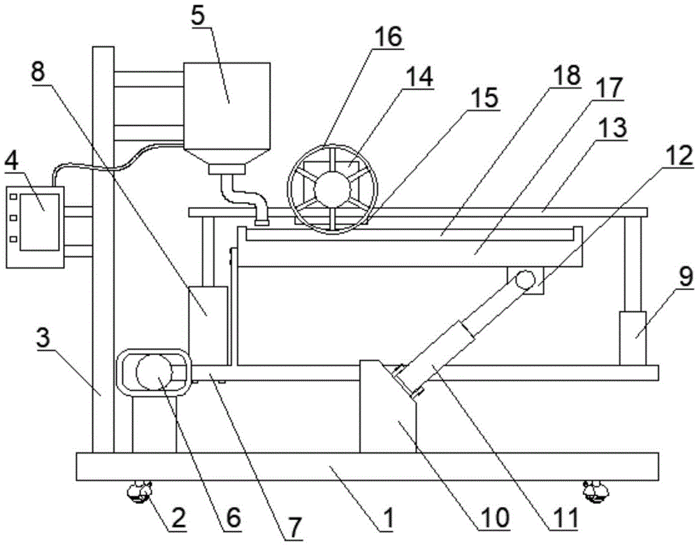
Fig. 1 is a schematic view of the overall structure of a sludge homogenizing discharging device in a sludge drying tower.
FIG. 2 is a schematic side view of the connection between the driving motor and the transverse plate of the sludge homogenizing discharging device in the sludge drying tower.
FIG. 3 is a schematic diagram of the electrical connection of the electrical equipment of the sludge homogenizing discharging device in the sludge drying tower.
In the figure: 1. a base; 2. the universal wheel can be braked; 3. a vertical plate; 4. an electronic time switch; 5. a discharge pump; 6. a limiting guide wheel; 7. an L-shaped mounting plate; 8. a first hydraulic cylinder; 9. a sleeve; 10. a mounting seat; 11. a second hydraulic cylinder; 12. a fixed block; 13. a transverse plate; 14. a drive motor; 15. a limiting block; 16. a compression roller; 17. a fixed table; 18. and (4) an equalizing groove.
Detailed Description
In order to make the technical means, creation features, achievement purposes and functions of the present invention easy to understand, the present invention is further described below with reference to the following embodiments.
As shown in figures 1-3, a sludge homogenizing discharging device in a sludge drying tower comprises a base 1, a first hydraulic cylinder 8 and a second hydraulic cylinder 11, wherein the second hydraulic cylinder 11 is installed on the top of the base 1 through an installation seat 10 and a screw, a vertical plate 3 is installed on the other end of the top of the base 1 through a fixing groove, a vertical plate is welded at one end of the vertical plate 3, an annular limiting block is welded at the top of the vertical plate, a limiting guide wheel 6 is sleeved on the inner side of the annular limiting block, a T-shaped installation plate 7 is welded at one end of the limiting guide wheel 6, a sleeve 9 is installed at one end of the top of the T-shaped installation plate 7 through an installation groove, the first hydraulic cylinder 8 is installed at the other end of the top of the T-shaped installation plate 7 through a screw, a transverse plate 13 is connected with the power output end of the first hydraulic, fixed block 12 is welded to fixed station 17 bottom one end, power take off end one side of second pneumatic cylinder 11 is in fixed block 12 one side through axis of rotation, diaphragm 13 one side is provided with driving motor 14, driving motor 14's power take off end is connected with gyro wheel and the gyro wheel is located the rolling slot that diaphragm 13 top was seted up, gyro wheel one end is connected with compression roller 16 and compression roller 16 through the connecting rod and is located homogenization groove 18 upper end, electronic time switch 4 is installed through the connecting rod to 3 one end of riser, unloading pump 5 is installed through the dead lever in 3 top one side of riser.
Wherein, the sleeve 9 is internally sleeved with a loop bar, and the top of the loop bar is welded at one end of the bottom of the transverse plate 13.
In this embodiment, as shown in fig. 2, the sleeve rod sleeved in the sleeve 9 is convenient to move synchronously when the power output end of the first hydraulic cylinder 8 drives the transverse plate 13 to move.
A limiting block 15 is welded on one side of the bottom end of the driving motor 14, and the limiting block 15 is sleeved in a limiting groove formed in the bottom end of the transverse plate 13.
In this embodiment, as shown in fig. 1, the driving motor 14 is conveniently limited by the movement of the limiting block 15 in the limiting groove at the bottom of the transverse plate 13.
Wherein, the universal wheel 2 that can brake is all installed through the screw at base 1 bottom both ends.
In the embodiment, as shown in fig. 1, the universal wheels 2 capable of braking are utilized, so that a person can conveniently drive the discharging device to move to a proper position for working.
The output end of the electronic timing switch 4 is electrically connected with the input end of the blanking pump 5 through a lead.
In this embodiment, as shown in fig. 1, a person sets a setting value of the electronic time switch 4, and the blanking pump 5 and a circuit of an external power supply are conveniently connected in a timed manner, so that sludge is conveniently blanked in a timed manner, and the labor intensity of personnel management is reduced.
It should be noted that the utility model relates to a sludge homogenizing unloading device in a sludge drying tower, during operation, an external pipeline is used for introducing sludge into a feed inlet of a blanking pump 5, the blanking pump 5 is used for conveniently unloading the sludge into a homogenizing groove 18 at the top of a fixed platform 17, the sludge is unloaded into the homogenizing groove 18, personnel set a set value of an electronic timing switch 4, the circuit of the blanking pump 5 and an external power supply is conveniently and timely connected, thereby the sludge is conveniently and timely unloaded, the labor intensity of personnel management is reduced, a second hydraulic cylinder 11 is opened, a power output end conveniently drives one end of the fixed platform 17 to move up and down during operation, thereby the homogenizing groove 18 is conveniently subjected to angle inclination, thereby the sludge is conveniently pre-flattened by gravity before a compression roller 16 flattens the sludge, energy is saved, the parts connected with the fixed platform 17 are synchronously adjusted by the movement and rotation convenience of a limiting block 6 in an annular limiting block when the angle of the fixed platform 17 is changed, the personnel open driving motor 14, the during operation power take off end conveniently drives the gyro wheel and rolls in the rolling groove at diaphragm 13 top, recycle the removal of stopper 15 in the spacing inslot of diaphragm 13 bottom, it is convenient spacing to carry on driving motor 14, drive pressure roller 16 and rotate when the gyro wheel rotates, thereby conveniently carry out the rapid flattening to the mud that gets into in homogenization groove 18, open first pneumatic cylinder 8, the during operation power take off end conveniently drives diaphragm 13 and reciprocates, thereby the height of compression roller 16 is adjusted according to mud thickness to the convenience, be favorable to carrying out better flattening to mud.
The basic principles and the main features of the invention and the advantages of the invention have been shown and described above. It will be understood by those skilled in the art that the present invention is not limited to the above embodiments, and that the foregoing embodiments and descriptions are provided only to illustrate the principles of the present invention without departing from the spirit and scope of the present invention. The scope of the invention is defined by the appended claims and equivalents thereof.