CN211529665U - High-temperature-resistant coaxial cable - Google Patents
High-temperature-resistant coaxial cable Download PDFInfo
- Publication number
- CN211529665U CN211529665U CN202020325047.6U CN202020325047U CN211529665U CN 211529665 U CN211529665 U CN 211529665U CN 202020325047 U CN202020325047 U CN 202020325047U CN 211529665 U CN211529665 U CN 211529665U
- Authority
- CN
- China
- Prior art keywords
- conductor
- coaxial cable
- outer conductor
- resistant coaxial
- central conductor
- Prior art date
- Legal status (The legal status is an assumption and is not a legal conclusion. Google has not performed a legal analysis and makes no representation as to the accuracy of the status listed.)
- Expired - Fee Related
Links
Images

Landscapes
- Communication Cables (AREA)
Abstract
The utility model discloses a high temperature resistant coaxial cable, which comprises an external conductor, wherein the inside of the external conductor is hollow, the left end and the right end of the external conductor are provided with openings, and both ends of the external conductor are formed with threads; a central conductor is arranged in the outer conductor, the left end and the right end of the central conductor are both in a stepped shaft shape, and an insulator and a pressure ring are sequentially arranged at both ends of the central conductor from inside to outside; the press ring is in threaded connection or clamped connection with the central conductor.
Description
Technical Field
The utility model particularly relates to a high temperature resistant coaxial cable.
Background
Cable is a generic term for optical cables, electrical cables, and the like. The cable has a plurality of purposes, is mainly used for controlling installation, connecting equipment, transmitting electric power and other multiple functions, and is a common and indispensable object in daily life;
the following problems exist in the market at present: coaxial connector cable products on the market at present can not satisfy work under high temperature environment, can not satisfy the needs in special high temperature place.
SUMMERY OF THE UTILITY MODEL
The utility model discloses an it is not enough to overcome above-mentioned condition, aims at providing the technical scheme that can solve above-mentioned problem.
A high-temperature-resistant coaxial cable comprises an outer conductor, wherein the inner part of the outer conductor is hollow, openings are formed in the left end and the right end of the outer conductor, and threads are formed at the two ends of the outer conductor; a central conductor is arranged in the outer conductor, the left end and the right end of the central conductor are both in a stepped shaft shape, and an insulator and a pressure ring are sequentially arranged at both ends of the central conductor from inside to outside; the press ring is in threaded connection or clamped connection with the central conductor.
Preferably, the material of the outer conductor is brass tube material.
Preferably, the material of the central conductor is copper material.
Preferably, the material of the pressure ring is copper material.
Preferably, the material of the insulator is ceramic material.
Preferably, the insulator is formed with a plurality of cutouts.
Compared with the prior art, the beneficial effects of the utility model are that: the high-temperature-resistant coaxial cable can resist more than 350 ℃ and can be continuously used; the cable is divided into four parts, an external conductor (a brass pipe material, threads at two ends can be processed in a machine tool, and the cable is convenient to lock with a connector), a central conductor (a copper material is adopted, the shapes of the two ends can be processed in the machine tool, a compression ring (the copper material can be locked or pressed in by the threads), an insulator (a ceramic material, hole digging design is adopted on ceramic according to characteristic impedance requirements), and the requirement of a special high-temperature place can be met.
Additional aspects and advantages of the invention will be set forth in part in the description which follows and, in part, will be obvious from the description, or may be learned by practice of the invention.
Drawings
In order to more clearly illustrate the embodiments of the present invention or the technical solutions in the prior art, the drawings needed to be used in the description of the embodiments or the prior art will be briefly described below, it is obvious that the drawings in the following description are only some embodiments of the present invention, and for those skilled in the art, other drawings can be obtained according to these drawings without inventive exercise.
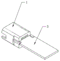
Fig. 1 is a schematic structural diagram of the present invention.
Fig. 2 is a schematic view of the insulator structure of the present invention.
In the figure: an outer conductor 1; an opening 2; a thread 3; a central conductor 4; an insulator 5; and a pressure ring 6.
Detailed Description
The technical solutions in the embodiments of the present invention will be described clearly and completely below, and it should be understood that the described embodiments are only some embodiments of the present invention, but not all embodiments. Based on the embodiments in the present invention, all other embodiments obtained by a person skilled in the art without creative work belong to the protection scope of the present invention.
Referring to fig. 1-2, in an embodiment of the present invention, a high temperature resistant coaxial cable is a design of a high temperature resistant coaxial cable, which includes an outer conductor 1, the outer conductor 1 is hollow, and has openings 2 at left and right ends, and threads 3 are formed at two ends of the outer conductor 1; a central conductor 4 is arranged in the outer conductor 1, the left end and the right end of the central conductor 4 are both in a stepped shaft shape, and an insulator 5 and a pressure ring 6 are sequentially arranged at both ends of the central conductor 4 from inside to outside; the press ring 6 is in threaded connection or clamped connection with the central conductor 4.
Preferably, the material of the outer conductor 1 is brass pipe material.
Preferably, the material of the central conductor 4 is copper material.
Preferably, the material of the pressure ring 6 is copper material.
Preferably, the material of the insulator 5 is ceramic material.
Preferably, the insulator 5 is formed with a plurality of cut-outs, and the cut-outs are formed in the ceramic according to the characteristic impedance requirements.
It is obvious to a person skilled in the art that the invention is not restricted to details of the above-described exemplary embodiments, but that it can be implemented in other specific forms without departing from the spirit or essential characteristics of the invention. The present embodiments are therefore to be considered in all respects as illustrative and not restrictive, the scope of the invention being indicated by the appended claims rather than by the foregoing description, and all changes which come within the meaning and range of equivalency of the claims are therefore intended to be embraced therein.
Claims (6)
1. A high-temperature-resistant coaxial cable is characterized by comprising an outer conductor, wherein the inner part of the outer conductor is hollow, openings are formed at the left end and the right end of the outer conductor, and threads are formed at the two ends of the outer conductor; a central conductor is arranged in the outer conductor, the left end and the right end of the central conductor are both in a stepped shaft shape, and an insulator and a pressure ring are sequentially arranged at both ends of the central conductor from inside to outside; the press ring is in threaded connection or clamped connection with the central conductor.
2. A high temperature resistant coaxial cable as in claim 1, wherein the material of the outer conductor is brass tubing material.
3. A high temperature resistant coaxial cable as in claim 1, wherein the material of the center conductor is copper material.
4. A high temperature resistant coaxial cable as in claim 1, wherein the material of the pressure ring is copper.
5. A high temperature resistant coaxial cable as in claim 1, wherein the insulator is made of a ceramic material.
6. A high temperature resistant coaxial cable as in claim 1, wherein the insulator has a plurality of cutouts formed therein.
Priority Applications (1)
| Application Number | Priority Date | Filing Date | Title |
|---|---|---|---|
| CN202020325047.6U CN211529665U (en) | 2020-03-16 | 2020-03-16 | High-temperature-resistant coaxial cable |
Applications Claiming Priority (1)
| Application Number | Priority Date | Filing Date | Title |
|---|---|---|---|
| CN202020325047.6U CN211529665U (en) | 2020-03-16 | 2020-03-16 | High-temperature-resistant coaxial cable |
Publications (1)
| Publication Number | Publication Date |
|---|---|
| CN211529665U true CN211529665U (en) | 2020-09-18 |
Family
ID=72460281
Family Applications (1)
| Application Number | Title | Priority Date | Filing Date |
|---|---|---|---|
| CN202020325047.6U Expired - Fee Related CN211529665U (en) | 2020-03-16 | 2020-03-16 | High-temperature-resistant coaxial cable |
Country Status (1)
| Country | Link |
|---|---|
| CN (1) | CN211529665U (en) |
-
2020
- 2020-03-16 CN CN202020325047.6U patent/CN211529665U/en not_active Expired - Fee Related
Similar Documents
| Publication | Publication Date | Title |
|---|---|---|
| CN105958242B (en) | Small-sized multicore high-tension connector | |
| CN206135144U (en) | Switching line knot of improvement constructs | |
| CN211529665U (en) | High-temperature-resistant coaxial cable | |
| CN203607625U (en) | Directly-connected zero-insertion electric connector for cable bonding | |
| CN103606786A (en) | Electric direct connector without plugging cable bonding | |
| CN214476624U (en) | High temperature resistance graphite alkene material industry fireproof cable | |
| CN204257860U (en) | A kind of radio frequency connector | |
| CN210957217U (en) | Low-voltage power supply and signal transmission module | |
| CN206558733U (en) | Contact insulator radio frequency connector | |
| CN214506015U (en) | Through hole type self-locking conducting ring assembly | |
| CN211455995U (en) | High-voltage electrical equipment connecting structure | |
| CN221552389U (en) | Quick and reliable electricity-taking assembled coaxial cable branching device | |
| CN220106928U (en) | Cable connector | |
| CN209133793U (en) | A kind of Novel cable line | |
| CN213341409U (en) | Insulation ring main unit conductor joint | |
| CN111146615A (en) | Different diameter long coaxial cable end connection structure | |
| CN217589659U (en) | Shielding type loadable plug-in cable connector | |
| CN212542638U (en) | High-power coaxial fixed attenuator | |
| CN218334390U (en) | Plug-in cable terminal and connecting device thereof | |
| CN215732408U (en) | Electronic wire harness with waterproof and dustproof functions | |
| CN219477191U (en) | Battery signal wire harness | |
| CN218731808U (en) | Cable adaptor | |
| CN217655698U (en) | Wire harness resistant to ultrahigh pressure and high temperature | |
| CN218005329U (en) | Radio frequency management wiring harness system of convenient socket | |
| CN216487365U (en) | Cable with good insulating property |
Legal Events
| Date | Code | Title | Description |
|---|---|---|---|
| GR01 | Patent grant | ||
| GR01 | Patent grant | ||
| CF01 | Termination of patent right due to non-payment of annual fee | ||
| CF01 | Termination of patent right due to non-payment of annual fee |
Granted publication date: 20200918 |