CN211514234U - Novel material tank - Google Patents
Novel material tank Download PDFInfo
- Publication number
- CN211514234U CN211514234U CN201922408040.0U CN201922408040U CN211514234U CN 211514234 U CN211514234 U CN 211514234U CN 201922408040 U CN201922408040 U CN 201922408040U CN 211514234 U CN211514234 U CN 211514234U
- Authority
- CN
- China
- Prior art keywords
- fixed
- pipe
- material tank
- bottom plate
- tank
- Prior art date
- Legal status (The legal status is an assumption and is not a legal conclusion. Google has not performed a legal analysis and makes no representation as to the accuracy of the status listed.)
- Active
Links
Images


Abstract
The utility model belongs to the technical field of the material jar, especially, be a novel material jar, including bottom plate, four fixed columns, four fixing bases, four damping spring, material jar, cover, fixed pipe, heating cabinet, hair-dryer and agitating unit, four the equal fixed mounting of fixed column is in on the bottom plate, four the fixing base is sliding mounting respectively corresponding on the fixed column, four damping spring overlaps respectively and establishes corresponding on the fixed column, damping spring's top and corresponding fixing base fixed connection, damping spring's bottom with bottom plate fixed connection, material jar fixed mounting is four on the fixing base, the cover fixed mounting be in on the material jar, the heating cabinet fixed mounting be in the top of bottom plate, fixed pipe fixed mounting be in the top of heating cabinet. The utility model relates to a rationally, conveniently remove, be convenient for to material even heating and stirring.
Description
Technical Field
The utility model relates to a material tank technical field especially relates to a novel material tank.
Background
The material tank is a container for producing materials, the materials need to be stirred when being placed in the material tank, and meanwhile, some materials need to be heated and stirred during production.
However, in the prior art, the material tank has a single function, can only stir materials independently, cannot perform heating and stirring treatment, and is inconvenient to move, and therefore, the novel material tank is provided.
SUMMERY OF THE UTILITY MODEL
The utility model aims at solving the defects existing in the prior art and providing a novel material tank.
In order to achieve the above purpose, the utility model adopts the following technical scheme: a novel material tank comprises a bottom plate, four fixing columns, four fixing seats, four damping springs, a material tank, a tank cover, a fixing pipe, a heating box, a blower and a stirring device, wherein the four fixing columns are all fixedly arranged on the bottom plate, the four fixing seats are respectively arranged on the corresponding fixing columns in a sliding mode, the four damping springs are respectively sleeved on the corresponding fixing columns, the top end of the damping spring is fixedly connected with the corresponding fixed seat, the bottom end of the damping spring is fixedly connected with the bottom plate, the material tank is fixedly arranged on the four fixing seats, the tank cover is fixedly arranged on the material tank, the heating box is fixedly arranged at the top of the bottom plate, the fixed tube is fixedly arranged at the top of the heating box, the blower is fixedly arranged at the top of the bottom plate, and the stirring device is arranged on the material tank; agitating unit is including setting up the motor at cover top, the output shaft fixed mounting of motor has the rotating tube, the bottom of rotating tube runs through the material jar, fixed mounting has a plurality of stirred tubes on the rotating tube, fixed pipe is kept away from the one end of heating cabinet runs through the material jar and with the rotating tube rotates and is connected.
Preferably, be equipped with electric heating wire in the heating cabinet, be equipped with the air-supply line on the hair-dryer, the one end of air-supply line with heating cabinet fixed connection, the bottom of material jar is equipped with row material pipe, arrange and be equipped with the valve on the material pipe.
Preferably, the bottom of fixing base has seted up the sliding tray, the top of fixed column extend to in the sliding tray that corresponds and with the inner wall sliding connection of sliding tray, the equal fixed mounting in both sides of fixed column has the stopper, the spacing groove has all been seted up to the both sides of sliding tray, the stopper with correspond the inner wall sliding connection of spacing groove.
Preferably, a plurality of air outlets are formed in the stirring pipe, a controller is arranged on one side of the fixing seat, and a temperature sensor is arranged at the bottom of the tank cover.
Preferably, the fixed pipe is sleeved with a bearing, the outer ring of the bearing is fixedly connected with the inner wall of the rotating pipe, the inner wall of the rotating pipe is provided with a sealing ring, and the sealing ring is connected with the fixed pipe in a rotating and sealing manner.
Preferably, a protection box is fixedly installed at the top of the tank cover, and the motor is fixedly installed in the protection box.
Compared with the prior art, the beneficial effects of the utility model are that: can play absorbing effect through damping spring, be convenient for heat the material through fixed pipe, heating cabinet, hair-dryer and electric heating wire, be convenient for carry out even stirring to the material in the material jar through rabbling mechanism, through temperature sensor and controller, be convenient for control the temperature in the material jar to be convenient for heat the stirring to the material of difference and handle, the utility model relates to a rationally, conveniently remove, be convenient for to material even heating and stirring.
Drawings
Fig. 1 is a schematic structural view of the present invention;
FIG. 2 is a schematic sectional view of the present invention;
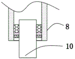
FIG. 3 is an enlarged view of the portion A shown in FIG. 2;
fig. 4 is a schematic view illustrating a coupling structure of the rotating pipe and the fixed pipe shown in fig. 2.
In the figure: 1. a base plate; 2. fixing a column; 3. a fixed seat; 4. a damping spring; 5. a material tank; 6. a can lid; 7. a motor; 8. rotating the tube; 9. a stirring pipe; 10. a fixed tube; 11. a heating box; 12. a blower; 13. an electric heating wire; 14. a discharge pipe; 15. and a stirring mechanism.
Detailed Description
The technical solutions in the embodiments of the present invention will be described clearly and completely with reference to the accompanying drawings in the embodiments of the present invention, and it is obvious that the described embodiments are only some embodiments of the present invention, not all embodiments. Based on the embodiments in the present invention, all other embodiments obtained by a person skilled in the art without creative work belong to the protection scope of the present invention.
Referring to fig. 1-4, the present invention provides a technical solution: a novel material tank, which comprises a bottom plate 1, four fixed columns 2, four fixed seats 3, four damping springs 4 and a material tank 5, the device comprises a tank cover 6, a fixed pipe 10, a heating box 11, a blower 12 and a stirring device 15, wherein four fixed columns 2 are all fixedly arranged on a bottom plate 1, four fixed bases 3 are respectively slidably arranged on the corresponding fixed columns 2, four damping springs 4 are respectively sleeved on the corresponding fixed columns 2, the top ends of the damping springs 4 are fixedly connected with the corresponding fixed bases 3, the bottom ends of the damping springs 4 are fixedly connected with the bottom plate 1, a material tank 5 is fixedly arranged on the four fixed bases 3, the tank cover 6 is fixedly arranged on the material tank 5, the heating box 11 is fixedly arranged at the top of the bottom plate 1, the fixed pipe 10 is fixedly arranged at the top of the heating box 11, the blower 12 is fixedly arranged at the top of the bottom plate 1, and the stirring device 15; agitating unit 15 is including setting up motor 7 at cover 6 top, and motor 7's output shaft fixed mounting has a rotating tube 8, and material jar 5 is run through to the bottom of rotating tube 8, and fixed mounting has a plurality of agitator tubes 9 on the rotating tube 8, and the one end that fixed pipe 10 kept away from heating cabinet 11 runs through material jar 5 and rotates with rotating tube 8 and be connected.
An electric heating wire 13 is arranged in the heating box 11, an air inlet pipe is arranged on the blower 12, one end of the air inlet pipe is fixedly connected with the heating box 11, a material discharging pipe 14 is arranged at the bottom of the material tank 5, a valve is arranged on the material discharging pipe 14, the material discharging pipe 14 is used for discharging materials, a sliding groove is arranged at the bottom of the fixed seat 3, the top end of the fixed column 2 extends into the corresponding sliding groove and is in sliding connection with the inner wall of the sliding groove, limiting blocks are fixedly arranged at the two sides of the fixed column 2, limiting grooves are arranged at the two sides of the sliding groove, the limiting blocks are in sliding connection with the inner wall of the corresponding limiting grooves, a plurality of air outlet holes are arranged on the stirring pipe 9, a controller is arranged at one side of the fixed seat 3, a temperature sensor is arranged at the bottom of the tank cover 6, a bearing is sleeved on the fixed pipe 10, the outer, the top fixed mounting of cover 6 has the guard box, and motor 7 fixed mounting can play absorbing effect through damping spring 4 in the guard box, is convenient for heat the material through fixed pipe 10, heating cabinet 11, hair-dryer 12 and electric heating wire 13, is convenient for carry out even stirring to the material in material jar 5 through rabbling mechanism 15, through temperature sensor and controller, is convenient for control the temperature in the material jar 5 to be convenient for heat the stirring processing to the material of difference, the utility model relates to a rationally, conveniently remove, be convenient for to material even heating and stirring.
The working principle is as follows: the bottom of the bottom plate 1 is provided with four universal wheels, the universal wheels are provided with foot brakes, the fixed seat 3 is provided with a handrail, and the movement is facilitated through the universal wheels and the handrail; the tank cover 6 is provided with a feed inlet, the feed inlet is provided with a baffle, and the electric heating wire 13, the blower 12, the temperature sensor and the controller form a closed loop through wires;
when the material tank is used, the material tank 5 can be moved by pushing the handrail when the material tank 5 needs to be moved, and the damping effect can be achieved through the damping spring 4 in the moving process;
firstly, materials are added into a material tank 5 through a feeding port, after the materials are fed, a baffle plate is covered, then a motor 7 is started, an output shaft of the motor 7 drives a rotating pipe 8 to rotate, the rotating pipe 8 drives a plurality of stirring pipes 9 to rotate, and the materials in the material tank 5 are uniformly stirred through the stirring pipes 9;
meanwhile, when the materials need to be heated, the controller controls the electric heating wire 13 and the blower 12 to work, the blower 12 sends air heated by the electric heating wire 13 into the rotating pipe 8 through the fixed pipe 10, and finally the air flows out through the plurality of air outlets on the stirring pipe 9 to uniformly heat the materials, so that the materials are better heated and stirred, and meanwhile, the damping spring 4 can play an effective damping effect when in work;
when the temperature sensor detects that the temperature is higher than the required temperature, the controller controls the blower 12 and the electric heating wire 13 to stop operating.
It should be noted that the device structure and the accompanying drawings of the present invention mainly describe the principle of the present invention, and in the technology of this design principle, the settings of the power mechanism, the power supply system, the control system, etc. of the device are not completely described, and the details of the power mechanism, the power supply system, and the control system can be clearly known on the premise that those skilled in the art understand the principle of the present invention.
The above, only be the concrete implementation of the preferred embodiment of the present invention, but the protection scope of the present invention is not limited thereto, and any person skilled in the art is in the technical scope of the present invention, according to the technical solution of the present invention and the utility model, the concept of which is equivalent to replace or change, should be covered within the protection scope of the present invention.
Claims (6)
1. A novel material jar which characterized in that: the material tank comprises a bottom plate (1), four fixed columns (2), four fixed seats (3), four damping springs (4), a material tank (5), a tank cover (6), a fixed pipe (10), a heating box (11), a blower (12) and a stirring device (15), wherein the four fixed columns (2) are all fixedly arranged on the bottom plate (1), the four fixed seats (3) are respectively and slidably arranged on the corresponding fixed columns (2), the four damping springs (4) are respectively sleeved on the corresponding fixed columns (2), the top ends of the damping springs (4) are fixedly connected with the corresponding fixed seats (3), the bottom ends of the damping springs (4) are fixedly connected with the bottom plate (1), the material tank (5) is fixedly arranged on the four fixed seats (3), and the tank cover (6) is fixedly arranged on the material tank (5), the heating box (11) is fixedly arranged at the top of the bottom plate (1), the fixed pipe (10) is fixedly arranged at the top of the heating box (11), the blower (12) is fixedly arranged at the top of the bottom plate (1), and the stirring device (15) is arranged on the material tank (5);
agitating unit (15) are including setting up motor (7) at cover (6) top, the output shaft fixed mounting of motor (7) has rotating tube (8), the bottom of rotating tube (8) runs through material jar (5), fixed mounting has a plurality of stirred tubes (9) on rotating tube (8), fixed pipe (10) are kept away from the one end of heating cabinet (11) is run through material jar (5) and with rotating tube (8) rotate and are connected.
2. The novel material tank of claim 1, characterized in that: be equipped with electric heating wire (13) in heating cabinet (11), be equipped with the air-supply line on hair-dryer (12), the one end of air-supply line with heating cabinet (11) fixed connection, the bottom of material jar (5) is equipped with row material pipe (14), be equipped with the valve on arranging material pipe (14).
3. The novel material tank of claim 1, characterized in that: the sliding groove has been seted up to the bottom of fixing base (3), the top of fixed column (2) extend to the sliding groove that corresponds in and with the inner wall sliding connection of sliding groove, the equal fixed mounting in both sides of fixed column (2) has the stopper, the spacing groove has all been seted up to the both sides of sliding groove, the stopper with correspond the inner wall sliding connection of spacing groove.
4. The novel material tank of claim 1, characterized in that: a plurality of air outlets are formed in the stirring pipe (9), a controller is arranged on one side of the fixing seat (3), and a temperature sensor is arranged at the bottom of the tank cover (6).
5. The novel material tank of claim 1, characterized in that: the fixed pipe (10) is sleeved with a bearing, the outer ring of the bearing is fixedly connected with the inner wall of the rotating pipe (8), a sealing ring is arranged on the inner wall of the rotating pipe (8), and the sealing ring is connected with the fixed pipe (10) in a rotating and sealing mode.
6. The novel material tank of claim 1, characterized in that: the top of cover (6) is fixed with the guard box, motor (7) fixed mounting is in the guard box.
Priority Applications (1)
| Application Number | Priority Date | Filing Date | Title |
|---|---|---|---|
| CN201922408040.0U CN211514234U (en) | 2019-12-27 | 2019-12-27 | Novel material tank |
Applications Claiming Priority (1)
| Application Number | Priority Date | Filing Date | Title |
|---|---|---|---|
| CN201922408040.0U CN211514234U (en) | 2019-12-27 | 2019-12-27 | Novel material tank |
Publications (1)
| Publication Number | Publication Date |
|---|---|
| CN211514234U true CN211514234U (en) | 2020-09-18 |
Family
ID=72467232
Family Applications (1)
| Application Number | Title | Priority Date | Filing Date |
|---|---|---|---|
| CN201922408040.0U Active CN211514234U (en) | 2019-12-27 | 2019-12-27 | Novel material tank |
Country Status (1)
| Country | Link |
|---|---|
| CN (1) | CN211514234U (en) |
Cited By (1)
| Publication number | Priority date | Publication date | Assignee | Title |
|---|---|---|---|---|
| CN112337145A (en) * | 2020-10-09 | 2021-02-09 | 南通特乃博高新材料有限公司 | Precipitation device for producing aluminum oxide powder |
-
2019
- 2019-12-27 CN CN201922408040.0U patent/CN211514234U/en active Active
Cited By (1)
| Publication number | Priority date | Publication date | Assignee | Title |
|---|---|---|---|---|
| CN112337145A (en) * | 2020-10-09 | 2021-02-09 | 南通特乃博高新材料有限公司 | Precipitation device for producing aluminum oxide powder |
Similar Documents
| Publication | Publication Date | Title |
|---|---|---|
| CN104596216B (en) | The drying machine of plastic bottle sheet | |
| CN211514234U (en) | Novel material tank | |
| CN106732254A (en) | A kind of multifunctional reaction still for preparing vinylite | |
| CN110131885A (en) | A kind of controllable warm type energy-saving water heater | |
| CN210820367U (en) | Plastic hot melting treatment equipment for plastic mold production | |
| CN208517299U (en) | A kind of microorganism fertilizer bacterium fermentation batches device | |
| CN205164731U (en) | High -efficient reation kettle convenient to remove | |
| CN205269629U (en) | Raw materials recycle mixing type reation kettle | |
| CN204208551U (en) | A kind of chemical industry liquid reactions still | |
| CN206326761U (en) | Energy-efficient polyurethane sheet mixer | |
| CN204911493U (en) | Rapid mixing reation kettle | |
| CN106824029A (en) | It is a kind of with the polyethylene production equipment being uniformly heated with attemperator | |
| CN206315794U (en) | It is a kind of that there is the uniform heated polyethylene production equipment with attemperator | |
| CN206701279U (en) | A kind of novel and multifunctional reaction kettle device | |
| CN104984710A (en) | Horizontal reaction device used for preparing molecule sieve catalysts and preparation method | |
| CN201386154Y (en) | Heating system of polymer fiber intelligent heat setting machine | |
| CN211087022U (en) | Full-automatic reactor temperature control system | |
| CN212309588U (en) | Production device of perfluoroalkyl alkoxy silane | |
| CN209501649U (en) | A kind of chemistry Minute Organic Synthesis heating device | |
| CN219441200U (en) | Device for improving tail gas purification efficiency | |
| CN219502736U (en) | Improve reation kettle of chlorinated polyethylene yield | |
| CN210229875U (en) | Horizontal mixer | |
| CN217226237U (en) | Phenolic molding plastic mixing structure | |
| CN207085870U (en) | A kind of new molten structure of reactor of acid | |
| CN218249795U (en) | Constant temperature agitating unit is used in microbial inoculant production |
Legal Events
| Date | Code | Title | Description |
|---|---|---|---|
| GR01 | Patent grant | ||
| GR01 | Patent grant |