CN211501719U - Floating ball valve with low torque and smooth opening and closing - Google Patents
Floating ball valve with low torque and smooth opening and closing Download PDFInfo
- Publication number
- CN211501719U CN211501719U CN201922119028.8U CN201922119028U CN211501719U CN 211501719 U CN211501719 U CN 211501719U CN 201922119028 U CN201922119028 U CN 201922119028U CN 211501719 U CN211501719 U CN 211501719U
- Authority
- CN
- China
- Prior art keywords
- valve
- valve rod
- thrust
- ball
- floating ball
- Prior art date
- Legal status (The legal status is an assumption and is not a legal conclusion. Google has not performed a legal analysis and makes no representation as to the accuracy of the status listed.)
- Active
Links
Images

Abstract
The utility model discloses a low-torque and smooth-switching floating ball valve, which has the technical scheme main points that the low-torque and smooth-switching floating ball valve comprises a valve body, a valve rod and a ball body, wherein the valve body is provided with an inflow channel and an outflow channel, a valve cavity is arranged between the inflow channel and the outflow channel, the ball body is arranged in the valve cavity, the valve body is also provided with a valve rod hole, one end of the valve rod penetrates out of the valve body hole to be connected with a driving device, and the other end of the valve rod is spliced with a flat notch on the ball body to form a circumferential positioning connection structure; the valve rod is provided with an inclined plane flange part close to the end of the ball body, and a thrust device is arranged between the valve rod and the thrust port of the valve rod hole to form a valve rod sealing structure; the utility model discloses simple structure, manufacturing process is simple, and the leakproofness is good, and the moment of torsion is low, the switch is smooth, long service life.
Description
Technical Field
The utility model relates to a mechanical valve field, more specifically the floating ball valve that relates to a low moment of torsion and switch are smooth that says so.
Background
In the prior art, the ball valve is mainly used for cutting, distributing and changing the flowing direction of a medium, the floating ball valve in the prior art mainly comprises a valve body, a ball body, a valve rod, a wrench and the like, the general prior art has the problems of complicated structure, large volume, complicated manufacturing process, large abrasion of a sealing surface, short service life and the like, at present, the Chinese utility model with the publication number of CN205226446U discloses a low-torque ball valve with a thrust pad, although the ball valve has the advantages that the wedge-shaped thrust pad is arranged, the contact inclined plane of the thrust pad and the stuffing box has the angle difference of 2 degrees, the problem that the valve rod rotates to scratch with the stuffing box is solved, the friction effect is reduced, meanwhile, the sealing function can be achieved, however, the thrust pad is in contact with the filler, the sealing function can not be achieved under the condition of small thrust, the ball valve is large in maintenance workload, short in service life and large in power loss.
SUMMERY OF THE UTILITY MODEL
Not enough to prior art exists, the utility model aims to provide a low moment of torsion and smooth ball valve that floats of switch, this low moment of torsion and smooth ball valve that floats of switch, simple structure, manufacturing process is simple, and the leakproofness is good, and the moment of torsion is low, the switch is smooth, long service life.
In order to achieve the above purpose, the utility model provides a following technical scheme:
a low-torque floating ball valve with smooth opening and closing comprises a valve body, a valve rod and a ball body, wherein an inflow channel and an outflow channel are arranged on the valve body, a valve cavity is arranged between the inflow channel and the outflow channel, and the ball body is arranged in the valve cavity; the valve rod is provided with an inclined plane flange part near the ball body end, and a thrust device is arranged between the valve rod and the thrust port of the valve rod hole to form a valve rod sealing structure.
Technical scheme more than adopting, the utility model has the advantages of it is following:
the valve body of the utility model is also provided with a valve rod hole, one end of the valve rod penetrates out of the valve body hole to be connected with the driving device, and the other end is connected with the flat notch on the ball body in a plugging way to form a circumferential positioning connection structure, thus having simple structure and convenient operation; the valve rod is close to the spheroid end and is equipped with inclined plane flange portion, and the thrust mouth in valve rod hole between be equipped with thrust device and constitute valve rod seal structure, thrust device has increased the leakproofness between valve body and the valve rod, reduces the outer possibility of leaking of ball valve.
Further, the thrust device comprises a thrust washer and an O-shaped ring; the thrust gasket is an angular surface with the contact end of the inclined plane flange part of the valve rod, an annular groove is arranged at the joint of the thrust gasket and the outer wall of the shaft diameter of the valve rod, and an O-shaped ring is arranged in the annular groove.
Technical scheme more than adopting, the utility model has the advantages of it is following:
the contact end of the thrust gasket and the inclined plane flange part of the valve rod is an angle surface, and the angle surface improves the sealing property between the thrust gasket and the valve rod; the utility model discloses be equipped with an annular groove with the axle footpath outer wall junction of valve rod, be equipped with O type circle in the annular groove, the setting of O type circle further promotes the leakproofness of valve body and valve rod.
Further, the angle surface is 30-45 degrees.
Technical scheme more than adopting, the utility model has the advantages of it is following:
the angle surface of the utility model is 30 degrees to 45 degrees, so that the valve rod can be sealed under smaller thrust.
Furthermore, two pressure reverse punching holes are formed in the valve rod, and springs are embedded in the pressure reverse punching holes.
Technical scheme more than adopting, the utility model has the advantages of it is following:
when the floating ball valve operates, the ball body is prone, the valve rod can be abraded, the valve rod rotates, the valve body can also be abraded, two pressure reverse punching holes are formed in the valve rod, the spring is arranged in the pressure reverse punching holes in an embedded mode, the spring has reverse thrust, abrasion of the valve rod and the valve body can be reduced, and the sealing performance between the valve rod and the valve body and between the valve rod and the ball body can be further enhanced.
Drawings
The present invention will be further explained with reference to the drawings and examples.
Fig. 1 is a schematic view of a floating ball valve with low torque and smooth opening and closing.
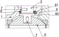
Fig. 2 is an enlarged schematic view at a.
Reference numerals: 1. a valve body; 3. a valve stem; 4. a valve cavity; 5. a sphere; 7. pressure reverse punching; 8. a thrust washer; 81. an annular groove; 82. an angular surface; 9. and an O-shaped ring.
Detailed Description
As shown in fig. 1, a floating ball valve with low torque and smooth opening and closing comprises a valve body 1, a valve rod 3 and a ball body 5, wherein an inflow channel and an outflow channel are arranged on the valve body 1, a valve cavity 4 is arranged between the inflow channel and the outflow channel, the ball body 5 is arranged in the valve cavity 4, a valve rod hole is also arranged on the valve body 1, one end of the valve rod 3 penetrates through the valve body hole to be connected with a driving device, and the other end of the valve rod is connected with a flat notch on the ball body 5 in an inserting manner to form a circumferential positioning connection; wherein, the valve rod 3 is provided with an inclined plane flange part near the end of the ball body 5, and a thrust device is arranged between the inclined plane flange part and the thrust opening of the valve rod hole to form a valve rod sealing structure.
Through the arrangement, the valve body 1 of the utility model is also provided with a valve rod hole, one end of the valve rod 3 penetrates out of the valve body hole to be connected with the driving device, and the other end is connected with the flat notch on the ball body 5 in a plugging way to form a circumferential positioning connection structure, so that the structure is simple and the operation is convenient; the utility model discloses valve rod 3 is close to 5 ends of spheroid and is equipped with inclined plane flange portion, and the thrust mouth in valve rod hole between be equipped with thrust device and constitute valve rod seal structure, thrust device has increased the leakproofness between valve body 1 and the valve rod 3, reduces the outer possibility of leaking of ball valve.
As shown in fig. 2, the thrust device comprises a thrust washer 8 and an O-ring 9; the contact end of the thrust washer 8 and the inclined plane flange part of the valve rod 3 is an angular surface 82, an annular groove 81 is arranged at the joint of the thrust washer and the shaft diameter outer wall of the valve rod 3, and an O-shaped ring 9 is arranged in the annular groove 81; the angular surface 82 is 30-45 degrees; two pressure reverse punching holes 7 are arranged on the valve rod 3, and springs are embedded in the pressure reverse punching holes 7.
Through the arrangement, the contact end of the thrust washer 8 and the inclined plane flange part of the valve rod 3 is the angle surface 82, and the angle surface 82 improves the sealing property between the thrust washer 8 and the valve rod 3; the joint of the shaft diameter outer wall of the valve rod 3 is provided with an annular groove 81, an O-shaped ring 9 is arranged in the annular groove 81, and the arrangement of the O-shaped ring 9 further improves the sealing performance of the valve body 1 and the valve rod 3; the angle surface 82 of the utility model is 30 degrees to 45 degrees, so that the valve rod 3 can realize sealing under smaller thrust; floating ball valve is when the function, and spheroid 5 is at the photovoltaic, and valve rod 3 can produce wearing and tearing, and valve rod 3 rotates, and valve body 1 also can produce wearing and tearing, is provided with two pressures on the valve rod 3 and anti-punches a hole 7, and the setting of embedding spring in the pressure anti-punches a hole 7, and the spring has the thrust that turns back, can reduce the wearing and tearing of valve rod 3 and valve body 1, can also further strengthen the leakproofness between valve rod 3 and valve body 1 and valve rod 3 and spheroid 5.
Claims (4)
1. A floating ball valve with low torque and smooth opening and closing comprises a valve body (1), a valve rod (3) and a ball body (5), wherein an inflow channel and an outflow channel are arranged on the valve body (1), a valve cavity (4) is arranged between the inflow channel and the outflow channel, and the ball body (5) is arranged in the valve cavity (4), and is characterized in that a valve rod hole is also arranged on the valve body (1), one end of the valve rod (3) penetrates out of the valve body hole to be connected with a driving device, and the other end of the valve rod is connected with a flat notch on the ball body (5) in an inserting manner to form a circumferential positioning connection structure; the valve rod (3) is provided with an inclined plane flange part at the end close to the ball body (5), and a thrust device is arranged between the inclined plane flange part and the thrust port of the valve rod hole to form a valve rod sealing structure.
2. A low torque and open-flow floating ball valve according to claim 1 wherein said thrust means comprises a thrust washer (8) and an O-ring (9); the thrust washer (8) and the inclined plane flange part contact end of the valve rod (3) are angular surfaces (82), an annular groove (81) is arranged at the joint of the thrust washer and the shaft diameter outer wall of the valve rod (3), and an O-shaped ring (9) is arranged in the annular groove (81).
3. A low torque and smooth opening and closing floating ball valve according to claim 2 wherein said angular surface (82) is between 30 ° and 45 °.
4. A low torque and smooth opening and closing floating ball valve according to claim 2, characterized in that two pressure back punch holes (7) are provided on the valve stem (3), and a spring is embedded in the pressure back punch holes (7).
Priority Applications (1)
| Application Number | Priority Date | Filing Date | Title |
|---|---|---|---|
| CN201922119028.8U CN211501719U (en) | 2019-12-02 | 2019-12-02 | Floating ball valve with low torque and smooth opening and closing |
Applications Claiming Priority (1)
| Application Number | Priority Date | Filing Date | Title |
|---|---|---|---|
| CN201922119028.8U CN211501719U (en) | 2019-12-02 | 2019-12-02 | Floating ball valve with low torque and smooth opening and closing |
Publications (1)
| Publication Number | Publication Date |
|---|---|
| CN211501719U true CN211501719U (en) | 2020-09-15 |
Family
ID=72412586
Family Applications (1)
| Application Number | Title | Priority Date | Filing Date |
|---|---|---|---|
| CN201922119028.8U Active CN211501719U (en) | 2019-12-02 | 2019-12-02 | Floating ball valve with low torque and smooth opening and closing |
Country Status (1)
| Country | Link |
|---|---|
| CN (1) | CN211501719U (en) |
-
2019
- 2019-12-02 CN CN201922119028.8U patent/CN211501719U/en active Active
Similar Documents
| Publication | Publication Date | Title |
|---|---|---|
| CN205173525U (en) | Submarine pipeline pair gate valve | |
| CN211501719U (en) | Floating ball valve with low torque and smooth opening and closing | |
| CN201582409U (en) | Spherical sealing butterfly valve provided with valve plate coated with rubber layer | |
| CN209130354U (en) | A kind of pipeline jointing construction of quick-clamping | |
| CN201209674Y (en) | Two-way flexible sealed butterfly valve | |
| CN203051797U (en) | Self-adaption elastic valve seat varying with pressure | |
| CN210372110U (en) | Eccentric half ball valve | |
| CN202493770U (en) | Follow-up shaft seal ring structure of butterfly valve | |
| CN207975265U (en) | A kind of bidirectional sealed butterfly valve using fluoroplastics valve seat construction | |
| CN207975268U (en) | Using the bidirectional sealed butterfly valve of rubber valve seat structure | |
| CN202327196U (en) | Hard seal ball valve | |
| CN207364318U (en) | A kind of structure of high sealing liquid flow control ball valve easy to connection | |
| CN205479466U (en) | Unsteady ball valve seating structure | |
| CN219082377U (en) | Novel valve shaft anti-falling structure | |
| CN205207705U (en) | Disk seat of eccentric butterfly valve | |
| CN210949998U (en) | Leak-proof ball valve | |
| CN214367835U (en) | Wafer type high-temperature butterfly valve | |
| CN211852831U (en) | Bidirectional sealing butterfly valve | |
| CN212616456U (en) | Ball valve seat hole structure | |
| CN212616372U (en) | High leakproofness butterfly valve | |
| CN211715818U (en) | Duplex all-welded eccentric half-ball valve | |
| CN203940000U (en) | A kind of Novel electric stop valve | |
| CN211649123U (en) | Low-torque floating ball valve with sectional type transition spherical surface | |
| CN212203158U (en) | Corrosion-resistant butterfly valve with good sealing performance | |
| CN203686172U (en) | High pound grade flexible seal safety butterfly valve |
Legal Events
| Date | Code | Title | Description |
|---|---|---|---|
| GR01 | Patent grant | ||
| GR01 | Patent grant |