CN211500128U - Self-service equipment electronic door device - Google Patents
Self-service equipment electronic door device Download PDFInfo
- Publication number
- CN211500128U CN211500128U CN201921611317.3U CN201921611317U CN211500128U CN 211500128 U CN211500128 U CN 211500128U CN 201921611317 U CN201921611317 U CN 201921611317U CN 211500128 U CN211500128 U CN 211500128U
- Authority
- CN
- China
- Prior art keywords
- lock
- bearing
- cam
- steering engine
- fixedly connected
- Prior art date
- Legal status (The legal status is an assumption and is not a legal conclusion. Google has not performed a legal analysis and makes no representation as to the accuracy of the status listed.)
- Active
Links
Images


Abstract
A self-service equipment electronic door device comprises an electric lock mechanism and a movable door mechanism; the electric lock mechanism is provided with a lock seat, a cam, a push rod, a linear bearing, a steering engine and a lock tongue, wherein the steering engine is fixedly connected with the lock seat, the steering engine is connected with the cam and drives the cam to rotate, the cam is provided with a convex column, a bearing is arranged on the convex column, the inner diameter of the bearing is the same as the outer diameter of the convex column, the bearing is sleeved on the convex column, the push rod is provided with a convex part and a rectangular through groove, the bearing is located in the rectangular through groove, the convex part is fixedly connected with the lock tongue, the inner diameter of the linear bearing is the same as the outer diameter of the lock tongue, and the lock tongue penetrates through the linear bearing. The utility model discloses a steering wheel is as driving power structure, realizes locking automatically and automatic unblock through the steering wheel positive and negative commentaries on classics. The device has simple structure, stability and reliability, and the steering engine has low cost.
Description
Technical Field
The utility model relates to a sell machine accessory field by oneself, especially a self-service equipment electronic door device.
Background
The self-service vending machine is a common commercial automatic device, is not limited by time and place, can save manpower and facilitate transaction, and is a brand new commercial retail form, so the self-service vending machine is also called a micro supermarket which is operated for 24 hours. Among the prior art, some sell the machine by oneself and go up to get the goods storehouse and be provided with electronic automatic lock. The electronic automatic locks applied to the self-service vending machine have various types, but most of the electronic automatic locks use a micro direct current motor and a spring as power to be switched on and off. Such electronic automatic locks tend to be costly, expensive and mechanically unstable.
SUMMERY OF THE UTILITY MODEL
In order to overcome the above disadvantages of the prior art, the present invention provides a self-service electronic door device.
The utility model provides a technical scheme that its technical problem adopted is: a self-service equipment electronic door device comprises an electric lock mechanism and a movable door mechanism;
the electric lock mechanism is provided with a lock seat, a cam, a push rod, a linear bearing, a steering engine and a lock tongue, wherein the steering engine is fixedly connected with the lock seat, the steering engine is connected with the cam and drives the cam to rotate, the cam is provided with a convex column, a bearing is arranged on the convex column, the inner diameter of the bearing is the same as the outer diameter of the convex column, the bearing is sleeved on the convex column, the push rod is provided with a convex part and a rectangular through groove, the bearing is located in the rectangular through groove, the convex part is fixedly connected with the lock tongue, the inner diameter of the linear bearing is the same as the outer diameter of the lock tongue, and the lock tongue penetrates through the linear bearing.
The movable door mechanism is provided with a goods-taking plate, a magnet, an iron column and a movable door, the lock seat is fixed on the goods-taking plate, the goods-taking plate is provided with a door frame, the magnet is located on the inner side of the door frame, a movable door shaft is arranged at the top end of the door frame, the door shaft is connected with the movable door, the iron column is located at the bottom of the movable door, and one side of the movable door is provided with a lock hole.
As a further improvement of the utility model: the lock is characterized in that the lock seat is provided with a separation blade base and a switch separation blade, the separation blade base is fixedly connected with the lock seat, the switch separation blade is connected with the bottom of the push rod, and the switch separation blade is positioned on the separation blade base and is attached to the top surface of the separation blade base.
As a further improvement of the utility model: the goods taking plate is provided with a second switch blocking piece, and the second switch blocking piece is fixedly connected with one end of the movable door shaft.
As a further improvement of the utility model: the goods taking device is characterized by further comprising a driving circuit, a travel switch and a second travel switch, wherein the travel switch is fixedly connected with the lock seat, the second travel switch is fixed on the goods taking plate, and the driving circuit is electrically connected with the steering engine.
As a further improvement of the utility model: the electric lock mechanism is provided with a left electric lock mechanism and a right electric lock mechanism, and the left side and the right side of the door frame are symmetrically arranged.
Compared with the prior art, the beneficial effects of the utility model are that: the steering engine is used as a driving force structure, and automatic locking and automatic unlocking are realized through forward and reverse rotation of the steering engine. The device has simple structure, stability and reliability, and the steering engine has low cost.
Drawings
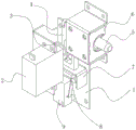
Fig. 1 is a schematic structural view of the electric lock mechanism of the present invention.
Fig. 2 is a schematic structural diagram of the push rod of the present invention.
Fig. 3 is an assembly schematic diagram of the steering engine, the cam and the bearing of the present invention.
Fig. 4 is the unlocking operation schematic diagram of the electric lock of the present invention.
Fig. 5 is a schematic view of the locking operation of the electric lock of the present invention.
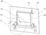
Fig. 6 is the structure schematic diagram of the electric lock mechanism and the movable door mechanism of the present invention.
Fig. 7 is a schematic structural view of the movable door of the present invention.
Fig. 8 is an enlarged view of the circled portion in fig. 6.
Description of the drawings: 1-lock seat, 2-steering engine, 3-cam, 4-push rod, 5-lock tongue, 6-linear bearing, 7-switch baffle, 8-baffle base, 9-travel switch, 11-rectangular through groove, 12-convex part, 21-bearing, 31-magnet, 32-iron column, 33-movable door, 34-second travel switch, 35-second switch baffle, 36-cargo compartment plate, 37-movable door shaft, 38-door frame and 44-lock hole.
Detailed Description
The invention will now be further described with reference to the accompanying drawings, in which:
referring to fig. 1 to 8, in an embodiment of the present invention, a self-service device electronic door device includes an electric lock mechanism and a movable door mechanism;
the electric lock mechanism is provided with a lock base 1, a cam 3, a push rod 4, a linear bearing 6, a steering engine 2 and a lock tongue 5, the steering engine 2 is fixedly connected with the lock base 1, the steering engine 2 is connected with the cam 3 and drives the cam 3 to rotate, the cam 3 is provided with a convex column, a bearing 21 is arranged on the convex column, the inner diameter of the bearing 21 is the same as the outer diameter of the convex column, the bearing 21 is sleeved on the convex column, the push rod 4 is provided with a convex part 12 and a rectangular through groove 11, the bearing 21 is positioned in the rectangular through groove 11, the convex part 12 is fixedly connected with the lock tongue 5, the linear bearing 6 is fixedly connected with the lock base 1, the inner diameter of the linear bearing is the same as the outer diameter of the lock tongue 5, and the lock tongue.
Referring to fig. 5, when the electric lock mechanism is locked, the steering engine 2 drives the cam 3 and the bearing 21 to rotate forward. The outer ring wall of the bearing 21 is attached to the inner wall of the push rod rectangular through groove 11, and the bearing 21 pushes the push rod 4 to move through the rotating acting force of the cam 3. Because the top of the push rod 4 is connected with the lock tongue 5, the lock tongue 5 is positioned in the linear bearing 6, the linear bearing 6 limits the motion direction of the lock tongue 5, and the push rod 4 pushes the lock tongue 5 to do linear motion along the axial center direction of the lock tongue 5. Before locking, the head of the bolt 5 is positioned in the linear bearing 6, and in the locking process, the bolt 5 moves linearly and extends out to be clamped on the movable door 33, so that the locking process is completed.
Referring to fig. 4, when the electric lock mechanism is unlocked, the steering engine 2 drives the cam 3 and the bearing 21 to rotate reversely. The outer ring wall of the bearing 21 is attached to the inner wall of the push rod rectangular through groove 11, and the bearing 21 pushes the push rod 4 to move through the rotating acting force of the cam 3. Because the top of the push rod 4 is connected with the lock tongue 5, the push rod 4 pulls the lock tongue 5 to do linear motion along the axial center direction of the lock tongue 5. Before unlocking, the head of the bolt 5 is positioned outside the linear bearing 6, in the unlocking process, the bolt 5 retracts by making linear motion, and the bolt 5 is separated from the movable door 33 to finish the unlocking process.
The movable door mechanism is provided with and gets cargo hold board 36, magnet 31, iron prop 32, dodge gate 33, lock seat 1 is fixed in and gets on cargo hold board 36, it is equipped with door frame 38 to get cargo hold board 36, magnet 31 is located door frame 38 is inboard, the door frame 38 is close to the top and is equipped with dodge gate axle 37, dodge gate axle 37 is connected with dodge gate 33, iron prop 32 is located dodge gate 33 bottom, one side of dodge gate 33 is equipped with lockhole 44.
The lock is characterized in that a separation blade base 8 and a switch separation blade 7 are arranged on the lock base 1, the separation blade base 8 is fixedly connected with the lock base 1, the switch separation blade 7 is connected with the bottom of the push rod 4, and the switch separation blade 7 is located on the separation blade base 8 and is attached to the top surface of the separation blade base 8.
One surface of the switch baffle 7 is attached to the top surface of the baffle base 8, and the baffle base 8 is fixed on the lock base 1; the other side of the switch catch 7 is connected with the bottom of the push rod 4, the push rod 4 is fixedly connected with the lock tongue 5, and the lock tongue 5 only moves in a left-right linear mode. Therefore, the switch blocking piece 7 does linear motion on the blocking piece base 8 in the same motion direction as the lock tongue 5 under the transmission action of the rotation of the steering engine 2.
The goods taking plate 36 is provided with a second switch baffle 35. The second switch blocking piece 35 is fixedly connected with one end of the movable door shaft 37.
The automatic locking device further comprises a driving circuit, a travel switch 9 and a second travel switch 34, wherein the travel switch 9 is fixedly connected with the lock seat 1, the second travel switch 34 is fixed on the goods taking bin plate 36, and the driving circuit is electrically connected with the steering engine 2. The driving circuit is a conventional circuit for driving the steering engine 2 to rotate forward and backward.
The electric lock mechanism is provided with a left electric lock mechanism and a right electric lock mechanism, and the left side and the right side of the door frame 38 are symmetrically arranged.
When goods in the vending machine are conveyed into the goods taking bin, the driving circuit controls the electric lock mechanisms on two sides of the door frame 38 to unlock. The two side lock tongues 5 are retracted from the lock holes 44, and the movable door 33 can be opened by the customer's pulling, and then the goods in the warehouse can be taken. After the goods are taken away, the movable door 33 is closed due to the self weight of the movable door 33 and the attraction of the magnet 31 caused by the iron column 32 approaching the magnet 31. While the shutter 33 is closed, the second opening/closing shutter 34 rotates as the shutter shaft 37 rotates. Second switch separation blade 35 collides when pivoted second travel switch 34's contact, second travel switch 34 produces the signal of telecommunication and feeds back to self-service vending machine equipment system, equipment system knows that dodge gate 33 has closed, send the signal extremely drive circuit drive steering wheel 2 locks.
In addition, when the electric lock mechanism performs unlocking operation, the switch catch 7 retracts in the same direction as the latch bolt 5. The switch separation blade 7 collides the contact of the travel switch 9 when retracting, the travel switch 9 generates an electric signal and feeds the electric signal back to the self-service vending machine equipment system, and the equipment system learns that the electric lock is unlocked.
In the description of the present invention, it is to be understood that the terms "top", "bottom", "left" and "left" are used herein,
The directions or positional relationships indicated by "right" and the like are based on the directions or positional relationships shown in the drawings, and are merely for convenience of description of the present invention, and therefore, cannot be understood as limitations on the directions of actual use of the present invention. In conclusion, after the ordinary skilled in the art reads the document of the present invention, according to the present invention, the technical solution and technical concept of the present invention do not need creative mental labor to make other various corresponding transformation schemes, which all belong to the protection scope of the present invention.
Claims (5)
1. The utility model provides a self-service equipment electronic door device which characterized in that: comprises an electric lock mechanism and a movable door mechanism;
the electric lock mechanism is provided with a lock base, a cam, a push rod, a linear bearing, a steering engine and a lock tongue, wherein the steering engine is fixedly connected with the lock base, the steering engine is connected with the cam and drives the cam to rotate, the cam is provided with a convex column, a bearing is arranged on the convex column, the inner diameter of the bearing is the same as the outer diameter of the convex column, the bearing is sleeved on the convex column, the push rod is provided with a convex part and a rectangular through groove, the bearing is positioned in the rectangular through groove, the convex part is fixedly connected with the lock tongue, the linear bearing is fixedly connected with the lock base, the inner diameter of the linear bearing is the same as the outer diameter of the lock tongue;
the movable door mechanism is provided with a goods-taking plate, a magnet, an iron column and a movable door, the lock seat is fixed on the goods-taking plate, the goods-taking plate is provided with a door frame, the magnet is located on the inner side of the door frame, a movable door shaft is arranged at the top end of the door frame, the door shaft is connected with the movable door, the iron column is located at the bottom of the movable door, and one side of the movable door is provided with a lock hole.
2. The self-service device electronic door apparatus of claim 1, wherein: the lock is characterized in that the lock seat is provided with a separation blade base and a switch separation blade, the separation blade base is fixedly connected with the lock seat, the switch separation blade is connected with the bottom of the push rod, and the switch separation blade is positioned on the separation blade base and is attached to the top surface of the separation blade base.
3. The self-service device electronic door apparatus of claim 1, wherein: the goods taking plate is provided with a second switch blocking piece, and the second switch blocking piece is fixedly connected with one end of the movable door shaft.
4. The self-service device electronic door apparatus of claim 1, wherein: the goods taking device is characterized by further comprising a driving circuit, a travel switch and a second travel switch, wherein the travel switch is fixedly connected with the lock seat, the second travel switch is fixed on the goods taking plate, and the driving circuit is electrically connected with the steering engine.
5. The self-service device electronic door apparatus of claim 1, wherein: the electric lock mechanism is provided with a left electric lock mechanism and a right electric lock mechanism, and the left side and the right side of the door frame are symmetrically arranged.
Priority Applications (1)
| Application Number | Priority Date | Filing Date | Title |
|---|---|---|---|
| CN201921611317.3U CN211500128U (en) | 2019-09-26 | 2019-09-26 | Self-service equipment electronic door device |
Applications Claiming Priority (1)
| Application Number | Priority Date | Filing Date | Title |
|---|---|---|---|
| CN201921611317.3U CN211500128U (en) | 2019-09-26 | 2019-09-26 | Self-service equipment electronic door device |
Publications (1)
| Publication Number | Publication Date |
|---|---|
| CN211500128U true CN211500128U (en) | 2020-09-15 |
Family
ID=72405821
Family Applications (1)
| Application Number | Title | Priority Date | Filing Date |
|---|---|---|---|
| CN201921611317.3U Active CN211500128U (en) | 2019-09-26 | 2019-09-26 | Self-service equipment electronic door device |
Country Status (1)
| Country | Link |
|---|---|
| CN (1) | CN211500128U (en) |
-
2019
- 2019-09-26 CN CN201921611317.3U patent/CN211500128U/en active Active
Similar Documents
| Publication | Publication Date | Title |
|---|---|---|
| CN107558830B (en) | Electric suction lock | |
| CN201198687Y (en) | Anti-theft car door lock automatic control device | |
| EP3868599B1 (en) | Battery assembly locking device and automated guided vehicle | |
| CN107246188B (en) | Motor anti-theft lock | |
| CN211500128U (en) | Self-service equipment electronic door device | |
| CN206665280U (en) | A kind of intelligent anti-theft box for material circulation | |
| CN212054153U (en) | Electric control lock body device | |
| CN101275450A (en) | Main hook lock of lockset of sliding door and window and lockset thereof | |
| CN212054136U (en) | Electric control dead bolt driving device | |
| CN212054152U (en) | Electric control oblique tongue driving device | |
| CN107399663B (en) | Hand-operated door lock | |
| CN213245311U (en) | Quick opening and closing anti-theft door lock | |
| CN219412297U (en) | Intelligent money box with two-open-one structure | |
| CN214786655U (en) | Lockset device and opening and closing cabinet | |
| CN112814494A (en) | Door lock structure and cleaning machine with same | |
| CN218029580U (en) | Electric lock body for preventing power failure from being locked | |
| CN213627165U (en) | Fingerprint unblock safe deposit box | |
| CN113978503B (en) | Push rod assembly applied to high-speed railway freight transportation | |
| CN216617195U (en) | Automatic lock body with clutch device for unlocking handle | |
| CN213245310U (en) | Anti-theft door lock | |
| CN212642337U (en) | Pre-locking plate and pre-locking plate linkage structure | |
| CN216994644U (en) | Battery lock structure of electric power-assisted vehicle | |
| CN109882002B (en) | Self-priming tail door lock | |
| CN216305658U (en) | Anti-locking lock body | |
| CN219993407U (en) | Secret lock body |
Legal Events
| Date | Code | Title | Description |
|---|---|---|---|
| GR01 | Patent grant | ||
| GR01 | Patent grant | ||
| TR01 | Transfer of patent right | ||
| TR01 | Transfer of patent right |
Effective date of registration: 20221115 Address after: 511400 No. 81-3, South Ring Road, Shilou Town, Panyu District, Guangzhou, Guangdong Patentee after: GUANGZHOU RTI INTELLIGENT TECHNOLOGY CO.,LTD. Address before: 3B201, Floor 3, Building 19, Dayun Software Town, Yuanshan Street, Longgang District, Shenzhen, Guangdong 510000 Patentee before: Shenzhen quanyao Intelligent Technology Co.,Ltd. |