CN211492635U - Injection mold is used in production of refrigerator drawer - Google Patents
Injection mold is used in production of refrigerator drawer Download PDFInfo
- Publication number
- CN211492635U CN211492635U CN201922404546.4U CN201922404546U CN211492635U CN 211492635 U CN211492635 U CN 211492635U CN 201922404546 U CN201922404546 U CN 201922404546U CN 211492635 U CN211492635 U CN 211492635U
- Authority
- CN
- China
- Prior art keywords
- runner
- mold
- sleeve
- cavity
- movable rod
- Prior art date
- Legal status (The legal status is an assumption and is not a legal conclusion. Google has not performed a legal analysis and makes no representation as to the accuracy of the status listed.)
- Active
Links
Images


Landscapes
- Moulds For Moulding Plastics Or The Like (AREA)
- Injection Moulding Of Plastics Or The Like (AREA)
Abstract
The utility model relates to a mould manufacturing technical field just discloses an injection mold is used in production of refrigerator drawer, including cover half, movable mould and the pipe of moulding plastics, the movable mould sets up directly over the cover half and connects through the guide pillar, the die cavity has been seted up to the inside of cover half, the bottom fixedly connected with mould benevolence of die cavity, the runner has been seted up at the middle part of movable mould, the both ends of runner are linked together with movable mould top and die cavity respectively, the middle part of runner is provided with the clamp splice of symmetric distribution. The utility model discloses an in the runner is inserted downwards to the pipe of moulding plastics, two clamp splices of bottom extrusion downwards of the pipe of moulding plastics, the clamp splice outwards promotes the movable rod, the movable rod drives the inside extrusion spring of stationary blade, utilize the spring to take place elastic deformation, realize that the movable rod drives the elasticity of clamp splice in the runner and receive and release, make the pipe of moulding plastics after extracting, can seal the middle part of runner, avoid the dust through runner entering type intracavity, with this improvement the quality of moulding plastics, improve the qualification rate of finished product refrigerator drawer.
Description
Technical Field
The utility model relates to a mold manufacturing technical field specifically is an injection mold is used in production of refrigerator drawer.
Background
In the production process of the refrigerator drawer, an injection mold is required to be used for injection molding, the injection mold is a tool for producing plastic products and is also a tool for endowing the plastic products with complete structures and accurate sizes, the injection molding is a processing method used in batch production of parts with complex shapes, specifically, plastic melted by heating is injected into a mold cavity from an injection molding machine at high pressure, and a molded product is obtained after cooling and solidification, so that the injection molding method is widely applied to production of plastic parts of refrigerators.
Most of the current injection molds are conventional structural designs, and after injection molding of an injection molding pipe is completed, due to the fact that a sealing mechanism is lacked in a flow channel, dust easily enters a cavity from the flow channel, and subsequent injection molding quality is affected.
SUMMERY OF THE UTILITY MODEL
In view of the above problems existing in the prior art, an aspect of the present invention is to provide an injection mold for producing a refrigerator drawer.
In order to realize the above-mentioned purpose, the utility model provides a pair of injection mold is used in production of refrigerator drawer, including cover half, movable mould and the pipe of moulding plastics, the movable mould sets up directly over the cover half and connects through the guide pillar, the die cavity has been seted up to the inside of cover half, the bottom fixedly connected with mould benevolence of die cavity, the runner has been seted up at the middle part of movable mould, the both ends of runner are linked together with movable mould top and die cavity respectively, the middle part of runner is provided with symmetric distribution's clamp splice, the bottom of the pipe of moulding plastics insert in the runner and with clamp splice swing joint, the cavity that is located the runner both sides is seted up to the inside of movable mould, the inside of cavity is provided with the compression subassembly.
Preferably, the compression subassembly is including being located inside sleeve, movable rod, stopper, stationary blade and the spring of cavity, sleeve fixed mounting is on one side inner wall of runner is kept away from to the cavity, the one end and the sleeve activity of movable rod cup joint, and the other end runs through and extends to the outside of cavity and with the middle part fixed connection of clamp splice, the stopper setting in telescopic inside and with movable rod fixed connection, the stationary blade is fixed cup joint in the middle part of the movable rod partial sleeve one side, spring activity suit is on the movable rod, and the both ends of spring respectively with sleeve and stationary blade fixed connection.
Preferably, a sleeve hole is formed in one end, facing the clamping block, of the sleeve, and one end of the movable rod penetrates through the sleeve hole and is in sliding connection with the inner wall of the sleeve hole.
Preferably, the stopper is discoid, and the periphery and the telescopic inner wall sliding connection of stopper, and the external diameter of stopper is greater than the internal diameter of trepanning.
Preferably, the movable die is internally provided with a groove positioned on the side wall of the flow channel, the groove and the clamping block are mutually matched in a semicircular shape, the middle part of the groove and the center of the cavity are positioned on the same horizontal line, and the clamping block is connected with the inner wall of the groove in a sliding manner.
Preferably, the flow channel is formed by two parts, wherein the inner diameter of the upper half part is larger than that of the lower half part, and the inner diameter of the lower half part is smaller than the outer diameter of the injection molding pipe.
Compared with the prior art, the utility model provides an injection mold is used in production of refrigerator drawer has following beneficial effect:
the utility model discloses when using, in inserting the runner downwards through the pipe of moulding plastics, two clamp splices of the bottom downward extrusion of pipe of moulding plastics, the clamp splice outwards promotes the movable rod, the movable rod drives the inside extrusion spring of stationary blade, utilize the spring to take place elastic deformation, realize that the movable rod drives the elasticity of clamp splice in the runner and receive and release, make the pipe of moulding plastics after extracting, can seal the middle part of runner, avoid the dust to get into the type intracavity through the runner, improve the quality of moulding plastics with this, improve the qualification rate of finished product refrigerator drawer.
Drawings
Fig. 1 is a schematic front structural view of the present invention;
fig. 2 is a schematic sectional structure of the present invention;
fig. 3 is a schematic top sectional view of the compressing assembly of the present invention;
fig. 4 is a schematic front sectional structural view of the compressing assembly of the present invention;
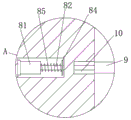
fig. 5 is an enlarged schematic view of a portion a in fig. 2 according to the present invention.
In the figure: 1. fixing a mold; 2. moving the mold; 3. a cavity; 4. a mold core; 5. a flow channel; 6. injection molding a tube; 7. a cavity; 8. a compression assembly; 81. a sleeve; 82. a movable rod; 83. a limiting block; 84. a fixing sheet; 85. a spring; 9. a clamping block; 10. and (4) a groove.
Detailed Description
In order to make the objects, technical solutions and advantages of the embodiments of the present disclosure more clear, the technical solutions of the embodiments of the present disclosure will be described below clearly and completely with reference to the accompanying drawings of the embodiments of the present disclosure.
Unless otherwise defined, technical or scientific terms used herein shall have the ordinary meaning as understood by one of ordinary skill in the art to which this disclosure belongs. The use of the word "comprising" or "comprises", and the like, in this disclosure is intended to mean that the elements or items listed before that word, include the elements or items listed after that word, and their equivalents, without excluding other elements or items. The terms "connected" or "coupled" and the like are not restricted to physical or mechanical connections, but may also include electrical connections, whether direct or indirect. "upper", "lower", "left", "right", and the like are used merely to indicate relative positional relationships, and when the absolute position of the object being described is changed, the relative positional relationships may also be changed accordingly.
Referring to fig. 1-5, an injection mold for producing a refrigerator drawer comprises a fixed mold 1, a movable mold 2 and an injection molding pipe 6, wherein the movable mold 2 is arranged right above the fixed mold 1 and connected through a guide pillar, a cavity 3 is formed in the fixed mold 1, a mold core 4 is fixedly connected to the bottom of the cavity 3, a runner 5 is formed in the middle of the movable mold 2, two ends of the runner 5 are respectively communicated with the upper portion of the movable mold 2 and the cavity 3, symmetrically distributed clamping blocks 9 are arranged in the middle of the runner 5, the bottom end of the injection molding pipe 6 is inserted into the runner 5 and movably connected with the clamping blocks 9, cavities 7 located on two sides of the runner 5 are formed in the movable mold 2, a compression assembly 8 is arranged in each cavity 7, and the compression assembly 8 is in transmission connection.
One end of the sleeve 81 facing the clamping block 9 is provided with a sleeve hole, and one end of the movable rod 82 penetrates through the sleeve hole and is connected with the inner wall of the sleeve hole in a sliding manner.
The limiting block 83 is disc-shaped, the periphery of the limiting block 83 is connected with the inner wall of the sleeve 81 in a sliding mode, and the outer diameter of the limiting block 83 is larger than the inner diameter of the trepan boring.
The inside of movable mould 2 is seted up and is located the recess 10 on the runner 5 lateral wall, and recess 10 and clamp splice 9 are the semi-circular that matches each other, and the middle part of recess 10 and the center of cavity 7 are in same water flat line, and the inner wall sliding connection of clamp splice 9 and recess 10 offers the logical groove that is linked together with cavity 7 on the middle part inner wall of recess 10, and movable rod 82 passes logical groove and mutual sliding connection.
The runner 5 comprises two parts, and the internal diameter of the upper half is greater than the internal diameter of the lower half, and the internal diameter of the lower half is less than the external diameter of the injection molding pipe 6, so that when the injection molding pipe 6 is inserted into the runner 5, only the upper half can be inserted, and the injection molding pipe 6 is prevented from being inserted too deeply.
The utility model discloses when using, insert the runner 5 downwards through the pipe 6 of moulding plastics in, two clamp splices 9 of the bottom downward extrusion of the pipe 6 of moulding plastics, the clamp splice 9 outwards promotes movable rod 82, movable rod 82 drives the inside extrusion spring 85 of stationary blade 84, utilize spring 85 to take place elastic deformation, it receive and releases to realize that movable rod 82 drives the elasticity of clamp splice 9 in runner 5, make the pipe 6 of moulding plastics after extracting, can seal the middle part of runner 5, avoid the dust to get into in the die cavity 3 via runner 5, improve the quality of moulding plastics with this, improve the qualification rate of finished product refrigerator drawer.
The above description is only an exemplary embodiment of the present invention, and is not intended to limit the present invention, the scope of which is defined by the appended claims. Various modifications and equivalents of the invention can be made by those skilled in the art within the spirit and scope of the invention, and such modifications and equivalents should also be considered as falling within the scope of the invention.
Claims (6)
1. An injection mold for producing refrigerator drawers comprises a fixed mold (1), a movable mold (2) and an injection molding pipe (6), and is characterized in that the movable mold (2) is arranged right above the fixed mold (1) and connected through a guide pillar, a cavity (3) is formed in the fixed mold (1), a mold core (4) is fixedly connected to the bottom of the cavity (3), a runner (5) is formed in the middle of the movable mold (2), two ends of the runner (5) are respectively communicated with the upper portion of the movable mold (2) and the cavity (3), symmetrically distributed clamping blocks (9) are arranged in the middle of the runner (5), the bottom end of the injection molding pipe (6) is inserted into the runner (5) and movably connected with the clamping blocks (9), cavities (7) located on two sides of the runner (5) are formed in the movable mold (2), and a compression assembly (8) is arranged in each cavity (7), the compression assembly (8) is in transmission connection with the clamping block (9).
2. The injection mold for producing the drawer of the refrigerator as claimed in claim 1, the compression component (8) comprises a sleeve (81) positioned in the cavity (7), a movable rod (82), a limit block (83), a fixed plate (84) and a spring (85), the sleeve (81) is fixedly arranged on the inner wall of one side of the cavity (7) far away from the flow channel (5), one end of the movable rod (82) is movably sleeved with the sleeve (81), the other end of the movable rod penetrates through the cavity (7) and extends to the outside of the cavity and is fixedly connected with the middle part of the clamping block (9), the limiting block (83) is arranged in the sleeve (81) and is fixedly connected with the movable rod (82), the fixed plate (84) is fixedly sleeved on one side of the middle part of the movable rod (82) which is deviated to the sleeve (81), the spring (85) is movably sleeved on the movable rod (82), and two ends of the spring (85) are respectively fixedly connected with the sleeve (81) and the fixing piece (84).
3. The injection mold for producing the refrigerator drawer as claimed in claim 2, wherein a sleeve hole is formed in one end of the sleeve (81) facing the clamping block (9), and one end of the movable rod (82) penetrates through the sleeve hole and is slidably connected with the inner wall of the sleeve hole.
4. The injection mold for producing the drawer of the refrigerator as claimed in claim 2, wherein the stopper (83) is disc-shaped, the outer circumference of the stopper (83) is slidably connected with the inner wall of the sleeve (81), and the outer diameter of the stopper (83) is larger than the inner diameter of the sleeve hole.
5. The injection mold for producing the refrigerator drawer as claimed in claim 1, wherein a groove (10) located on the side wall of the runner (5) is formed in the movable mold (2), the groove (10) and the clamping block (9) are mutually matched in a semicircular shape, the middle of the groove (10) and the center of the cavity (7) are located on the same horizontal line, and the clamping block (9) is slidably connected with the inner wall of the groove (10).
6. The injection mold for producing the drawer of the refrigerator as claimed in claim 1, wherein the runner (5) is formed by two parts, the upper part has an inner diameter larger than that of the lower part, and the lower part has an inner diameter smaller than the outer diameter of the injection pipe (6).
Priority Applications (1)
| Application Number | Priority Date | Filing Date | Title |
|---|---|---|---|
| CN201922404546.4U CN211492635U (en) | 2019-12-27 | 2019-12-27 | Injection mold is used in production of refrigerator drawer |
Applications Claiming Priority (1)
| Application Number | Priority Date | Filing Date | Title |
|---|---|---|---|
| CN201922404546.4U CN211492635U (en) | 2019-12-27 | 2019-12-27 | Injection mold is used in production of refrigerator drawer |
Publications (1)
| Publication Number | Publication Date |
|---|---|
| CN211492635U true CN211492635U (en) | 2020-09-15 |
Family
ID=72420748
Family Applications (1)
| Application Number | Title | Priority Date | Filing Date |
|---|---|---|---|
| CN201922404546.4U Active CN211492635U (en) | 2019-12-27 | 2019-12-27 | Injection mold is used in production of refrigerator drawer |
Country Status (1)
| Country | Link |
|---|---|
| CN (1) | CN211492635U (en) |
Cited By (1)
| Publication number | Priority date | Publication date | Assignee | Title |
|---|---|---|---|---|
| CN112536989A (en) * | 2020-11-26 | 2021-03-23 | 马红宇 | Automatic injection moulding die mechanism of car steering wheel |
-
2019
- 2019-12-27 CN CN201922404546.4U patent/CN211492635U/en active Active
Cited By (1)
| Publication number | Priority date | Publication date | Assignee | Title |
|---|---|---|---|---|
| CN112536989A (en) * | 2020-11-26 | 2021-03-23 | 马红宇 | Automatic injection moulding die mechanism of car steering wheel |
Similar Documents
| Publication | Publication Date | Title |
|---|---|---|
| CN211492635U (en) | Injection mold is used in production of refrigerator drawer | |
| CN216329849U (en) | Injection mold convenient to drawing of patterns | |
| CN211031020U (en) | Injection mold structure and mold thereof | |
| CN108859033A (en) | A kind of washing machine accessory Injection Mold | |
| CN211031106U (en) | Combined filler injection molding mold | |
| CN210910985U (en) | Yarn nozzle mould | |
| CN208896410U (en) | Miniature ox horn stalking plastic structure | |
| CN218462832U (en) | Fan blade mould | |
| CN111823525A (en) | High-quality injection mold with heating function | |
| CN215750402U (en) | Mold structure for producing injection molding combining piece | |
| CN209738188U (en) | Cylinder type air conditioner rear shell forming die | |
| CN217704452U (en) | Assembled children wardrobe panel shape structure forming die that preapres for an unfavorable turn of events | |
| CN217802986U (en) | Injection mold with three-jaw integrated internal pulling structure | |
| CN218576882U (en) | Fruit and vegetable box decorative plate mold | |
| CN220373775U (en) | Injection mold for molding in-mold inserts | |
| CN211683257U (en) | High-precision injection mold | |
| CN220373790U (en) | Injection mold of automobile door handle main body | |
| CN216968541U (en) | Small-size long needle tubulose mould structure | |
| CN216267364U (en) | Prevent horizontal displacement's pivot subassembly injection mold | |
| CN211640783U (en) | Precise injection mold | |
| CN208514904U (en) | It is a kind of to prevent molten material adhesion injection mold for dust catcher production | |
| CN217226478U (en) | Spectacle frame forming injection mold | |
| CN216760618U (en) | Improve plastic part seam segment difference's injection mold | |
| CN215512053U (en) | High-precision die assembly anti-deviation automobile front bumper die | |
| CN211221842U (en) | Injection molding mold for special-shaped flexible glue pipe fitting |
Legal Events
| Date | Code | Title | Description |
|---|---|---|---|
| GR01 | Patent grant | ||
| GR01 | Patent grant |