CN211464918U - Flange processing frock in valve body - Google Patents
Flange processing frock in valve body Download PDFInfo
- Publication number
- CN211464918U CN211464918U CN201922259260.1U CN201922259260U CN211464918U CN 211464918 U CN211464918 U CN 211464918U CN 201922259260 U CN201922259260 U CN 201922259260U CN 211464918 U CN211464918 U CN 211464918U
- Authority
- CN
- China
- Prior art keywords
- flange
- plate
- valve body
- positioning
- bent plate
- Prior art date
- Legal status (The legal status is an assumption and is not a legal conclusion. Google has not performed a legal analysis and makes no representation as to the accuracy of the status listed.)
- Active
Links
Images


Abstract
The utility model discloses a flange processing frock in valve body belongs to valve tooling equipment technical field, including the flat mould that is used for connecting the numerical control lathe main shaft, one side fixedly connected with bent plate of flat mould, coaxial backing plate and the clamp plate of being equipped with in proper order on the bent plate, it fixes to wait to process the flange spare the backing plate with between the clamp plate, follow the backing plate with the axis of clamp plate runs through there is the dabber, the upper end of dabber is fixed with first upper nut, the dabber stretches out the lower extreme of bent plate is fixed with first lower nut, on the bent plate for the opposite side of flat mould is equipped with flange front end fixed establishment. The utility model discloses guaranteed the axiality of processing effectively, solved the problem that the axiality is hardly guaranteed to flange processing frock in the current valve body.
Description
Technical Field
The utility model relates to a valve tooling equipment technical field, in particular to flange processing frock in valve body.
Background
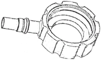
At present, a tool for installing and fixing a workpiece to be machined on a lathe is usually fixedly arranged on a working platform of the lathe. In the process of mounting a workpiece on a tool, firstly, the position of the workpiece needs to be adjusted, namely, the position is aligned on a machine tool; and then clamping and fixing the workpiece through a tool. The middle flange of the valve body is shown in figure 1, the machining part of the middle flange is provided with a plurality of internal threads and deep holes, and a vibrating cutter, a deep hole drill deviation, an out-of-coaxiality and the like are easily generated during machining; and moreover, the machining coaxiality is difficult to ensure due to the fact that multiple machining parts such as an outer circle and an external thread exist.
In addition, the flange needs to be aligned on a machine tool in the process of turning and mounting every time, and the machine tool cannot be used in the part of time, so that the use efficiency and the production efficiency of the machine tool are greatly reduced.
SUMMERY OF THE UTILITY MODEL
Technical problem to be solved
The utility model provides a flange processing frock in valve body solves the problem that the coaxiality is hardly guaranteed to flange processing frock in the current valve body.
(II) technical scheme
In order to solve the technical problem, the utility model provides a technical scheme does:
the utility model provides a flange processing frock in valve body, is including the flat mould that is used for connecting the numerical control lathe main shaft, one side fixedly connected with bent plate of flat mould, coaxial backing plate and the clamp plate of being equipped with in proper order on the bent plate, wait to process the flange spare and fix the backing plate with between the clamp plate, follow the backing plate with the axis of clamp plate runs through there is the dabber, the upper end of dabber is fixed with first upper nut, the dabber stretches out the lower extreme of bent plate is fixed with first lower nut, for on the bent plate the opposite side of flat mould is equipped with flange front end fixed establishment.
Preferably, the flange front end fixing mechanism comprises a positioning column and a positioning block, the positioning column is fixed on the bent plate, the positioning block is fixed above the positioning column, two positioning bolts are symmetrically arranged on two sides of the positioning column and are in threaded connection with the bent plate, lower pressing plates penetrate through the upper portions of the two positioning bolts, and the front end of the flange piece to be machined is fixed between the positioning block and the lower pressing plates.
Preferably, the upper surface of the positioning block is provided with an arc-shaped positioning groove.
Preferably, a second upper nut is fixed on a part of the positioning bolt, which penetrates out of the lower pressure plate; and a second lower nut is arranged at the lower part of the positioning bolt and is positioned on the upper surface of the bent plate.
Preferably, a supporting plate is arranged at one end, close to the flat die, below the bent plate, and the supporting plate is fixedly connected with the flat die through bolts.
Wherein, preferably, the top of flat mould is equipped with counter weight iron plate.
(III) advantageous effects
The technical scheme provided by the utility model, compared with prior art, following beneficial effect has:
the utility model discloses a flange processing frock is right angle anchor clamps assembly in the valve body, connects the numerical control lathe main shaft through the flat mould, places on anchor clamps for the location benchmark with product right-hand member face and hole, and the upper end compresses tightly with the clamp plate, and the front end adopts flange front end fixed establishment excircle location, and flange center to numerical control lathe centre of rotation in the adjustment bores the hole size such as deep hole, processing deep hole, has guaranteed the axiality of processing effectively, solves the problem that the axiality is hardly guaranteed to flange processing frock in the current valve body.
Drawings
In order to more clearly illustrate the embodiments of the present invention or the technical solutions in the prior art, the drawings needed to be used in the description of the embodiments or the prior art will be briefly described below, it is obvious that the drawings in the following description are only some embodiments of the present invention, and for those skilled in the art, other embodiments can be obtained according to the drawings without creative efforts;
fig. 1 is a schematic structural view of a middle flange to be processed in the present invention;
fig. 2 is a schematic structural view of the middle flange turning tool of the present invention;
FIG. 3 is a schematic view of the flat die configuration of FIG. 2 taken along direction A;
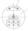
fig. 4 is a schematic structural view of the flange front end fixing mechanism in the direction B in fig. 2.
In the figure: 1. the steel plate forming machine comprises a flat die, 2 parts of a bent plate, 3 parts of a base plate, 4 parts of a pressing plate, 5 parts of a mandrel, 6 parts of a first upper nut, 7 parts of a first lower nut, 8 parts of a positioning column, 9 parts of a positioning block, 10 parts of a positioning bolt, 11 parts of a lower pressing plate, 12 parts of a second upper nut, 13 parts of a second lower nut, 14 parts of a supporting plate, 15 parts of a balance weight iron block, 16 parts of a spring gasket
Detailed Description
The technical solution of the present invention will be described clearly and completely below with reference to specific embodiments of the present invention, and it should be understood that the described embodiments are only some embodiments of the present invention, not all embodiments. Based on the embodiments in the present invention, all other embodiments obtained by a person skilled in the art without creative work belong to the protection scope of the present invention.
As shown in fig. 2 to 4, the embodiment provides a tool for machining a flange in a valve body, wherein a schematic structural diagram of the flange to be machined is shown in fig. 1.
The flange processing tool in the valve body comprises a flat die 1 used for being connected with a main shaft of a numerical control lathe, a bent plate 2 is fixedly connected to one side of the flat die 1, the bent plate 2 and the flat die 1 are integrally formed, and in the embodiment, the bent plate 2 and the flat die can also be fixedly connected through other conventional connection modes such as welding, threaded connection and the like.
The upper shaft of bent plate 2 is equipped with backing plate 3 and clamp plate 4 in proper order, treats that processing flange spare is fixed between backing plate 3 and clamp plate 4, and it has dabber 5 to run through along the axis of backing plate 3 and clamp plate 4, and the upper end of dabber 5 is fixed with first upper nut 6, and the lower extreme that the bent plate 2 was stretched out to dabber 5 is fixed with first lower nut 7, is equipped with spring shim 16 between first lower nut 7 and the bent plate 2. And a flange front end fixing mechanism is arranged on the other side of the bent plate 2 relative to the flat die 1. The flange front end fixing mechanism is used for fixing the front end of a flange piece to be processed.
Wherein, flange front end fixed establishment includes reference column 8 and locating piece 9, and reference column 8 is fixed on bent plate 2, and locating piece 9 is fixed in reference column 8 top, and 8 bilateral symmetry of reference column are equipped with two positioning bolt 10, and positioning bolt 10 and bent plate 2 threaded connection, two positioning bolt 10 upper portions have worn holding down plate 11, wait to process flange spare front end and fix between locating piece 9 and holding down plate 11.
In order to accurately position the front end of the flange piece to be processed, the upper surface of the positioning block 9 is provided with an arc-shaped positioning groove.
Wherein, a second upper nut 12 is fixed on the part of the positioning bolt 10 penetrating out of the lower pressure plate 11; the lower part of the positioning bolt 10 is provided with a second lower nut 13, and the second lower nut 13 is positioned on the upper surface of the bent plate 2.
Wherein, the one end that is close to flat mould 1 under bent plate 2 is equipped with backup pad 14, and backup pad 14 passes through bolt fixed connection with flat mould 1.
Wherein, the top of flat die 1 is equipped with counter weight iron plate 15, and counter weight iron plate 15 has improved the stationarity of processing through hexagon socket head cap screw and flat die 1 fixed connection, counter weight iron plate 15.
The working process is as follows:
1. firstly, positioning and processing inner holes and sizes of right end parts of the flange part to be processed by the inner holes and the left end surface of the flange part to be processed.
2. The right end face and the inner hole of the flange part to be machined are used as positioning references, the flange part is placed on a clamp and is tightly pressed by a pressing plate 4, the center of the end face is tightly pressed by a tip, and all relevant sizes are guaranteed by all sizes outside the flange during machining.
3. The right-angle clamp assembly is connected with a main shaft of the numerical control lathe through a flat die 1, the right end face and an inner hole of a product are used as positioning references, the right-angle clamp assembly is placed on a clamp, the upper end of the right-angle clamp assembly is pressed by a pressing plate 4, the front end of the right-angle clamp assembly is positioned by adopting a floating adjustable supporting block in an excircle mode, the center of a middle flange is adjusted to the rotation center of the numerical control lathe, deep.
It should be noted that, in this document, terms such as "comprises," "comprising," or any other variation thereof, are intended to cover a non-exclusive inclusion, such that a process, method, article, or apparatus that comprises a list of elements does not include only those elements but may include other elements not expressly listed or inherent to such process, method, article, or apparatus. Without further limitation, an element defined by the phrase "comprising an … …" does not exclude the presence of other identical elements in a process, method, article, or apparatus that comprises the element.
Although embodiments of the present invention have been shown and described, it will be appreciated by those skilled in the art that changes, modifications, substitutions and alterations can be made in these embodiments without departing from the principles and spirit of the invention, the scope of which is defined in the appended claims and their equivalents.
Claims (6)
1. The utility model provides a flange processing frock in valve body which characterized in that: including the flat die that is used for connecting the numerical control lathe main shaft, one side fixedly connected with bent plate of flat die, coaxial backing plate and the clamp plate of being equipped with in proper order on the bent plate, wait to process the flange spare and fix the backing plate with between the clamp plate, follow the backing plate with the axis of clamp plate runs through there is the dabber, the upper end of dabber is fixed with first upper nut, the dabber stretches out the lower extreme of bent plate is fixed with first lower nut, for on the bent plate the opposite side of flat die is equipped with flange front end fixed establishment.
2. The tool for machining the flange in the valve body according to claim 1, wherein the tool comprises: the flange front end fixing mechanism comprises a positioning column and a positioning block, the positioning column is fixed on the bent plate, the positioning block is fixed above the positioning column, two positioning bolts are symmetrically arranged on two sides of the positioning column and are in threaded connection with the bent plate, lower pressing plates penetrate through the upper portions of the two positioning bolts, and the front end of a flange piece to be machined is fixed between the positioning block and the lower pressing plates.
3. The tool for machining the flange in the valve body according to claim 2, wherein the tool comprises: and the upper surface of the positioning block is provided with an arc-shaped positioning groove.
4. The tool for machining the flange in the valve body according to claim 2, wherein the tool comprises: a second upper nut is fixed on the part of the positioning bolt penetrating out of the lower pressure plate; and a second lower nut is arranged at the lower part of the positioning bolt and is positioned on the upper surface of the bent plate.
5. The tool for machining the flange in the valve body according to claim 1, wherein the tool comprises: and a supporting plate is arranged at one end of the bent plate, which is close to the flat die, and the supporting plate is fixedly connected with the flat die through a bolt.
6. The tool for machining the flange in the valve body according to claim 1, wherein the tool comprises: and a counterweight iron block is arranged at the top of the flat die.
Priority Applications (1)
| Application Number | Priority Date | Filing Date | Title |
|---|---|---|---|
| CN201922259260.1U CN211464918U (en) | 2019-12-16 | 2019-12-16 | Flange processing frock in valve body |
Applications Claiming Priority (1)
| Application Number | Priority Date | Filing Date | Title |
|---|---|---|---|
| CN201922259260.1U CN211464918U (en) | 2019-12-16 | 2019-12-16 | Flange processing frock in valve body |
Publications (1)
| Publication Number | Publication Date |
|---|---|
| CN211464918U true CN211464918U (en) | 2020-09-11 |
Family
ID=72367407
Family Applications (1)
| Application Number | Title | Priority Date | Filing Date |
|---|---|---|---|
| CN201922259260.1U Active CN211464918U (en) | 2019-12-16 | 2019-12-16 | Flange processing frock in valve body |
Country Status (1)
| Country | Link |
|---|---|
| CN (1) | CN211464918U (en) |
-
2019
- 2019-12-16 CN CN201922259260.1U patent/CN211464918U/en active Active
Similar Documents
| Publication | Publication Date | Title |
|---|---|---|
| CN202780513U (en) | Fixture for round bar sawing and cutting | |
| CN201493701U (en) | Locomotive axle suspension case clamp | |
| CN202701457U (en) | Disc-type component drilling tool | |
| CN211464918U (en) | Flange processing frock in valve body | |
| CN206795344U (en) | A kind of turning attachment for being used to process square cross | |
| CN209886730U (en) | Drilling and positioning tool for connecting discs of mechanical arms | |
| CN204748067U (en) | A anchor clamps for four -axis machine tool | |
| CN208132474U (en) | CNC milling machine frock clamp | |
| CN103128579A (en) | Oil pump machining center milling drilling clamping device | |
| CN211465611U (en) | Well flange car frock | |
| CN210306791U (en) | Axle type part quick clamping frock of axle head milling flutes | |
| CN210010730U (en) | Copper part circular arc welt processing frock | |
| CN206382664U (en) | A kind of tool for being used to process circular big cavity plate | |
| CN211589288U (en) | Machining clamp for milling, drilling and reaming of brake arm | |
| CN213163518U (en) | Quick positioning jig for circular workpiece for linear cutting | |
| CN203125156U (en) | Cylindrical part rapid clamping and locating fixture | |
| CN211387717U (en) | Work fixture | |
| CN214816629U (en) | CNC revolving cylinder presses material tool | |
| CN104842028A (en) | Electrode guiding device of electric discharge machine | |
| CN217914187U (en) | Beveling machine center aligning device | |
| CN216681240U (en) | Cutting auxiliary tool | |
| CN204565367U (en) | A kind of electric discharge machine electrode guide | |
| CN217648225U (en) | Three-point positioning tool | |
| CN214868336U (en) | Radiator box welding frock | |
| CN215880779U (en) | Machining clamp for rotary part of aero-engine |
Legal Events
| Date | Code | Title | Description |
|---|---|---|---|
| GR01 | Patent grant | ||
| GR01 | Patent grant | ||
| CP01 | Change in the name or title of a patent holder | ||
| CP01 | Change in the name or title of a patent holder |
Address after: No.96 Zizhu Road, Zhengzhou hi tech Industrial Development Zone, Henan Province Patentee after: Henan Fujia fluid control technology Co., Ltd Address before: No.96 Zizhu Road, Zhengzhou hi tech Industrial Development Zone, Henan Province Patentee before: Henan taoen Machinery Co.,Ltd. |