CN211438312U - Trimming device for inner layer of motorcycle fuel tank - Google Patents
Trimming device for inner layer of motorcycle fuel tank Download PDFInfo
- Publication number
- CN211438312U CN211438312U CN201922241374.3U CN201922241374U CN211438312U CN 211438312 U CN211438312 U CN 211438312U CN 201922241374 U CN201922241374 U CN 201922241374U CN 211438312 U CN211438312 U CN 211438312U
- Authority
- CN
- China
- Prior art keywords
- fixedly connected
- fixed frame
- trimming device
- motor
- fly leaf
- Prior art date
- Legal status (The legal status is an assumption and is not a legal conclusion. Google has not performed a legal analysis and makes no representation as to the accuracy of the status listed.)
- Active
Links
Images


Landscapes
- Working Measures On Existing Buildindgs (AREA)
Abstract
The utility model discloses a trimming device of motorcycle oil tank inlayer includes: a base; the bottom ends of the two rotating rods are respectively and rotatably connected to two sides of the top of the base, the outer surfaces of the two rotating rods are respectively and fixedly connected with a first bevel gear, the inner surfaces of the two rotating rods are respectively in threaded connection with a threaded rod, and a top plate is respectively and fixedly connected between the top ends of the two threaded rods; a fixing frame; the bottom of fixed frame is fixed in the top of roof, the utility model relates to a trimming device technical field. This trimming device of motorcycle oil tank inlayer places on one another through first break bar and second break bar, and synchronous rotation, the place that the cutting edge offseted forms the incision, can cut the oil tank inlayer of two looks superpositions simultaneously to the device is effectual makes the disintegrating slag after the cutting can be collected, prevents to scatter to increase clean dynamics on ground, and the effectual regulation that makes the device can carry out the height makes things convenient for the people of different heights to use.
Description
Technical Field
The utility model relates to a cutting edge device technical field specifically is a cutting edge device of motorcycle oil tank inlayer.
Background
When the oil tank is manufactured, the oil tank consists of two layers, namely an outer layer and an inner layer, the inner layer is manufactured by a die, and after the inner layer is punched and formed by the die, edges need to be cut off to fit the boundary of the outer layer.
The trimming device of current motorcycle oil tank inlayer is tailor by a drift, and the blanking of the continuous shaping of formula of punching a hole can only be tailor one once, and the trimming in addition becomes the zigzag, and is not pleasing to the eye, will cause the condition of an inefficiency like this, can not adjust according to user's height moreover to the disintegrating slag of tailorring off also can't be fine collection, lead to using comparatively inconvenient.
SUMMERY OF THE UTILITY MODEL
The utility model provides a to prior art not enough, the utility model provides a trimming device of motorcycle oil tank inlayer has solved and has used inconvenient problem.
In order to achieve the above purpose, the utility model discloses a following technical scheme realizes: an edge cutting device for an inner layer of a motorcycle fuel tank comprises:
a base;
the bottom ends of the two rotating rods are respectively and rotatably connected to two sides of the top of the base, the outer surfaces of the two rotating rods are respectively and fixedly connected with a first bevel gear, the inner surfaces of the two rotating rods are respectively in threaded connection with a threaded rod, and a top plate is respectively and fixedly connected between the top ends of the two threaded rods;
a fixing frame; the bottom of the fixed frame is fixed to the top of the top plate, the bottom of the inner wall of the fixed frame is fixedly connected with a first motor, the first motor is connected with an external power supply through a control switch, the bottom of the inner wall of the fixed frame is fixedly connected with a speed reducer on the left side of the first motor, a shaft coupling is arranged between an output shaft of the speed reducer and an output shaft of the first motor, another output shaft of the speed reducer is fixedly connected with a first rotating shaft, a first belt pulley is fixedly connected to the outer surface of the first rotating shaft, one end of the first rotating shaft penetrates through the fixed frame and extends to the outside of the fixed frame, and a first cutter wheel is arranged on the outer surface of one end of the first rotating shaft extending;
the second pivot, the second pivot rotate connect in one side of fixed frame inner wall, the fixed surface of second pivot is connected in the second belt pulley, and the transmission is connected with the belt between the surface of second belt pulley and first belt pulley, the one end of second pivot runs through fixed frame extends to the outside of fixed frame, the second pivot extends to the surface of the outside one end of fixed frame is provided with the second break bar.
Further, the both sides at base top just are located two the equal fixedly connected with backup pad in the relative one side of dwang, two rotate between the relative one side of backup pad and be connected with the rotation axis, the first gear of surface fixedly connected with of rotation axis, the top of base just is located two one side fixedly connected with second motor that the backup pad is relative, the second motor passes through control switch and is connected with external power, and the second motor is servo motor, can just reverse, the output shaft fixedly connected with second gear of second motor, the surface of second gear and the surface engagement of first gear.
Furthermore, two ends of the rotating shaft respectively penetrate through the two supporting plates and extend to the side, away from the two supporting plates, two ends of the rotating shaft are fixedly connected with second bevel gears, and the outer surfaces of the two second bevel gears are meshed with the outer surfaces of the two first bevel gears.
Furthermore, an open slot is formed in the top of the top plate, and guide plates are fixedly connected to the two sides of the top plate.
Furthermore, the bottom of the top plate is fixedly connected with a collecting box, the top of the collecting box is provided with an opening matched with the opening groove, the two sides of the inner wall of the collecting box are fixedly connected with hydraulic cylinders, and one side of each of the two hydraulic cylinders opposite to each other is fixedly connected with a pressing plate.
Furthermore, the front of the collecting box is provided with a door plate, the front of the door plate is fixedly connected with a fixing block, a through hole is formed in one side of the fixing block, and the front of the collecting box is located on the right side of the door plate and is fixedly connected with a U-shaped groove.
Further, swing joint has the fly leaf between the top of U type inslot wall and the bottom, the draw-in groove has been seted up in the left side of fly leaf, draw-in groove and fixed block looks adaptation, the recess has been seted up to the inside of fly leaf, sliding connection has the sliding block between the top of recess inner wall and the bottom, the left side fixedly connected with stopper of sliding block, the left side of stopper is run through the fly leaf extends to the outside of fly leaf, the top fixedly connected with of sliding block draws the piece, the top that draws the piece runs through the fly leaf extends to the top of fly leaf, the right side of sliding block with be provided with expanding spring between the inside right side of recess.
Compared with the prior art, the beneficial effects of the utility model are that:
(1) this trimming device on motorcycle oil tank inlayer, through the start-up of first motor, first motor drives first pivot through the reduction gear after slowing down and rotates, and first pivot drives the second pivot rotation, and then makes first break bar and second break bar rotate, and these two break bars are placed one on the other, rotate in step, and the place that the cutting edge offseted forms the incision, can cut the oil tank inlayer of two looks superpositions simultaneously.
(2) This trimming device of motorcycle oil tank inlayer, make the disintegrating slag after the cutting drop in the collecting box through deflector and open slot, start through two pneumatic cylinders, two pneumatic cylinders drive two clamp plate relative motion, compress tightly the disintegrating slag, make the collecting box can increase and collect the space, it is full when the collecting box collects gradually, draw the piece and then make the through-hole that the stopper withdrawed from the fixed block through manual slip, the upset fly leaf makes the door plant not have the restriction, open the door plant and clear up the collecting box is inside, effectual disintegrating slag after making the cutting can be collected, prevent to scatter and increase clean dynamics ground.
This trimming device on motorcycle oil tank inlayer, through the start-up of second motor, the second motor rotates and drives the rotation axis rotation, and the rotation axis drives second conical gear and first conical gear and drives two dwangs rotatoryly, and then makes two threaded rods upward movement gradually, and then makes roof upward movement gradually, and effectual messenger's device can carry out the regulation of height, makes things convenient for the people of different heights to use.
Drawings
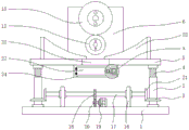
Fig. 1 is a schematic structural view of the present invention;
figure 2 is a side view of the fixing frame shown in figure 1;
FIG. 3 is a top view of the collection bin shown in FIG. 1;
FIG. 4 is an enlarged view of a portion of FIG. 1 at A;
fig. 5 is a bottom view of the movable plate shown in fig. 4.
In the figure: 1-base, 2-rotating rod, 3-first conical gear, 4-threaded rod, 5-top plate, 6-fixing frame, 7-fixing first motor, 8-reducer, 9-coupler, 10-first rotating shaft, 11-first belt pulley, 12-first knife flywheel, 13-second rotating shaft, 14-second belt pulley, 15-second knife flywheel, 16-supporting plate, 17-rotating shaft, 18-first gear, 19-second motor, 20-second gear, 21-second conical gear, 22-open slot, 23-guide plate, 24-collecting box, 25-hydraulic cylinder, 26-pressing plate, 27-door plate, 28-fixing block, 29-U-shaped slot, 30-movable plate, 31-clamping slot, 32-groove, 33-sliding block, 34-limiting block, 35-pulling block and 36-expansion spring.
Detailed Description
The technical solutions in the embodiments of the present invention will be described clearly and completely with reference to the accompanying drawings in the embodiments of the present invention, and it is obvious that the described embodiments are only some embodiments of the present invention, not all embodiments. Based on the embodiments in the present invention, all other embodiments obtained by a person skilled in the art without creative work belong to the protection scope of the present invention.
Referring to fig. 1-5, the present invention provides a technical solution: an edge cutting device for an inner layer of a motorcycle fuel tank comprises:
a base 1;
the bottom ends of the two rotating rods 2 are respectively and rotatably connected to two sides of the top of the base 1, the outer surfaces of the two rotating rods 2 are respectively and fixedly connected with a first bevel gear 3, the inner surfaces of the two rotating rods 2 are respectively and threadedly connected with a threaded rod 4, and a top plate 5 is respectively and fixedly connected between the top ends of the two threaded rods 4;
a fixed frame 6; the bottom of the fixed frame 6 is fixed to the top of the top plate 5, the bottom of the inner wall of the fixed frame 6 is fixedly connected with a first motor 7, the bottom of the inner wall of the fixed frame 6 is fixedly connected with a speed reducer 8 positioned on the left side of the first motor 7, a coupling 9 is arranged between an output shaft of the speed reducer 8 and an output shaft of the first motor 7, the other output shaft of the speed reducer 8 is fixedly connected with a first rotating shaft 10, the outer surface of the first rotating shaft 10 is fixedly connected with a first belt pulley 11, one end of the first rotating shaft 10 penetrates through the fixed frame 6 and extends to the outside of the fixed frame 6, and the outer surface of one end of the first rotating shaft 10 extending to the outside of the fixed frame 6 is provided with;
The oil tank is started through the first motor 7, the first motor 7 drives the first rotating shaft 10 to rotate after being decelerated through the speed reducer 8, the first rotating shaft 10 drives the first cutter wheel 12 to rotate, the first rotating shaft 10 drives the second rotating shaft 13 to rotate through the first belt pulley 11 and the second belt pulley 14, the second rotating shaft 13 drives the second cutter wheel 15 to rotate, the first cutter wheel 12 and the second cutter wheel 15 rotate synchronously to cut the inner layer of the oil tank, the first cutter wheel 12 and the second cutter wheel 15 are connected in a bolt-type detachable mode, and the two cutter wheels are convenient to replace after being abraded.
The both sides at base 1 top just are located two the equal fixedly connected with backup pad 16 in one side that dwang 2 is relative, two rotate between the relative one side of backup pad 16 and be connected with rotation axis 17, the first gear 18 of outer fixed surface of rotation axis 17 is connected with, the top of base 1 just is located two the relative one side fixedly connected with second motor 19 of backup pad 16, the output shaft fixedly connected with second gear 20 of second motor 19 rotates through second motor 19 and drives second gear 20 rotatory, and second gear 20 drives first gear 18 rotatory, and then makes second motor 19 drive rotation axis 17 rotatory.
Two backup pads 16 are run through respectively and extend to the one side that two backup pads 16 separated from each other at the both ends of rotation axis 17, the equal fixedly connected with second bevel gear 21 in both ends of rotation axis 17, second motor 19 drives rotation axis 27 rotatory, and then make two second bevel gears 21 rotatory, two second bevel gear 21 drive two first bevel gear 3 rotations, and then make dwang 2 rotatory, dwang 2 is rotatory to be made threaded rod 4 drive roof 5 upward movement, and the same is said, 19 antiport of second motor can drive roof 5 downstream, thereby make whole device can realize that the regulation person of facilitating the use of height uses.
The bottom fixedly connected with collecting box 24 of roof 5, the equal fixedly connected with pneumatic cylinder 25 in both sides of collecting box 24 inner wall, two the equal fixedly connected with clamp plate 26 in one side that pneumatic cylinder 25 is relative drives two clamp plate 26 relative motion through two pneumatic cylinders 25, and then carries out the compaction to the disintegrating slag for collecting box 24 can collect more disintegrating slag.
The front surface of the collecting box 24 is provided with a door plate 27, the front surface of the door plate 27 is fixedly connected with a fixing block 28, and the front surface of the collecting box 24 and the right side of the door plate 27 are fixedly connected with a U-shaped groove 29.
A movable plate 30 is movably connected between the top and the bottom of the inner wall of the U-shaped groove 29, a clamping groove 31 is formed on the left side of the movable plate 30, a groove 32 is arranged in the movable plate 30, a sliding block 33 is connected between the top and the bottom of the inner wall of the groove 32 in a sliding manner, a limit block 34 is fixedly connected to the left side of the sliding block 33, the left side of the limit block 34 penetrates through the movable plate 30 and extends to the outside of the movable plate 30, the top of the sliding block 33 is fixedly connected with a pulling block 35, the top of the pulling block 35 penetrates through the movable plate 30 and extends to the top of the movable plate 30, a telescopic spring 36 is arranged between the right side of the sliding block 33 and the right side inside the groove 32, the left slot 31 of the movable plate 30 is clamped on two sides of the fixed block 28, the sliding spring 36 extrudes the sliding block 33, and the sliding block 33 drives the limit block 34 to be inserted into the through hole on the fixed block 28, so that the door panel 27 is fixed.
When the oil tank shearing machine works, the first motor 7 is started, the first motor 7 drives the first rotating shaft 10 to rotate after being decelerated by the speed reducer 8, the first rotating shaft 10 drives the second rotating shaft 13 to rotate, and further the first cutter wheel 12 and the second cutter wheel 15 rotate, the two cutter wheels are placed one above the other and rotate synchronously, and a shearing edge is formed at the position where the cutting edges abut against each other, so that the inner layers of two overlapped oil tanks can be sheared simultaneously;
the cut crushed slag falls into the collection box 24 through the guide plate 23 and the open slot 22, the two hydraulic cylinders 25 drive the two pressing plates 26 to move relatively to compress the crushed slag through the starting of the two hydraulic cylinders 25, so that the collection box 24 can enlarge the collection space, when the collection box 24 is gradually fully collected, the limiting block 34 is withdrawn from the through hole of the fixed block 28 through the manual sliding pull block 35, the movable plate 30 is overturned to enable the door plate 27 not to be limited, and the door plate 27 is opened to clean the inside of the collection box 24;
through the start-up of second motor 19, second motor 19 rotates and drives rotation axis 17 and rotate, and rotation axis 17 drives second conical gear 21 and first conical gear 3 and drives two dwang 2 rotatorys, and then makes two threaded rod 4 upward movement gradually, and then makes roof 5 upward movement gradually.
It is noted that, herein, relational terms such as first and second, and the like may be used solely to distinguish one entity or action from another entity or action without necessarily requiring or implying any actual such relationship or order between such entities or actions. Also, the terms "comprises," "comprising," or any other variation thereof, are intended to cover a non-exclusive inclusion, such that a process, method, article, or apparatus that comprises a list of elements does not include only those elements but may include other elements not expressly listed or inherent to such process, method, article, or apparatus.
The above description is only a preferred embodiment of the present invention, and should not be taken as limiting the invention, and any modifications, equivalent replacements, improvements, etc. made within the spirit and principle of the present invention should be included in the protection scope of the present invention.
Claims (7)
1. The utility model provides a trimming device of motorcycle oil tank inlayer which characterized in that: the method comprises the following steps:
a base;
the bottom ends of the two rotating rods are respectively and rotatably connected to two sides of the top of the base, the outer surfaces of the two rotating rods are respectively and fixedly connected with a first bevel gear, the inner surfaces of the two rotating rods are respectively in threaded connection with a threaded rod, and a top plate is respectively and fixedly connected between the top ends of the two threaded rods;
a fixing frame; the bottom of the fixed frame is fixed to the top of the top plate, the bottom of the inner wall of the fixed frame is fixedly connected with a first motor, the bottom of the inner wall of the fixed frame is fixedly connected with a speed reducer on the left side of the first motor, a shaft coupling is arranged between an output shaft of the speed reducer and an output shaft of the first motor, the other output shaft of the speed reducer is fixedly connected with a first rotating shaft, the outer surface of the first rotating shaft is fixedly connected with a first belt pulley, one end of the first rotating shaft penetrates through the fixed frame and extends to the outside of the fixed frame, and the outer surface of one end of the first rotating shaft, which extends to the outside of the fixed frame;
the second pivot, the second pivot rotate connect in one side of fixed frame inner wall, the surface fixed connection of second pivot is in the second belt pulley, the one end of second pivot runs through fixed frame extends to the outside of fixed frame, the second pivot extends to the surface of the outside one end of fixed frame is provided with the second break bar.
2. A trimming device for an inner layer of a motorcycle fuel tank according to claim 1, wherein: the both sides at base top just are located two the equal fixedly connected with backup pad in the relative one side of dwang, two rotate between the relative one side of backup pad and be connected with the rotation axis, the first gear of surface fixedly connected with of rotation axis, the top of base just is located two one side fixedly connected with second motor that the backup pad is relative, the output shaft fixedly connected with second gear of second motor.
3. A trimming device for an inner layer of a motorcycle fuel tank according to claim 2, wherein: the both ends of rotation axis run through two backup pads respectively and extend to the one side that two backup pads are kept apart from, the both ends of rotation axis all fixedly connected with second bevel gear.
4. A trimming device for an inner layer of a motorcycle fuel tank according to claim 1, wherein: the top of roof has seted up the open slot, the equal fixedly connected with deflector in both sides at roof top.
5. A trimming device for an inner layer of a motorcycle fuel tank according to claim 1, wherein: the bottom fixedly connected with collecting box of roof, the equal fixedly connected with pneumatic cylinder in both sides of collecting box inner wall, two the equal fixedly connected with clamp plate in the relative one side of pneumatic cylinder.
6. An edge trimming device for an inner layer of a motorcycle fuel tank according to claim 5, wherein: the front of the collecting box is provided with a door plate, the front of the door plate is fixedly connected with a fixing block, and the front of the collecting box is positioned on the right side of the door plate and is fixedly connected with a U-shaped groove.
7. An edge trimming device for an inner layer of a motorcycle fuel tank as claimed in claim 6, wherein: swing joint has the fly leaf between the top of U type inslot wall and the bottom, the draw-in groove has been seted up in the left side of fly leaf, the inside recess of fly leaf, sliding connection has the sliding block between the top of recess inner wall and the bottom, the left side fixedly connected with stopper of sliding block, the left side of stopper is run through the fly leaf extends to the outside of fly leaf, the top fixedly connected with of sliding block draws the piece, the top that draws the piece is run through the fly leaf extends to the top of fly leaf, the right side of sliding block with be provided with expanding spring between the inside right side of recess.
Priority Applications (1)
| Application Number | Priority Date | Filing Date | Title |
|---|---|---|---|
| CN201922241374.3U CN211438312U (en) | 2019-12-15 | 2019-12-15 | Trimming device for inner layer of motorcycle fuel tank |
Applications Claiming Priority (1)
| Application Number | Priority Date | Filing Date | Title |
|---|---|---|---|
| CN201922241374.3U CN211438312U (en) | 2019-12-15 | 2019-12-15 | Trimming device for inner layer of motorcycle fuel tank |
Publications (1)
| Publication Number | Publication Date |
|---|---|
| CN211438312U true CN211438312U (en) | 2020-09-08 |
Family
ID=72312663
Family Applications (1)
| Application Number | Title | Priority Date | Filing Date |
|---|---|---|---|
| CN201922241374.3U Active CN211438312U (en) | 2019-12-15 | 2019-12-15 | Trimming device for inner layer of motorcycle fuel tank |
Country Status (1)
| Country | Link |
|---|---|
| CN (1) | CN211438312U (en) |
Cited By (1)
| Publication number | Priority date | Publication date | Assignee | Title |
|---|---|---|---|---|
| CN112518368A (en) * | 2020-11-27 | 2021-03-19 | 湖南昌泰金属设备制造有限公司 | Fixing device for cutting metal pipe of hardware product |
-
2019
- 2019-12-15 CN CN201922241374.3U patent/CN211438312U/en active Active
Cited By (1)
| Publication number | Priority date | Publication date | Assignee | Title |
|---|---|---|---|---|
| CN112518368A (en) * | 2020-11-27 | 2021-03-19 | 湖南昌泰金属设备制造有限公司 | Fixing device for cutting metal pipe of hardware product |
Similar Documents
| Publication | Publication Date | Title |
|---|---|---|
| CN211368162U (en) | Automatic cutting equipment for textile production | |
| CN211438312U (en) | Trimming device for inner layer of motorcycle fuel tank | |
| CN109822973B (en) | A point formula of cutting out equipment for disposal bag production | |
| CN112917159A (en) | Full-automatic punching and cutting equipment | |
| CN109322135A (en) | A kind of Novel cloth Novel scissors edge equipment | |
| CN112323474A (en) | Automatic cutting and trimming device for cloth processing | |
| CN112605244B (en) | Automatic pay-off punching device | |
| CN213766118U (en) | Crushed aggregates collection device is used in cardboard processing | |
| CN211680295U (en) | Cutting equipment of burglary-resisting door | |
| CN115194240A (en) | Anti-curling plate shearing device | |
| CN211766443U (en) | Hose filling and tail sealing machine | |
| CN210041147U (en) | Cable stripping machine | |
| CN212666799U (en) | Paper pressing machine with paper trimming function | |
| CN207494472U (en) | A kind of disconnecting device of steel wire | |
| CN218283396U (en) | Punching machine convenient to collect waste material | |
| CN110883806A (en) | Automatic broken regulation formula plastic products processing cutting machine of retrieving of clout | |
| CN213672159U (en) | Hand-held electric punching shear | |
| CN220882502U (en) | Rubber tube shearing machine | |
| CN211763721U (en) | Strip steel edge wire waste treatment device | |
| CN215402209U (en) | Melt-blown fabric production device capable of automatically rolling | |
| CN220389534U (en) | Book edge punching device | |
| CN215662129U (en) | Flour packing bag cutter | |
| CN218534830U (en) | Online waste sheet collecting device | |
| CN212834450U (en) | Thread cutting driving mechanism of synchronous sewing machine | |
| CN212075887U (en) | High-efficient melt-blown production line is with cutting device fast |
Legal Events
| Date | Code | Title | Description |
|---|---|---|---|
| GR01 | Patent grant | ||
| GR01 | Patent grant |