CN211393620U - Tire type hoisting equipment of flue plate for tunnel - Google Patents
Tire type hoisting equipment of flue plate for tunnel Download PDFInfo
- Publication number
- CN211393620U CN211393620U CN202020061962.9U CN202020061962U CN211393620U CN 211393620 U CN211393620 U CN 211393620U CN 202020061962 U CN202020061962 U CN 202020061962U CN 211393620 U CN211393620 U CN 211393620U
- Authority
- CN
- China
- Prior art keywords
- frame
- walking
- fixedly connected
- fixed
- driving
- Prior art date
- Legal status (The legal status is an assumption and is not a legal conclusion. Google has not performed a legal analysis and makes no representation as to the accuracy of the status listed.)
- Expired - Fee Related
Links
Images


Abstract
The utility model discloses a rubber-tyred hoisting device of a flue plate for a tunnel, which comprises two walking beams and a hoisting mechanism which are arranged in parallel, wherein the bottom of one end of each walking beam is provided with a driving walking frame, a driving motor is arranged on the driving walking frame, the bottom of the other end of each walking beam is fixedly connected with a driven walking frame, walking wheels are respectively and rotatably connected in the driving walking frame and the driven walking frame, and the driving motor is in transmission connection with the walking wheels on the driving walking frame through a driving speed reducer; the top parts of the two walking beams are respectively and symmetrically and fixedly connected with a plurality of supporting beams, an end beam is fixedly connected between the corresponding supporting beams on the two walking beams, the lifting mechanism comprises a lifting frame, the lifting frame is fixedly connected to the top parts of the end beams, an electric hoist and a rope winding device are arranged on the lifting frame, one end of a steel wire rope of the electric hoist is fixedly connected to the rope winding device after bypassing the rope winding device, and a lifting appliance is arranged at the bottom of the rope winding device; the utility model is used for solve the problem of flue plate hoist and mount difficulty in the tunnel among the prior art.
Description
Technical Field
The utility model belongs to the technical field of the hoisting machinery technique and specifically relates to a rubber-tyred hoisting equipment of flue board for tunnel.
Background
The flue plate is the important part of super large section shield tunnel inner structure, and its main function is isolated traffic passageway layer and smoke exhaust passageway layer, ensures tunnel ventilation smoke exhaust performance, provides good driving environment for the personnel by bus. The construction method of the flue plate generally comprises a cast-in-place flue plate construction method and a prefabricated flue plate construction method.
In the construction method of the prefabricated flue plate, how to finish the hoisting of the flue plate is a technical problem, and because the space in the tunnel is limited, if the flue plate transversely enters the tunnel, the flue plate is easy to collide with the tunnel because the interval between the flue plate and the tunnel is small; if the flue plate longitudinally enters the tunnel, when the flue plate reaches the installation position, the rotation of the flue plate is a difficult problem; if the gantry type hoisting equipment is adopted, a track is required to be laid in the tunnel, so that the operation space in the tunnel is further reduced, and the installation process of the flue plate is harder.
Disclosure of Invention
The utility model aims at providing a rubber-tyred hoisting equipment of flue board for tunnel for solve the problem of flue board hoist and mount difficulty among the prior art in the tunnel.
In order to achieve the above purpose, the utility model adopts the following technical scheme: a tyre type hoisting device of a flue plate for a tunnel comprises two walking beams and a hoisting mechanism which are arranged in parallel, wherein the bottom of one end of each walking beam is provided with a driving walking frame, a driving motor is arranged on the driving walking frame, the bottom of the other end of each walking beam is fixedly connected with a driven walking frame, walking wheels are respectively and rotatably connected in the driving walking frame and the driven walking frame, and the driving motor is in transmission connection with the walking wheels on the driving walking frame through a driving speed reducer; two walking beam tops are symmetry fixedly connected with a plurality of supporting beam respectively, fixedly connected with end beam between the supporting beam that corresponds on two walking beams, hoisting mechanism is including lifting the frame, lifting frame fixed connection is at end beam top, it is provided with electric block and wiring device on the lifting frame to lift, electric block fixed connection is in the one end that lifts to rise to put up close to a supporting beam, the one end of a supporting beam is kept away from at the lifting frame to the wiring device setting, fixed connection is on the wiring device behind the wiring device is walked around to electric block's wire rope's one end, the hoist is installed to the wiring device bottom.
Optionally, the rope winding device comprises a fixed pulley block and a movable pulley block, the fixed pulley block is positioned above the movable pulley block, the fixed pulley block comprises a fixed pulley frame and two fixed pulleys with axes perpendicular to each other, the two fixed pulleys are rotatably connected to the fixed pulley frame, the two fixed pulleys are respectively marked as a first fixed pulley and a second fixed pulley, and a locking device for fixing a steel wire rope head is further arranged on the fixed pulley frame; the movable pulley block comprises two movable pulley plates which are arranged in parallel, a fixed shaft is fixedly connected between the movable pulley plates, one end of the fixed shaft is rotatably connected with a first movable pulley, the other end of the fixed shaft is rotatably connected with a second movable pulley, the central position of the fixed shaft is rotatably connected with a connecting rod which is vertically and downwardly arranged, and the connecting rod is fixedly connected to the central position of the lifting appliance; one end of a steel wire rope on the electric hoist sequentially winds around the first fixed pulley, the first movable pulley, the second fixed pulley and the second movable pulley, and the rope end of the steel wire rope is fixed on the fixed pulley frame through the locking device.
Optionally, the locking device comprises a wedge-shaped hoop and a wedge-shaped inserting plate matched with the wedge-shaped hoop, and the rope end of the steel wire rope is wound on the wedge-shaped inserting plate and inserted into the wedge-shaped hoop.
Optionally, the lifting mechanism further comprises an adjusting frame, a first slide way is horizontally arranged in the lifting frame, the first slide way is parallel to the walking beam, the adjusting frame is connected with the first slide way in a sliding manner, a first oil cylinder for driving the adjusting frame is fixedly connected to the lifting frame, and a piston cylinder end of the first oil cylinder is hinged to the adjusting frame; a second slide way is horizontally arranged in the adjusting frame, the second slide way is perpendicular to the first slide way, the fixed pulley frame is in sliding connection with the second slide way, a second oil cylinder used for driving the fixed pulley frame is fixedly connected to the adjusting frame, and the piston rod end of the second oil cylinder is hinged to the fixed pulley frame.
Optionally, the driving walking frame is rotatably connected to the bottom of the walking beam, a steering gear is fixedly connected to the top of the driving walking frame, the steering gear is rotatably connected to the driving walking frame, a steering motor is fixedly connected to the walking beam, and the steering motor is in transmission connection with the steering gear through a steering reducer.
Optionally, a plurality of connecting beams are fixedly connected between the supporting beams on the same walking beam, and a plurality of connecting beams are fixedly connected between the supporting beam and the walking beam where the supporting beam is located.
Optionally, the ends of the driving walking frame and the driven walking frame are provided with buffers, and a rail sweeping plate is arranged below the buffers.
Optionally, the road wheel is a tire.
The utility model discloses a rubber-tyred hoisting equipment of flue board for tunnel has following advantage:
(1) the hoist rotates with the running block group to be connected, and when equipment removed the flue board, the flue board vertically got into the tunnel, when hoisting equipment transported the flue board to the mounted position, only need can accomplish the installation of flue board with the flue board rotation 90, convenient operation.
(2) The travelling wheels are made of tires, tracks do not need to be laid in the tunnel, and the travelling beams are provided with steering motors, so that the travelling direction of the hoisting equipment can be adjusted according to actual conditions, and the hoisting equipment can be moved more flexibly.
(3) The hoisting equipment of the utility model can finely adjust the lifted flue plate in the front and back and left and right directions, thereby realizing the accurate installation of the flue plate; the first oil cylinder drives the adjusting frame to move on the first slideway, namely, the first oil cylinder drives the flue plate to move in the front-back direction; the second oil cylinder drives the fixed pulley frame to move on the second slideway, namely, the fixed pulley frame drives the flue plate to move in the left and right directions.
(4) The connecting beams between the supporting beams and the walking beams on the same walking beam can enable the whole equipment to be more stable.
(5) The buffer on the walking frame can absorb impact force generated by collision when the equipment collides with the outside, so that equipment damage caused by collision is effectively protected; the rail sweeping plate on the walking frame can effectively block large obstacles on the advancing route of the equipment, and the equipment is ensured to run stably.
Drawings
Fig. 1 is a front view of the present invention.
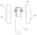
Fig. 2 is an enlarged schematic view of a portion a in fig. 1.
Fig. 3 is a right side view of the present invention.
Fig. 4 is a schematic structural diagram of a hoisting mechanism.
Fig. 5 is a schematic structural diagram of the movable pulley block.
Fig. 6 is a schematic view of the manner in which the steel cord is wound.
Fig. 7 is a schematic view of the locking device.
Detailed Description
It is right to combine the attached drawing below the utility model discloses do further to explain, the flue board vertically gets into the tunnel and the tunnel is advanced to the narrower one end of flue board promptly, and the flue board transversely gets into the tunnel and the tunnel is got into earlier to the one end of flue board broad promptly to the direction of initiative walking frame is the place ahead, and the direction of using from walking frame is the rear.
As shown in fig. 1-5, a tyre type lifting apparatus for a tunnel flue plate comprises two parallel walking beams 1 and a lifting mechanism, wherein the bottom of the front end of the walking beam 1 is rotatably connected with a driving walking frame 22, the driving walking frame 22 is fixedly connected with a driving motor 20, a transmission gear arranged on an output shaft of the driving motor 20 is engaged with a transmission gear arranged at the input end of a driving reducer 21, the transmission gear arranged at the output end of the driving reducer 21 is engaged with a transmission gear arranged on a walking wheel 16, the driving motor 20 is used for driving the walking wheel 16 to move forward or backward, the top of the driving walking frame 22 is fixedly connected with a steering gear 18, the steering gear 18 is rotatably connected to the bottom of the walking beam 1, the walking beam 1 is fixedly connected with a steering motor 17, the transmission gear arranged on the output shaft of the steering motor 17 is engaged with a transmission gear, the transmission gear at the output end of the steering reducer 19 is meshed with the steering gear 18, the steering motor 17 can adjust the advancing direction of the walking wheels 16 according to actual conditions, so that the movement of the hoisting equipment is more flexible, the driven walking frame 2 is fixedly connected to the bottom of the rear end of the walking beam 1, the walking wheels 16 are respectively and rotatably connected in the driving walking frame 22 and the driven walking frame 2, the walking wheels 16 adopt tires, tracks do not need to be laid in the tunnel 23, the working space in the tunnel 23 is not occupied, the buffers 13 are arranged at the front end of the driving walking frame 22 and the rear end of the driven walking frame 2, the track sweeping plates 14 are arranged below the buffers 13, and the buffers 13 can absorb impact force generated by impact when the equipment collides with the outside, therefore, equipment damage caused by collision is effectively protected, the rail sweeping plate 14 can effectively block large obstacles on the advancing route of the equipment, and the equipment is ensured to run stably.
The top of each walking beam 1 is fixedly connected with two supporting beams 3 respectively, the two supporting beams 3 are vertically arranged, a connecting beam 12 is fixedly connected between the supporting beams 3 on the same walking beam 1, the connecting beam 12 is also fixedly connected between the supporting beam 3 and the walking beam 1, the connecting beam 12 can enable the whole equipment to be more stable, the tops of the two walking beams 1 are symmetrically and fixedly connected with the two supporting beams 3 respectively, end beams 4 are fixedly connected between the corresponding supporting beams 3 on the two walking beams 1, and the two end beams 4 are arranged in parallel; the lifting mechanism comprises an adjusting frame 5 and a lifting frame 7, the electric hoist 6 is fixedly connected to the front end of the lifting frame 7, the rope winding device is arranged at the rear end of the lifting frame 7 and comprises a fixed pulley block 8 and a movable pulley block 9, the fixed pulley block 8 is positioned above the movable pulley block 9, the fixed pulley block 8 comprises a fixed pulley frame 801 and two fixed pulleys with axes perpendicular to each other, the fixed pulleys play a role in converting the direction of the steel wire rope, the two fixed pulleys are rotatably connected to the fixed pulley frame 801, the two fixed pulleys are respectively marked as a first fixed pulley 802 and a second fixed pulley 803, the fixed pulley frame 801 is further provided with a locking device for fixing the head of the steel wire rope, the locking device comprises a wedge-shaped hoop 805 and a wedge-shaped inserting plate 806 matched with the wedge-shaped hoop 805, the wedge-shaped hoop is fixedly connected to the fixed pulley frame 801, and the head of the steel wire rope is wound on the wedge-shaped inserting plate 806 and inserted into the wedge-; a lifting frame 7 is fixedly connected to the top of the end beam 4, a first slide way 701 is horizontally arranged in the lifting frame 7, the first slide way 701 is arranged in parallel with the walking beam 1, an adjusting frame 5 is connected with the first slide way 701 in a sliding manner, a first oil cylinder 502 for driving the adjusting frame 5 is fixedly connected to the lifting frame 7, the first oil cylinder 502 is arranged in parallel with the first slide way 701, the piston cylinder end of the first oil cylinder 502 is hinged to the adjusting frame 5, a second slide way 501 is horizontally arranged in the adjusting frame 5, the second slide way 501 is perpendicular to the first slide way 701, the fixed pulley frame 801 is connected with the second slide way 501 in a sliding manner, a second oil cylinder 804 for driving the fixed pulley frame 801 is fixedly connected to the adjusting frame 5, the second oil cylinder 804 is arranged in parallel with the second slide way 501, and the piston rod end of the second oil cylinder 804 is hinged to the fixed pulley; the movable pulley block 9 comprises two movable pulley plates 901 which are arranged in parallel, a fixed shaft 905 is fixedly connected between the movable pulley plates 901, one end of the fixed shaft 905 is rotatably connected with a first movable pulley 902, the other end of the fixed shaft 905 is rotatably connected with a second movable pulley 903, the central position of the fixed shaft 905 is rotatably connected with a connecting rod 904 which is vertically arranged downwards, and the bottom of the connecting rod 904 is fixedly connected with a lifting appliance 10.
The first fixed pulley 802 is located at the front end of the second fixed pulley 803, the first movable pulley 902 is located at the front end of the second movable pulley 903, the axis of the first fixed pulley 802 is parallel to the axis of the first movable pulley 902, the first fixed pulley 802 is directly above the first movable pulley 902, one end of a steel wire rope of the electric hoist 6 firstly bypasses the first fixed pulley 802, the direction of the steel wire rope is changed and then bypasses the first movable pulley 902, then the steel wire rope passes through the second fixed pulley 803 to change the direction and then bypasses the second movable pulley 903, and finally the steel wire rope is fixed and locked through the matching of the wedge-shaped inserting plate 806 and the wedge-shaped hoop 805, the electric hoist 6 can drive the movable pulley block 9 to move up and down, the first movable pulley 902 and the second movable pulley 903 are symmetrically arranged relative to the connecting rod 904, so that the stress balance of the steel wire rope can be ensured, meanwhile, the balance of a lifting appliance can be.
The utility model discloses an operating process is as follows, with flue plate 11 longitudinal fixity on hoist 10 earlier, then through electric block 6 and fixed pulley 8, the cooperation of running block 9, promote flue plate 11 to the mounting height, under the drive of driving motor 20, hoisting equipment begins to remove, stop moving when equipment removes mounted position, then staff's manual rotatory flue plate 11, with flue plate 11 rotatory to the transverse position, then first hydro-cylinder 502 of rethread and second hydro-cylinder 804 carry out the front and back to flue plate 11, fine setting about, realize flue plate 11's accurate installation. The motor, the oil cylinder and the like in the embodiment are all controlled by a controller, the controller is the existing mature technology, and detailed description of the controller is omitted in the embodiment.
The above-described embodiments are only some embodiments of the present invention, and not all embodiments, and all other embodiments obtained by those skilled in the art without any inventive work are within the scope of the present invention.
Claims (8)
1. The utility model provides a tire formula hoisting equipment of flue board for tunnel which characterized in that: the lifting mechanism comprises a lifting mechanism and two walking beams which are arranged in parallel, wherein a driving walking frame is arranged at the bottom of one end of each walking beam, a driving motor is arranged on the driving walking frame, a driven walking frame is fixedly connected to the bottom of the other end of each walking beam, walking wheels are respectively and rotatably connected in the driving walking frame and the driven walking frame, and the driving motor is in transmission connection with the walking wheels on the driving walking frame through a driving speed reducer; two walking beam tops are symmetry fixedly connected with a plurality of supporting beam respectively, fixedly connected with end beam between the supporting beam that corresponds on two walking beams, hoisting mechanism is including lifting the frame, lifting frame fixed connection is at end beam top, it is provided with electric block and wiring device on the lifting frame to lift, electric block fixed connection is in the one end that lifts to rise to put up close to a supporting beam, the one end of a supporting beam is kept away from at the lifting frame to the wiring device setting, fixed connection is on the wiring device behind the wiring device is walked around to electric block's wire rope's one end, the hoist is installed to the wiring device bottom.
2. The tyre-type lifting apparatus of a flue plate for a tunnel according to claim 1, wherein: the rope winding device comprises a fixed pulley block and a movable pulley block, the fixed pulley block is positioned above the movable pulley block, the fixed pulley block comprises a fixed pulley frame and two fixed pulleys with axes perpendicular to each other, the two fixed pulleys are rotatably connected to the fixed pulley frame, the two fixed pulleys are respectively marked as a first fixed pulley and a second fixed pulley, and the fixed pulley frame is also provided with a locking device for fixing a steel wire rope head; the movable pulley block comprises two movable pulley plates which are arranged in parallel, a fixed shaft is fixedly connected between the movable pulley plates, one end of the fixed shaft is rotatably connected with a first movable pulley, the other end of the fixed shaft is rotatably connected with a second movable pulley, the central position of the fixed shaft is rotatably connected with a connecting rod which is vertically and downwardly arranged, and the connecting rod is fixedly connected to the central position of the lifting appliance; one end of a steel wire rope on the electric hoist sequentially winds around the first fixed pulley, the first movable pulley, the second fixed pulley and the second movable pulley, and the rope end of the steel wire rope is fixed on the fixed pulley frame through the locking device.
3. The tyre-type lifting apparatus of a flue plate for a tunnel according to claim 2, wherein: the locking device comprises a wedge-shaped hoop and a wedge-shaped inserting plate matched with the wedge-shaped hoop, and the rope head of the steel wire rope is wound on the wedge-shaped inserting plate and inserted into the wedge-shaped hoop.
4. The tyre-type lifting apparatus of a flue plate for a tunnel according to claim 2, wherein: the lifting mechanism further comprises an adjusting frame, a first slide way is horizontally arranged in the lifting frame and is parallel to the walking beam, the adjusting frame is connected with the first slide way in a sliding mode, a first oil cylinder used for driving the adjusting frame is fixedly connected to the lifting frame, and the piston cylinder end of the first oil cylinder is hinged to the adjusting frame; a second slide way is horizontally arranged in the adjusting frame, the second slide way is perpendicular to the first slide way, the fixed pulley frame is in sliding connection with the second slide way, a second oil cylinder used for driving the fixed pulley frame is fixedly connected to the adjusting frame, and the piston rod end of the second oil cylinder is hinged to the fixed pulley frame.
5. The tyre-type lifting apparatus of a flue plate for a tunnel according to claim 1, wherein: the active walking frame is rotatably connected to the bottom of the walking beam, a steering gear is fixedly connected to the top of the active walking frame and rotatably connected with the active walking frame, a steering motor is fixedly connected to the walking beam, and the steering motor is in transmission connection with the steering gear through a steering speed reducer.
6. The tyre-type lifting apparatus of a flue plate for a tunnel according to claim 1, wherein: a plurality of connecting beams are fixedly connected between the supporting beams on the same walking beam, and a plurality of connecting beams are fixedly connected between the supporting beams and the walking beam where the supporting beams are located.
7. The tyre-type lifting apparatus of a flue plate for a tunnel according to claim 1, wherein: the end parts of the driving walking frame and the driven walking frame are provided with buffers, and rail sweeping plates are arranged below the buffers.
8. The tyre-type lifting apparatus of a flue plate for a tunnel according to claim 1, wherein: the road wheels are tires.
Priority Applications (1)
| Application Number | Priority Date | Filing Date | Title |
|---|---|---|---|
| CN202020061962.9U CN211393620U (en) | 2020-01-13 | 2020-01-13 | Tire type hoisting equipment of flue plate for tunnel |
Applications Claiming Priority (1)
| Application Number | Priority Date | Filing Date | Title |
|---|---|---|---|
| CN202020061962.9U CN211393620U (en) | 2020-01-13 | 2020-01-13 | Tire type hoisting equipment of flue plate for tunnel |
Publications (1)
| Publication Number | Publication Date |
|---|---|
| CN211393620U true CN211393620U (en) | 2020-09-01 |
Family
ID=72217607
Family Applications (1)
| Application Number | Title | Priority Date | Filing Date |
|---|---|---|---|
| CN202020061962.9U Expired - Fee Related CN211393620U (en) | 2020-01-13 | 2020-01-13 | Tire type hoisting equipment of flue plate for tunnel |
Country Status (1)
| Country | Link |
|---|---|
| CN (1) | CN211393620U (en) |
-
2020
- 2020-01-13 CN CN202020061962.9U patent/CN211393620U/en not_active Expired - Fee Related
Similar Documents
| Publication | Publication Date | Title |
|---|---|---|
| CN209988965U (en) | Automatic hoisting equipment for sleeper mold in and out of kiln | |
| CN202214152U (en) | Trolley walking traction mechanism of bridge crane | |
| CN109139065B (en) | Segment conveying system suitable for small curve turning of shield tunneling machine | |
| CN104060870B (en) | A kind of manipulator Transport Vehicle handling equipment | |
| CN212687158U (en) | Novel subway ring network cable wire barrow | |
| CN215801077U (en) | Pulley type cable saddle device | |
| CN202850551U (en) | Rapid two-layer lifting sidesway class stereo garage driven by motor-driven push rod | |
| CN211393620U (en) | Tire type hoisting equipment of flue plate for tunnel | |
| CN219029041U (en) | Wheel-rail dual-purpose multifunctional tunnel vehicle | |
| CN203419138U (en) | Novel viaduct accident road block removal rail car | |
| CN111017738A (en) | Tire type hoisting equipment of flue plate for tunnel | |
| CN108798714A (en) | A kind of working portable shifting formwork trolley of channel wall body and its construction method | |
| CN114275684A (en) | Self-service variable-span broken line supporting leg tire type lifting beam machine | |
| CN212450345U (en) | Railway vehicle wheel pair matching lifting manipulator | |
| CN212556235U (en) | Motor train unit vehicle bottom detection system | |
| CN212614733U (en) | Mobile platform and tunnel construction trolley | |
| CN211687992U (en) | Movable shield tunnel construction operation platform with lifting equipment | |
| CN1309610C (en) | Magnetic suspension track inspection railcar | |
| CN2592793Y (en) | Telescopic garage | |
| CN113982645B (en) | Needle beam type steel strand full section construction operation trolley | |
| CN105905804A (en) | Hybrid differential driving mechanism for controlling lifting of crane and transverse moving of trolley | |
| CN111532977A (en) | Gate-type ground is wall steel reinforcement cage hoist and mount hoisting apparatus even | |
| CN220059076U (en) | High-speed carrier | |
| CN220642297U (en) | Storage battery trackless portal frame | |
| CN103318199B (en) | Overpass accident is removed obstacles rail vehicle |
Legal Events
| Date | Code | Title | Description |
|---|---|---|---|
| GR01 | Patent grant | ||
| GR01 | Patent grant | ||
| CP01 | Change in the name or title of a patent holder |
Address after: 453400 Weizhuang Town Industrial Zone, Changyuan County, Xinxiang City, Henan Province Patentee after: Henan Tieshan lifting equipment Group Co.,Ltd. Address before: 453400 Weizhuang Town Industrial Zone, Changyuan County, Xinxiang City, Henan Province Patentee before: HENAN TIESHAN LIFTING EQUIPMENT Co.,Ltd. |
|
| CP01 | Change in the name or title of a patent holder | ||
| CF01 | Termination of patent right due to non-payment of annual fee |
Granted publication date: 20200901 Termination date: 20210113 |
|
| CF01 | Termination of patent right due to non-payment of annual fee |