CN211386958U - Novel precision boring cutter - Google Patents
Novel precision boring cutter Download PDFInfo
- Publication number
- CN211386958U CN211386958U CN202020034027.3U CN202020034027U CN211386958U CN 211386958 U CN211386958 U CN 211386958U CN 202020034027 U CN202020034027 U CN 202020034027U CN 211386958 U CN211386958 U CN 211386958U
- Authority
- CN
- China
- Prior art keywords
- cutter
- blank
- plane
- welding
- upper plane
- Prior art date
- Legal status (The legal status is an assumption and is not a legal conclusion. Google has not performed a legal analysis and makes no representation as to the accuracy of the status listed.)
- Active
Links
Images


Abstract
The utility model relates to a novel precision boring cutter, which comprises a cutter head and a cutter blank, wherein the front side of the cutter blank is provided with an end head, the cutter head is welded on the end head, the right side of the end head is connected with an arc transition surface, the arc transition surface extends to the upper plane of the cutter blank, the side edge of the cutter head is parallel and level with the left side edge of the cutter blank, the left side edge of the cutter blank extends downwards to the lower plane of the cutter blank, the upper plane of the cutter blank is provided with a clearance interference-proof workpiece, the right side of the clearance interference-proof workpiece is provided with a cutter body clamping part, the right side of the cutter body clamping part is provided with an acute angle positioning part, the end surface of the acute angle positioning part is provided with an acute angle positioning inclined plane with an included; the utility model has the advantages of realize the cutting of little aperture high hardness material, promote life, improve machining precision and efficiency, exploit cutter application range.
Description
Technical Field
The utility model relates to the technical field of machining, concretely relates to novel accurate boring cutter.
Background
At present, the existing boring cutters are generally divided into two types, one type is a machine clamp type which comprises a blade and a cutter handle, the whole volume of the machine clamp type is large, the cutter handle is long, and the aperture which can be processed is limited; the other is hard alloy, which improves the limitation of aperture, but has high price, short service life and limited hardness of processing material; therefore, it is necessary to provide a novel precision boring tool which can cut a material with a small bore diameter and high hardness, prolong the service life, improve the machining precision and efficiency, and expand the use range of the tool.
Disclosure of Invention
The utility model aims at overcoming the not enough of prior art, and provide a realize the cutting of little aperture high rigidity material, promote life, improve machining precision and efficiency, develop the novel accurate boring cutter of cutter application range.
The purpose of the utility model is realized like this: a novel precision boring cutter comprises a cutter head and a cutter blank, wherein the front side of the cutter blank is provided with an end, the contact surface of the cutter head and the end comprises a welding inner side surface, a welding upper plane and a welding lower plane, the welding inner side surface is perpendicular to the welding upper plane and the welding lower plane, the upper plane of the cutter head is parallel and level with the welding upper plane, the welding upper plane extends to an arc transition surface, the arc transition surface extends to the cutter blank upper plane, the side edge of the cutter head is parallel and level with the left side edge of the cutter blank, the left side edge of the cutter blank downwardly extends to the cutter blank lower plane, the cutter blank upper plane is provided with a space avoiding anti-interference workpiece, the right side of the space avoiding anti-interference workpiece is provided with a clamping cutter body, the right side of the cutter body clamping part is provided with an acute angle positioning part, the end surface of the positioning part is provided with an acute angle positioning inclined plane with a 30-degree included angle with the horizontal direction, the lower end of the acute angle positioning inclined plane is arranged above the lower plane of the knife blank.
The tool bit comprises a first cutting edge and a second cutting edge, an included angle of 5 degrees is formed between the side edge of the first cutting edge and the vertical direction, an included angle of 77.7-78 degrees is formed between the side edge of the first cutting edge and the side edge of the second cutting edge, and a fillet of R0.03-0.05mm is arranged at the deflection angle of the first cutting edge and the second cutting edge.
The cutter head adopts a PCBN blade, the angle A between the side edge of the cutter head and the vertical direction is 15-20 degrees, the thickness C of the cutter head is 0.75-0.95mm, and the diameter B of the superhard alloy bar required for preparing the cutter blank is 4-4.01 mm.
The shape of the space-avoiding interference-preventing workpiece is concave, the space-avoiding interference-preventing workpiece extends to the end leftwards, and the space-avoiding interference-preventing workpiece extends to the cutter body clamping part rightwards.
The upper side and the lower side of the cutter body clamping part are uniformly provided with clamping part side faces, and the acute angle positioning inclined plane is arc-connected with the clamping part side faces.
The utility model has the advantages that: the utility model adopts PCBN blade, which can realize the cutting of high hardness material, the design of the tool bit can greatly improve the service life, and effectively ensure the processing precision and roughness of the workpiece; by adopting reasonable cutter blank design, the cutting of a workpiece with an ultra-small aperture is realized, the cutter can be positioned in multiple directions, the clamping state of the cutter is limited in multiple directions, the cutter is ensured not to be displaced when in use, the cutter vibration phenomenon is reduced, and the processing stability and efficiency are improved; the reasonable design of the thickness of the cutter head and the diameter of the cutter blank bar is adopted, so that the high-hardness machining and the stability of the cutter body are ensured; the problems of limited aperture, short service life, low processing precision, low use efficiency and the like in the prior art are solved; the utility model has the advantages of realize the cutting of little aperture high hardness material, promote life, improve machining precision and efficiency, exploit cutter application range.
Drawings
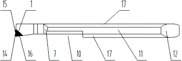
Fig. 1 is a schematic structural diagram of the novel precision boring tool of the present invention.
Fig. 2 is a top view of the novel precision boring tool of the present invention.
Fig. 3 is a design drawing of the thickness of the tool bit and the thickness of the bar material of the novel precise boring tool.
In the figure, the cutter head 2, the cutter blank 3, the end 4, the welding inner side surface 5, the welding upper plane 6, the welding lower plane 7, the arc transition surface 8, the cutter blank upper plane 9, the cutter blank lower plane 10, the space-avoiding interference-preventing workpiece 11, the cutter body clamping part 12, the acute angle positioning part 13, the acute angle positioning inclined plane 14, the cutter head fillet 15, the first cutting edge 16, the second cutting edge 17, the clamping part side surface A, the cutter head inclined plane angle B, the cutter blank bar diameter C and the cutter head thickness are shown.
Detailed Description
The present invention will be further described with reference to the accompanying drawings.
Example 1
As shown in fig. 1-3, a novel precision boring tool comprises a tool bit 1 and a tool blank 2, wherein a tip 3 is arranged on the front side of the tool blank 2, a contact surface between the tool bit 1 and the tip 3 comprises a welding inner side surface 4, a welding upper plane 5 and a welding lower plane 6, the welding inner side surface 4 is perpendicular to the welding upper plane 5 and the welding lower plane 6, the upper plane of the tool bit 1 is flush with the welding upper plane 5, the welding upper plane 5 extends to an arc transition surface 7, the arc transition surface 7 extends to a tool blank upper plane 8, the side edge of the tool bit 1 is flush with the left side edge of the tool blank 2, the left side edge of the tool blank 2 extends downwards to a tool blank lower plane 9, the tool blank upper plane 8 is provided with a clearance interference prevention workpiece 10, and the right side of the clearance interference prevention workpiece 10 is provided with a tool body clamping part 11, the right side of the cutter body clamping part 11 is provided with an acute angle positioning part 12, the end surface of the acute angle positioning part 12 is provided with an acute angle positioning inclined plane 13 with an included angle of 30 degrees with the horizontal direction, and the lower end of the acute angle positioning inclined plane 13 is arranged above the cutter blank lower plane 9.
The utility model selects the upper plane of the fine grinding wheel mill tool bit 1 to be parallel and level with the welding upper plane 5, thus ensuring the flatness of the upper plane of the tool bit 1, reducing the problems of jumping edges, openings and the like and prolonging the service life of the tool; the clearance-avoiding interference-preventing workpiece 10 is adopted, so that special avoidance can be performed when the workpiece with the extra-small aperture is cut, and the cutting of the workpiece with the extra-small aperture is realized; the acute angle positioning part 12 with the acute angle positioning inclined plane 13 is adopted, so that the cutter can be accurately and effectively fixed, the problems of cutter vibration, rotation and the like can not occur in the high-precision machining process, and the machining precision and the machining efficiency are improved; the utility model has the advantages of realize the cutting of little aperture high hardness material, promote life, improve machining precision and efficiency, exploit cutter application range.
Example 2
As shown in fig. 1-3, a novel precision boring tool comprises a tool bit 1 and a tool blank 2, wherein a tip 3 is arranged on the front side of the tool blank 2, a contact surface between the tool bit 1 and the tip 3 comprises a welding inner side surface 4, a welding upper plane 5 and a welding lower plane 6, the welding inner side surface 4 is perpendicular to the welding upper plane 5 and the welding lower plane 6, the upper plane of the tool bit 1 is flush with the welding upper plane 5, the welding upper plane 5 extends to an arc transition surface 7, the arc transition surface 7 extends to a tool blank upper plane 8, the side edge of the tool bit 1 is flush with the left side edge of the tool blank 2, the left side edge of the tool blank 2 extends downwards to a tool blank lower plane 9, the tool blank upper plane 8 is provided with a clearance interference prevention workpiece 10, and the right side of the clearance interference prevention workpiece 10 is provided with a tool body clamping part 11, the right side of the cutter body clamping part 11 is provided with an acute angle positioning part 12, the end surface of the acute angle positioning part 12 is provided with an acute angle positioning inclined plane 13 with an included angle of 30 degrees with the horizontal direction, and the lower end of the acute angle positioning inclined plane 13 is arranged above the cutter blank lower plane 9.
The tool bit 1 comprises a first cutting edge 15 and a second cutting edge 16, an included angle of 5 degrees is formed between the side edge of the first cutting edge 15 and the vertical direction, an included angle of 77.7-78 degrees is formed between the side edge of the first cutting edge 15 and the side edge of the second cutting edge 16, the machining efficiency is greatly improved, and a fillet of R0.03-0.05mm is arranged at the deflection angle of the first cutting edge 15 and the second cutting edge 16, so that the machining precision and the roughness are effectively ensured.
The cutter head 1 adopts a PCBN blade, the angle A between the side edge of the cutter head 1 and the vertical direction is 15-20 degrees, the thickness C of the cutter head 1 is 0.75-0.95mm, the diameter B of a superhard alloy bar required for preparing the cutter blank 2 is 4-4.01mm, and high-hardness processing and the stability of the cutter body are ensured.
The shape of the space-avoiding interference-preventing workpiece 10 is concave, the space-avoiding interference-preventing workpiece 10 extends to the end 3 leftwards, the space-avoiding interference-preventing workpiece 10 extends to the cutter body clamping part 11 rightwards, and can avoid when the workpiece with the ultra-small aperture is cut, so that the workpiece with the ultra-small aperture is cut.
The upper side and the lower side of the cutter body clamping part 11 are uniformly provided with clamping part side surfaces 17, and the acute angle positioning inclined surface 13 is in arc connection with the clamping part side surfaces 17, so that a cutter can be accurately and effectively fixed, and the problems of cutter vibration, rotation and the like cannot occur in the high-precision machining process.
The utility model discloses a tool bit 1 adopts the PCBN blade, can realize the cutting of high rigidity material, and the design of tool bit 1 can promote its life greatly, the machining precision and the roughness of effectual assurance work piece; by adopting the reasonable design of the cutter blank 2, the cutting of a workpiece with a very small aperture is realized, the cutter can be positioned in multiple directions, the clamping state of the cutter can be limited in multiple directions, the cutter is ensured not to be displaced when in use, the cutter vibration phenomenon is reduced, and the processing stability and efficiency are improved; the reasonable design of the tool bit thickness C and the tool blank bar diameter B is adopted, so that the high-hardness machining and the stability of the tool body are ensured; the problems of limited aperture, short service life, low processing precision, low use efficiency and the like in the prior art are solved; the utility model has the advantages of realize the cutting of little aperture high hardness material, promote life, increase machining precision, improve machining efficiency, develop cutter application range.
Claims (5)
1. The utility model provides a novel accurate boring cutter, it includes tool bit and sword base, its characterized in that: the front side of the knife blank is provided with an end, the contact surface of the knife head and the end comprises a welding inner side surface, a welding upper plane and a welding lower plane, the welding inner side surface is perpendicular to the welding upper plane and the welding lower plane, the upper plane of the knife head is parallel and level with the welding upper plane, the welding upper plane extends to an arc transition surface, the arc transition surface extends to the knife blank upper plane, the side edge of the knife head is parallel and level with the left side edge of the knife blank, the left side edge of the knife blank extends downwards to the knife blank lower plane, the knife blank upper plane is provided with a space-avoiding interference-preventing workpiece, the right side of the space-avoiding interference-preventing workpiece is provided with a clamping part, the right side of the knife body clamping part is provided with an acute angle positioning part, the end surface of the acute angle positioning part is provided with an acute angle positioning inclined plane with an included angle of 30 degrees with the horizontal direction, the lower end of the acute angle positioning inclined plane is arranged above the lower plane of the knife blank.
2. The novel precision boring tool as set forth in claim 1, wherein: the tool bit comprises a first cutting edge and a second cutting edge, an included angle of 5 degrees is formed between the side edge of the first cutting edge and the vertical direction, an included angle of 77.7-78 degrees is formed between the side edge of the first cutting edge and the side edge of the second cutting edge, and a fillet of R0.03-0.05mm is arranged at the deflection angle of the first cutting edge and the second cutting edge.
3. The novel precision boring tool as set forth in claim 2, wherein: the cutter head adopts a PCBN blade, the angle A between the side edge of the cutter head and the vertical direction is 15-20 degrees, the thickness C of the cutter head is 0.75-0.95mm, and the diameter B of the superhard alloy bar required for preparing the cutter blank is 4-4.01 mm.
4. The novel precision boring tool as set forth in claim 1, wherein: the shape of the space-avoiding interference-preventing workpiece is concave, the space-avoiding interference-preventing workpiece extends to the end leftwards, and the space-avoiding interference-preventing workpiece extends to the cutter body clamping part rightwards.
5. The novel precision boring tool as set forth in claim 1, wherein: the upper side and the lower side of the cutter body clamping part are uniformly provided with clamping part side faces, and the acute angle positioning inclined plane is arc-connected with the clamping part side faces.
Priority Applications (1)
| Application Number | Priority Date | Filing Date | Title |
|---|---|---|---|
| CN202020034027.3U CN211386958U (en) | 2020-01-08 | 2020-01-08 | Novel precision boring cutter |
Applications Claiming Priority (1)
| Application Number | Priority Date | Filing Date | Title |
|---|---|---|---|
| CN202020034027.3U CN211386958U (en) | 2020-01-08 | 2020-01-08 | Novel precision boring cutter |
Publications (1)
| Publication Number | Publication Date |
|---|---|
| CN211386958U true CN211386958U (en) | 2020-09-01 |
Family
ID=72219378
Family Applications (1)
| Application Number | Title | Priority Date | Filing Date |
|---|---|---|---|
| CN202020034027.3U Active CN211386958U (en) | 2020-01-08 | 2020-01-08 | Novel precision boring cutter |
Country Status (1)
| Country | Link |
|---|---|
| CN (1) | CN211386958U (en) |
-
2020
- 2020-01-08 CN CN202020034027.3U patent/CN211386958U/en active Active
Similar Documents
| Publication | Publication Date | Title |
|---|---|---|
| CN105563062A (en) | Machining method for hard-alloy turning tool | |
| CN201483087U (en) | Gun reamer for machining valve guide bore | |
| JP2009119572A (en) | Insert and edge replaceable cutting tool | |
| CN211386958U (en) | Novel precision boring cutter | |
| CN104227093A (en) | Drill point centering countersinking cutter | |
| CN218460881U (en) | Small hole boring cutter with end face blade | |
| CN111604510B (en) | Combined tool for machining stainless steel deep groove | |
| CN213002692U (en) | Indexable mechanically-clamped combined tool | |
| CN212384690U (en) | Mechanically-clamped groove milling cutter | |
| CN204893064U (en) | Key -way tool | |
| CN210937335U (en) | Cutting insert and tool for square shoulder milling | |
| CN202155544U (en) | Pin hole processing boring cutter | |
| CN219402483U (en) | Milling cutter for wheel blank positioning surface | |
| CN215880760U (en) | PCD milling cutter clamp with chip breaker groove | |
| CN2829941Y (en) | Cutting tools | |
| CN211727658U (en) | Indexable end milling cutter blade with arc head | |
| CN213614536U (en) | Accurate slitting saw of industry aluminium alloy | |
| CN111843008B (en) | Mechanically clamped groove milling cutter | |
| CN110640168A (en) | Combined turning tool with adjustable center | |
| CN220739489U (en) | Multifunctional damping cutter for machining annular deep groove of rotary workpiece | |
| CN213002682U (en) | Circular groove cutter | |
| CN211162091U (en) | PCD annular cutter | |
| CN204159944U (en) | Apex point centering countersink | |
| CN212443411U (en) | Cutter for machining double-clamp-spring groove | |
| CN210755234U (en) | Split type welding boring cutter |
Legal Events
| Date | Code | Title | Description |
|---|---|---|---|
| GR01 | Patent grant | ||
| GR01 | Patent grant |