CN211386018U - Cleaning device - Google Patents
Cleaning device Download PDFInfo
- Publication number
- CN211386018U CN211386018U CN201922189141.3U CN201922189141U CN211386018U CN 211386018 U CN211386018 U CN 211386018U CN 201922189141 U CN201922189141 U CN 201922189141U CN 211386018 U CN211386018 U CN 211386018U
- Authority
- CN
- China
- Prior art keywords
- cleaning
- transfer
- assembly
- cleaned
- moving
- Prior art date
- Legal status (The legal status is an assumption and is not a legal conclusion. Google has not performed a legal analysis and makes no representation as to the accuracy of the status listed.)
- Active
Links
Images


Landscapes
- Cleaning By Liquid Or Steam (AREA)
- Cleaning In General (AREA)
Abstract
The utility model discloses a cleaning device, which comprises a transfer mechanism (100), a spraying mechanism (200) and a drying mechanism (300); the transfer mechanism (100) is arranged to receive the object to be cleaned and transfer the object to be cleaned to a cleaning station S; the spraying mechanism (200) comprises a sprayer (201) positioned above the cleaning station S, and the sprayer (201) is arranged to be capable of moving along a first direction to spray cleaning liquid to the object to be cleaned; the drying mechanism (300) comprises an air knife (301) positioned above the cleaning station S, and the air knife (301) is arranged to be capable of moving along the second direction to provide high-pressure air flow for the object to be cleaned. The utility model discloses a cleaning device has compact structure, clean efficient advantage.
Description
Technical Field
The utility model relates to a glass processing technology field specifically relates to a cleaning device.
Background
At present, the substrate glass produced by the float process is generally subjected to surface polishing, so that surface scratches and impurities are eliminated, and the surface waviness is reduced. Existing glass polishing equipment cleans the glass during operation to remove debris from the glass surface and to clean the glass. However, the existing glass polishing equipment generally has the problems of large occupied space and low cleaning efficiency.
SUMMERY OF THE UTILITY MODEL
The utility model aims at overcoming the problem that prior art exists, provide a cleaning device, this cleaning device has compact structure, clean efficient advantage.
In order to achieve the above object, the present invention provides a cleaning apparatus, which includes a transfer mechanism, a spray mechanism, and a drying mechanism; the transfer mechanism is arranged to receive the object to be cleaned and transfer the object to be cleaned to a cleaning station S; the spraying mechanism comprises a sprayer positioned above the cleaning station S, and the sprayer is arranged to be capable of moving along a first direction so as to spray cleaning liquid to the object to be cleaned; the drying mechanism comprises an air knife positioned above the cleaning station S, and the air knife is arranged to be capable of moving along the second direction so as to provide high-pressure air flow for the object to be cleaned.
Optionally, the cleaning station S is disposed horizontally, and the first direction is the same as the second direction and is disposed horizontally.
Optionally, the spraying mechanism includes a first moving assembly arranged along the first direction, the first moving assembly includes a first moving member arranged above the cleaning station S and capable of moving along the first direction, and the sprayer is arranged on the first moving member; the drying mechanism comprises a second moving assembly arranged along the second direction, the second moving assembly is parallel to the first moving assembly, the second moving assembly comprises a second moving member arranged above the cleaning station S and capable of moving along the second direction, and the air knife is arranged on the second moving member.
Optionally, the first moving member is located in front of the second moving member in the first direction.
Optionally, the transfer mechanism includes a conveying assembly extending along a first direction, and the conveying assembly extends through the cleaning station S and is configured to transfer the object to be cleaned along the first direction.
Optionally, the transfer mechanism comprises a plurality of idler wheels, and the idler wheels are arranged along the first direction and arranged at two sides of the conveying assembly to prevent the object to be cleaned from falling off the conveying assembly.
Optionally, the conveying assembly comprises a motor, a conveying chain and a plurality of chain wheels and a plurality of conveying rollers; the conveying rollers are arranged in the first direction, and each conveying roller is perpendicular to the first direction; every the tip of transfer roller is equipped with one the sprocket, the conveying chain is with a plurality of sprocket cooperation and by motor drive is in order to order about a plurality of the transfer roller is rotatory around self axis.
Optionally, the conveying assembly comprises a plurality of water retaining covers matched with the conveying rollers, each water retaining cover is provided with a through hole, one end of each conveying roller penetrates through one through hole of each water retaining cover and extends into the water retaining cover, and the chain wheel is arranged on the end portion of the conveying roller in the water retaining cover.
Optionally, the conveying assembly comprises a plurality of water retaining rings, and each water retaining ring is correspondingly arranged between the through hole of the water retaining cover and the chain wheel.
Optionally, the transfer mechanism, the spray mechanism and the drying mechanism form a cleaning assembly; the cleaning equipment comprises a rack, a plurality of layers of accommodating spaces which are arranged in the vertical direction are defined in the rack, the cleaning equipment comprises a plurality of cleaning assemblies, and one cleaning assembly is arranged in each layer of accommodating space; the transfer mechanisms of the adjacent accommodating spaces transfer the objects to be cleaned in opposite directions.
According to the technical scheme, the object to be cleaned is received by the transfer mechanism and transferred to the cleaning station S by the transfer mechanism, the sprayer of the spraying mechanism moves along the first direction to spray cleaning liquid to the object to be cleaned at the cleaning station S, and after the cleaning liquid cleans the object to be cleaned, the air knife of the drying mechanism moves along the second direction to provide high-pressure air flow for the object to be cleaned so as to blow off the cleaning liquid on the surface of the object to be cleaned, so that the drying work is completed. In foretell clean in-process, treat that the cleaner is located all the time clean station S department, it is different from prior art needs will treat that the cleaner constantly changes the station in order to realize clear mode, the utility model discloses a cleaning equipment can make and treat that the cleaner is in clean station S department and accomplish cleaning all the time, therefore has compact structure, clean efficient advantage.
Drawings
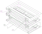
FIG. 1 is a schematic view of an embodiment of a cleaning apparatus of the present invention;
FIG. 2 is a longitudinal section of FIG. 1;
FIG. 3 is a front view of FIG. 1;
FIG. 4 is an enlarged schematic view of portion A of FIG. 3;
fig. 5 is a schematic structural view of a transfer mechanism of the cleaning device of the present invention.
Detailed Description
The following detailed description of the embodiments of the present invention will be made with reference to the accompanying drawings. It is to be understood that the description of the embodiments herein is for purposes of illustration and explanation only and is not intended to limit the invention.
As shown in fig. 1 to 5, the cleaning device of the present invention includes a transfer mechanism 100, a spray mechanism 200, and a drying mechanism 300; the transfer mechanism 100 is arranged to receive the object to be cleaned and transfer the object to be cleaned to the cleaning station S; the spraying mechanism 200 comprises a sprayer 201 positioned above the cleaning station S, and the sprayer 201 is arranged to be capable of moving along a first direction to spray cleaning liquid to an object to be cleaned; the drying mechanism 300 includes an air knife 301 located above the cleaning station S, and the air knife 301 is disposed to be movable in the second direction to provide a high-pressure air flow to the object to be cleaned.
The utility model discloses in, treat that the cleaner is received by transfer mechanism 100 and is transferred to clean station S by transfer mechanism 100, at this clean station S, spray mechanism 200 'S spray 201 and remove along the first direction in order to spray the washing liquid to treating the cleaner, treat the cleaner at the washing liquid and wash after, dry mechanism 300' S air knife 301 removes along the second direction in order to provide high-pressure draught to treating the cleaner and will treat the washing liquid on cleaner surface and blow off to accomplish drying work. In foretell clean in-process, treat that the cleaning object is located clean station S department all the time, it is different from prior art needs will treat that the cleaning object constantly changes the station in order to realize clear mode, the utility model discloses a cleaning equipment can make and treat that the cleaning object is in clean station S department and accomplish cleaning all the time, therefore has compact structure, clean efficient advantage.
It should be understood that the cleaning station S can be disposed at various angles, for example, the cleaning station S can be disposed vertically, and correspondingly, the object to be cleaned is disposed vertically and adsorbed on the cleaning station S. In order to more conveniently move the object to be cleaned to the cleaning station S and stably keep the object to be cleaned on the cleaning station S, in an embodiment of the present invention, optionally, the cleaning station S is horizontally disposed, and the first direction is the same as the second direction and is horizontally disposed. In this embodiment, the spraying mechanism 200 and the drying mechanism 300 are both disposed right above the cleaning station S, the sprayer 201 sprays the cleaning solution onto the object to be cleaned on the cleaning station S from top to bottom, and the air knife 301 also provides the high-pressure air flow to the object to be cleaned from top to bottom.
The spraying mechanism 200 can have various forms to realize the movement of the sprayer 201 in the first direction, and the drying mechanism 300 can also have various forms to realize the movement of the air knife 301 in the second direction, specifically, the spraying mechanism 200 comprises a first moving assembly 202 arranged in the first direction, the first moving assembly 202 comprises a first moving member arranged above the cleaning station S and capable of moving in the first direction, and the sprayer 201 is arranged on the first moving member; the drying mechanism 300 includes a second moving assembly 302 disposed along a second direction, the second moving assembly 302 is parallel to the first moving assembly 202, the second moving assembly 302 includes a second moving member disposed above the cleaning station S and capable of moving along the second direction, and the air knife 301 is disposed on the second moving member. For example, the first moving assembly 202 may be a hydraulic cylinder, the first moving member is a piston rod of the hydraulic cylinder, the shower 201 is disposed at an end of the piston rod, and the second moving assembly 302 may be a cylinder, the second moving member is a pneumatic rod of the cylinder, and the air knife 301 is disposed at an end of the pneumatic rod. The utility model discloses an in an embodiment, first removal subassembly 202 is the first straight line module that sets up along the first direction, and first moving member is the first slip table of first straight line module, and spray thrower 201 sets up on first slip table, and second removal subassembly 302 is the second straight line module parallel with first straight line module, and the second moving member is the second slip table of second straight line module, and air knife 301 sets up on the second slip table.
In the above embodiment, the first moving assembly 202 and the second moving assembly 302 can be controlled by the control mechanism respectively, so as to realize various movement coordination of the sprayer 201 and the air knife 301. For example, the control mechanism can control the first moving component 202 to start first, the first moving component drives the sprayer 201 to reciprocate so as to spray the object to be cleaned for multiple times, after the spraying is finished, the control mechanism controls the first moving component 202 to stop and controls the second moving component 302 to start, and the second moving component drives the air knife 301 to reciprocate so as to dry the object to be cleaned for multiple times. In order to improve the cleaning efficiency as much as possible and effectively reduce the cleaning cost, optionally, the first moving member is located in front of the second moving member along the first direction, that is, the control mechanism can control the first moving assembly 202 and the second moving assembly 302 to be simultaneously started and the first moving member is located in front of the second moving member, so that the high-pressure air flow provided by the air knife 301 is immediately followed by the cleaning liquid provided by the sprayer 201, that is, the cleaning liquid is blown away by the high-pressure air flow immediately after the surface of the object to be cleaned is washed, and the first moving member and the second moving member only move in a single pass, thereby greatly reducing the cleaning time and improving the cleaning efficiency.
In order to further save the floor space, the transfer mechanism 100 may optionally include a conveying assembly extending in the first direction, the conveying assembly extending through the cleaning station S and configured to transfer the object to be cleaned in the first direction. In other words, the cleaning station S is located on the conveying assembly, and the object to be cleaned can pass through the cleaning station S when moving on the conveying assembly, and the object to be cleaned can be stopped at the cleaning station S only by stopping the operation of the conveying assembly.
In order to prevent the cleaning object from falling off the transfer assembly when being transferred, the transfer mechanism 100 may optionally include a plurality of idler wheels 104, and the plurality of idler wheels 104 may be arranged in a first direction and disposed at both sides of the transfer assembly to prevent the cleaning object from falling off the transfer assembly.
It should be understood that the transfer assembly can be designed in various forms, and in one embodiment of the present invention, the transfer assembly can optionally include a motor, a transfer chain, and a plurality of sprockets and a plurality of transfer rollers 101; the conveying rollers 101 are arranged in a first direction, and each conveying roller 101 is perpendicular to the first direction; the end of each transfer roller 101 is provided with a sprocket, and the transfer chain is engaged with the plurality of sprockets and driven by a motor to rotate the plurality of transfer rollers 101 about their own axes. That is, the plurality of conveying rollers 101 are rotated in synchronization so as to drive the object to be cleaned to pass through each of the conveying rollers 101 in turn, i.e., to move in the first direction to the cleaning station S.
In order to prevent the cleaning liquid from affecting the sprocket and the bearing for supporting the conveying roller 101, optionally, the conveying assembly includes a plurality of water-retaining covers 102 engaged with the plurality of conveying rollers 101, each water-retaining cover 102 has a through hole, one end of each conveying roller 101 passes through the through hole of one water-retaining cover 102 to extend into the water-retaining cover 102, and the sprocket is mounted on the end of the conveying roller 101 located in the water-retaining cover 102, that is, the water-retaining cover 102 covers the bearing therein, thereby preventing the cleaning liquid from splashing on the bearing.
In order to further prevent the cleaning liquid from affecting the sprocket and the bearing for supporting the conveying roller 101, the conveying assembly optionally includes a plurality of water guards 103, and each water guard 103 is correspondingly disposed between the through hole of the water guard 102 and the sprocket. A water deflector 103 is also provided at the other end of the conveying roller 101, and as shown in fig. 4, the water deflector 103 is provided between the through hole of the water deflector 102 and the bearing.
In order to clean a plurality of objects to be cleaned simultaneously and improve the cleaning efficiency, optionally, the transfer mechanism 100, the spray mechanism 200 and the drying mechanism 300 form a cleaning assembly; the cleaning device comprises a rack 400, wherein a plurality of layers of accommodating spaces which are arranged in the vertical direction are defined in the rack 400, the cleaning device comprises a plurality of cleaning components, and each layer of accommodating space is provided with one cleaning component; wherein, the transfer mechanisms 100 of the adjacent accommodating spaces transfer the objects to be cleaned in opposite directions.
The utility model discloses an in an embodiment, cleaning device is used for glass processing system, and wherein, multilayer accommodation space includes upper space and lower floor's space that upper and lower adjacent set up in pairs, and the transfer mechanism 100 in upper space sets up to be used for transferring glass, and the transfer mechanism 100 in lower floor's space sets up to be used for transferring the glass tray. Set up like this and make the utility model discloses a cleaning device can greatly improve in the glass processing flow to the clear efficiency of glass, promptly, the glass that bears through the glass tray can get into next process after being clean in upper space, and the empty glass tray of accomplishing the bearing work then is cleaned in lower space, makes preparation for bearing glass once more.
The preferred embodiments of the present invention have been described in detail with reference to the accompanying drawings, but the present invention is not limited thereto. In the technical idea scope of the present invention, it is possible to provide a solution of the present invention with a plurality of simple modifications to avoid unnecessary repetition, and the present invention is not described separately for various possible combinations. These simple variations and combinations should also be considered as disclosed in the present invention, all falling within the scope of protection of the present invention.
Claims (10)
1. A cleaning apparatus, characterized in that the cleaning apparatus comprises a transfer mechanism (100), a spray mechanism (200), and a drying mechanism (300);
the transfer mechanism (100) is arranged to receive the object to be cleaned and transfer the object to be cleaned to a cleaning station S;
the spraying mechanism (200) comprises a sprayer (201) positioned above the cleaning station S, and the sprayer (201) is arranged to be capable of moving along a first direction to spray cleaning liquid to the object to be cleaned;
the drying mechanism (300) comprises an air knife (301) positioned above the cleaning station S, and the air knife (301) is arranged to be capable of moving along a second direction to provide high-pressure air flow for the object to be cleaned.
2. The cleaning apparatus of claim 1, wherein the cleaning station S is horizontally disposed, and the first direction is the same as the second direction and is horizontally disposed.
3. The cleaning apparatus according to claim 2, characterized in that the spray mechanism (200) comprises a first moving assembly (202) disposed in the first direction, the first moving assembly (202) comprising a first moving member disposed above the cleaning station S and movable in the first direction, the sprayer (201) being disposed on the first moving member;
the drying mechanism (300) comprises a second moving assembly (302) arranged along the second direction, the second moving assembly (302) is parallel to the first moving assembly (202), the second moving assembly (302) comprises a second moving member arranged above the cleaning station S and capable of moving along the second direction, and the air knife (301) is arranged on the second moving member.
4. The cleaning apparatus as claimed in claim 3, wherein the first moving member is located forward of the second moving member in the first direction.
5. The cleaning apparatus according to claim 1, wherein the transfer mechanism (100) comprises a transfer assembly extending in a first direction, the transfer assembly extending through the cleaning station S and being arranged to be able to transfer the object to be cleaned in the first direction.
6. The cleaning apparatus according to claim 5, wherein the transfer mechanism (100) includes a plurality of idler wheels (104), the plurality of idler wheels (104) being arranged in the first direction and disposed on both sides of the conveying assembly to prevent the object to be cleaned from falling off the conveying assembly.
7. The cleaning apparatus according to claim 5, wherein the transport assembly comprises a motor, a transport chain and a plurality of sprockets and a plurality of transport rollers (101); the conveying rollers (101) are arranged in the first direction, and each conveying roller (101) is perpendicular to the first direction; every the tip of transfer roller (101) is equipped with one the sprocket, the transfer chain with a plurality of the sprocket cooperation and by the motor drive is in order to order about a plurality of transfer roller (101) are rotatory around self axis.
8. The cleaning device as claimed in claim 7, wherein the conveying assembly comprises a plurality of water-blocking covers (102) matched with a plurality of conveying rollers (101), each water-blocking cover (102) is provided with a through hole, one end of each conveying roller (101) penetrates through the through hole of one water-blocking cover (102) and extends into the water-blocking cover (102), and the chain wheel is installed on the end part of the conveying roller (101) located in the water-blocking cover (102).
9. The cleaning apparatus according to claim 8, wherein the transfer assembly comprises a plurality of water deflector rings (103), each water deflector ring (103) being correspondingly disposed between the through hole of the water deflector cover (102) and the sprocket.
10. The cleaning apparatus according to any one of claims 1 to 9, wherein the transfer mechanism (100), the shower mechanism (200), and the drying mechanism (300) constitute a cleaning assembly;
the cleaning device comprises a rack (400), wherein a plurality of layers of accommodating spaces which are arranged in the vertical direction are defined in the rack (400), the cleaning device comprises a plurality of cleaning assemblies, and one cleaning assembly is arranged in each layer of accommodating space; wherein, the directions of transferring the objects to be cleaned by the transferring mechanisms (100) of the adjacent accommodating spaces are opposite.
Priority Applications (1)
| Application Number | Priority Date | Filing Date | Title |
|---|---|---|---|
| CN201922189141.3U CN211386018U (en) | 2019-12-09 | 2019-12-09 | Cleaning device |
Applications Claiming Priority (1)
| Application Number | Priority Date | Filing Date | Title |
|---|---|---|---|
| CN201922189141.3U CN211386018U (en) | 2019-12-09 | 2019-12-09 | Cleaning device |
Publications (1)
| Publication Number | Publication Date |
|---|---|
| CN211386018U true CN211386018U (en) | 2020-09-01 |
Family
ID=72207556
Family Applications (1)
| Application Number | Title | Priority Date | Filing Date |
|---|---|---|---|
| CN201922189141.3U Active CN211386018U (en) | 2019-12-09 | 2019-12-09 | Cleaning device |
Country Status (1)
| Country | Link |
|---|---|
| CN (1) | CN211386018U (en) |
Cited By (2)
| Publication number | Priority date | Publication date | Assignee | Title |
|---|---|---|---|---|
| CN112058759A (en) * | 2020-09-04 | 2020-12-11 | 杨秉霖 | Automatic cleaning equipment for machining bearing seat of wind power generation equipment |
| CN112827877A (en) * | 2021-01-12 | 2021-05-25 | 南京罗朗智合电子科技有限公司 | Building glass surface dust removal robot and glass surface dust removal method |
-
2019
- 2019-12-09 CN CN201922189141.3U patent/CN211386018U/en active Active
Cited By (3)
| Publication number | Priority date | Publication date | Assignee | Title |
|---|---|---|---|---|
| CN112058759A (en) * | 2020-09-04 | 2020-12-11 | 杨秉霖 | Automatic cleaning equipment for machining bearing seat of wind power generation equipment |
| CN112058759B (en) * | 2020-09-04 | 2021-08-24 | 山东国创精密机械有限公司 | Automatic cleaning equipment for machining bearing seat of wind power generation equipment |
| CN112827877A (en) * | 2021-01-12 | 2021-05-25 | 南京罗朗智合电子科技有限公司 | Building glass surface dust removal robot and glass surface dust removal method |
Similar Documents
| Publication | Publication Date | Title |
|---|---|---|
| KR102147328B1 (en) | Cleaning system | |
| CN211386018U (en) | Cleaning device | |
| CN109967297A (en) | A kind of Furniture panel Full-automatic paint spraying production line | |
| CN207805871U (en) | A kind of Furniture panel Full-automatic paint spraying production line | |
| CN114023674B (en) | Lead frame surface treatment device based on integrated circuit | |
| CN106424049A (en) | Inverted intermittent bottle washing machine | |
| EP1140381B1 (en) | Rinsing device | |
| CN206613778U (en) | A kind of glass vertical cleaning device | |
| CN108160647B (en) | CG cleaning equipment | |
| JPH10189528A (en) | Apparatus and method for cleaning of substrate | |
| CN206122234U (en) | Transmission housing automatic cleaning machine | |
| CN111421125A (en) | Device and method for quickly processing surface of die casting | |
| CN214683056U (en) | Glass cleaning device | |
| CN220879680U (en) | Cleaning tool for automobile parts | |
| KR0186043B1 (en) | Method for scrubbing and cleaning substrate | |
| KR101634186B1 (en) | Cleaning apparatus for plate type material surface and cleaning method thereof | |
| CN114769201A (en) | Bearing ring production belt cleaning device | |
| KR101408286B1 (en) | Apparatus for Automatically removing alien substance and scale on precision parts | |
| CN114260790A (en) | Full-automatic polishing and cleaning production line for optical lenses and working method thereof | |
| CN106824874B (en) | Vertical glass cleaning device | |
| CN110791786B (en) | Electroplating solution adding and spraying device for electroplating PCB | |
| JP2000037669A (en) | Washing apparatus and method | |
| CN213194758U (en) | All-round automatic spray equipment of brake disc | |
| JP2704694B2 (en) | Cleaning equipment | |
| JP2585262Y2 (en) | Cleaning equipment |
Legal Events
| Date | Code | Title | Description |
|---|---|---|---|
| GR01 | Patent grant | ||
| GR01 | Patent grant | ||
| TR01 | Transfer of patent right |
Effective date of registration: 20221230 Address after: 050035 No. 9, the Yellow River Avenue, hi tech Zone, Hebei, Shijiazhuang Patentee after: DONGXU OPTOELECTRONIC TECHNOLOGY Co.,Ltd. Address before: 121000 Room 204, annex building 1, section 3, Yangshan Road, longqiwan new energy industrial area, Binhai New Area, Jinzhou City, Liaoning Province Patentee before: Dongxu (Jinzhou) Precision Photoelectric Technology Co.,Ltd. Patentee before: DONGXU OPTOELECTRONIC TECHNOLOGY Co.,Ltd. |
|
| TR01 | Transfer of patent right |