CN211369912U - Novel double-door safety mechanism - Google Patents
Novel double-door safety mechanism Download PDFInfo
- Publication number
- CN211369912U CN211369912U CN201922306540.3U CN201922306540U CN211369912U CN 211369912 U CN211369912 U CN 211369912U CN 201922306540 U CN201922306540 U CN 201922306540U CN 211369912 U CN211369912 U CN 211369912U
- Authority
- CN
- China
- Prior art keywords
- door
- safety
- side door
- door lock
- frame
- Prior art date
- Legal status (The legal status is an assumption and is not a legal conclusion. Google has not performed a legal analysis and makes no representation as to the accuracy of the status listed.)
- Active
Links
Images


Landscapes
- Special Wing (AREA)
Abstract
The utility model discloses a novel double-door safety mechanism, the left side door front end surface left side is equipped with a safety door lock pin, the left side door left side is equipped with a right side door, the right side door front end surface right side is equipped with a safety door lock core, the left side door and the right side door are arranged in the frame of the section bar door frame, the section bar door frame left side is equipped with a stopper b, the section bar door frame right side is equipped with a stopper a, the stopper a limits the door closing position of the left side door, the stopper b limits the door closing position of the right side door, a rotary stop block is arranged above the safety door lock core, a pushing block is arranged above the safety door lock pin, when the left side door is closed, the pushing block limits the rotary stop block to rotate, the rotary stop block limits the right side door to open, after the left side door is opened, the rotary stop block can rotate, the right side door, the, has the advantages of simple structure, lock missing prevention and long service life.
Description
Technical Field
The utility model relates to a two technical field that open the door structure, concretely relates to is a novel two safety mechanism that open the door.
Background
With the progress of society and the development of economy, the double door refers to a door with two door leaves, has large open space, is convenient for carrying large articles and people and vehicles to enter and exit, and is widely applied to plants, warehouses, supermarkets and the like.
The existing double door adopts a bolt mechanism with an upper direction and a lower direction to lock the door, the locking mechanism has a simple structure and is easy to manufacture and low in cost, but the locking mechanism of the double door does not have a locking mechanism in the horizontal direction, the double door only needs to be opened through the upper bolt and the lower bolt, the double door is easy to open, the safety protection level is low, the double door is a U-shaped lock commonly used and a double door lock, the bolt extending out of the double door lock is short, the anti-theft and anti-prying performances are poor, the exposed part of the U-shaped lock is easy to be sawed off by a tool, the anti-theft and anti-prying performances are poor, and the double door is not suitable for being used in places with high safety protection.
SUMMERY OF THE UTILITY MODEL
An object of the utility model is to provide a novel two safety device that open door has possessed simple structure, has prevented to leak lock, long service life's advantage, has solved prior art's problem.
In order to achieve the above object, the utility model provides a following technical scheme:
a novel double-door safety mechanism comprises a left side door, a limiting block a, a pushing block, a rotating stop block, a profile door frame, a limiting block b, a safety door lock cylinder, a right side door and a safety door lock bolt, wherein the safety door lock bolt is arranged on the left side of the front end surface of the left side door, the safety door lock bolt is fixed on the left side door through screws, the right side door is arranged on the left side of the left side door, the safety door lock cylinder is arranged on the right side of the front end surface of the right side door, the safety door lock cylinder is fixed on the right side door through screws, the safety door lock bolt is in locking connection with the safety door lock cylinder when the left side door and the right side door are closed simultaneously, the pushing block is arranged above the safety door lock bolt, the pushing block is arranged on the left side door, the rotating stop block is arranged above the safety door lock cylinder, and the rotating stop, promote the piece and be in the state that the left side door did not open is restricted under the rotatory dog rotates, rotatory dog upper portion card under irrotational state is in on the section bar door frame, the left side door with the right side door sets up in the frame of section bar door frame, section bar door frame right side is equipped with the stopper a that is used for restricting left side door closing door position, stopper a passes through the screw fixation on the section bar door frame, section bar door frame left side is equipped with the stopper b that is used for restricting right door closing door position, stopper b passes through the screw fixation on the section bar door frame.
Preferably, the limiting block a limits the closing position of the left door to be attached to the edge of the profile door frame.
Preferably, the limiting block b limits the right door to be attached to the edge of the profile door frame at the closing position.
Preferably, the side force to which the safety door lock cylinder is subjected is within the range in which it is subjected to side force.
Preferably, the left side door and the right side door use a set of safety door lock cylinders.
Preferably, the brand of the safety door lock core and the safety door lock bolt is not limited to OMRON, anscan, PILZ and the like.
Compared with the prior art, the beneficial effects of the utility model are as follows:
a novel double-door safety mechanism is characterized in that when a left door is opened, a pushing block limits a rotary stop block to rotate, the rotary stop block limits a right door to be opened, and after the left door is opened, the rotary stop block can rotate, the right door is not limited, so that double doors only use one set of safety door lock, and the manufacturing cost of equipment is reduced; under any condition, two doors are required to be closed, and the signal is output only when the safety switch of the safety door lock core is opened, so that the condition that a common double-door single lock has a leak is avoided; the service life of the safety door lock is ensured within the range of bearing the lateral force by the lateral force borne by the lock cylinder of the safety door lock; the positions of the left side door and the right side door which are closed can be limited through the limiting blocks a and b, so that the rotary stop blocks are tightly attached to the section bar door frame, and the force of the right side door which is opened outwards is transmitted to the section bar door frame by the rotary stop blocks.
Drawings
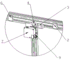
Fig. 1 is a schematic view of the overall structure of a novel double-door safety mechanism of the present invention;
fig. 2 is an enlarged schematic structural view of the left side door of the novel double-door safety mechanism of the present invention when opened;
fig. 3 is the enlarged schematic structural diagram of the left side door of the novel double-door safety mechanism after being opened.
In the drawings, 1: left side door, 2: limiting blocks a, 3: push block, 4: rotation stopper, 5: section bar door frame, 6: limiting block b, 7: safety door lock core, 8: right door, 9: the emergency exit lock bolt.
Detailed Description
The technical solution in the embodiments of the present invention will be clearly and completely described below with reference to the drawings in the embodiments of the present invention, and it is obvious that the described embodiments are only some embodiments of the present invention, rather than all embodiments, and all other embodiments obtained by a person of ordinary skill in the art without creative work belong to the protection scope of the present invention based on the embodiments of the present invention.
In the description of the present invention, it is to be understood that the terms "upper", "lower", "front", "rear", "left", "right", "top", "bottom", "inner", "outer", and the like indicate orientations or positional relationships based on the orientations or positional relationships shown in the drawings, and are only for convenience of description and simplicity of description, and do not indicate or imply that the device or element being referred to must have a particular orientation, be constructed and operated in a particular orientation, and therefore, should not be construed as limiting the present invention.
Referring to fig. 1-3, a novel double-door safety mechanism comprises a left side door 1, a limiting block a2, a pushing block 3, a rotary stop block 4, a sectional material door frame 5, a limiting block b6, a safety door lock cylinder 7, a right side door 8 and a safety door lock pin 9, wherein the safety door lock pin 9 is arranged on the left side of the front end surface of the left side door 1, the safety door lock pin 9 is fixed on the left side door 1 through screws, the right side door 8 is arranged on the left side of the left side door 1, the safety door lock cylinder 7 is arranged on the right side of the front end surface of the right side door 8, the safety door lock cylinder 7 is fixed on the right side door 8 through screws, the safety door lock pin 9 is connected with the safety door lock cylinder 7 in a locking manner, the pushing block 3 is arranged above the safety door lock pin 9, the pushing block 3 is installed on the left side door 1, the rotary stop block 4, the rotary stop block 4 is rotatably mounted on a right side door 8 through an equal-height screw, the push block 3 limits the rotary stop block 4 to rotate when the left side door 1 is not opened, the upper part of the rotary stop block 4 is clamped on the profile door frame 5 when the rotary stop block 4 is not rotated, the left side door 1 and the right side door 8 are arranged in a frame of the profile door frame 5, the right side of the profile door frame 5 is provided with a limit block a2 for limiting the closing position of the left side door 1, the limit block a2 is fixed on the profile door frame 5 through a screw, the left side of the profile door frame 5 is provided with a limit block b6 for limiting the closing position of the right side door 8, the limit block b6 is fixed on the profile door frame 5 through a screw, the lateral force borne by the safety door lock cylinder 7 is within the lateral force bearing range, and a set of safety door locks are used for the left side door 1 and the right, the brands of the safety door lock core 7 and the safety door lock bolt 9 are not limited to OMRON, AnShinen, PILZ and the like.
The left side door 1 and the right side door 8 are arranged inside a frame of the sectional material door frame 5, a safety door lock bolt 9 is arranged on one side, close to the right side door 8, of the front side surface of the left side door 1, a safety door lock cylinder 7 is arranged on one side, close to the left side door 1, of the front side of the right side door 8, the safety door lock bolt 9 is locked and inserted into the safety door lock cylinder 7 from one side in a state that the left side door 1 and the right side door 8 are closed simultaneously, and at the moment, a safety switch of the safety door lock cylinder 7 can output signals, so that the situation that a common double-door single lock has; the limiting block a2 is fixedly installed at the right side position of the profile door frame 5 through screws, the lower part of the limiting block a2 limits the opening position of the left side door 1 to be parallel and level with the edge of the profile door frame 5, the limiting block b6 is fixedly installed at the left side position of the profile door frame 5 through screws, the lower part of the limiting block b6 limits the opening position of the right side door 8 to be parallel and level with the edge of the profile door frame 5, the closing positions of the left side door 1 and the right side door 8 can be limited through the limiting block a2 and the limiting block b6, the rotating block 4 is tightly attached to the profile door frame 5, the outward opening force of the right side door 8 is transmitted to the profile door frame 5 through the rotating block 4, the lateral force received by the safety door lock cylinder 7 is within the.
The safety door lock pin 9 is unlocked from the safety door lock cylinder 7, the safety switch of the safety door lock cylinder 7 has no safety locking signal output, before the left door 1 is opened, the pushing block 3 on the left door 1 limits the rotation of the rotary stop block 4, the upper part of the rotary stop block 4 is blocked by the profile door frame 5, so that the right door 8 is limited to be opened, after the left door 1 is opened, the rotary stop block 4 is not limited by the pushing block, under the condition that the right door 8 is pushed by external force, the rotary stop block rotates to a position which does not interfere with the profile door frame 5, the right door can be opened, through the mutual limitation of the left door 1 and the right door 8, the double-door only uses one set of safety door locks, the manufacturing cost of equipment is reduced, the right door 8 and the left door 1 can only be opened in sequence, the influence of inertia force is prevented, and the independence of the left door 1 and the right door 8 is further ensured.
A novel double-door safety mechanism is characterized in that a left side door 1 and a right side door 8 are rotatably arranged in a frame of a section bar door frame 5 through hinges, a safety door lock cylinder 7 is connected with a power box through a power line, and the power box controls the transmission of safety signals of the safety door lock cylinder 7 and the connection or the disconnection of the safety door lock cylinder 7 and a safety door lock bolt 9; when the left side door 1 is opened, the safety door lock bolt 9 is pulled out of the safety door lock cylinder 7, the safety door lock cylinder 7 on the right side door 8 is subjected to outward opening force, and the lateral force applied to the safety door lock cylinder 7 is within the range of the lateral force borne by the safety door lock cylinder, so that the service life of the safety door lock is ensured; before the left side door 1 is opened, the rotating stop block 4 on the right side door 8 is limited by the pushing block 3 on the left side door 1 to rotate, the upper part of the rotating stop block 4 is stopped by the profile doorframe 5, the rotating stop block 4 is tightly attached to the profile doorframe 5, and the outward opening force of the right side door 8 is transmitted to the profile doorframe 5 by the rotating stop block 4, so that the right side door 8 cannot be opened; after the left side door 1 is opened, the rotary stop block 4 is not limited by the pushing block 3, under the condition that the right side door 8 is pushed by external force, the rotary stop block 4 rotates to the position where the upper part does not interfere with the section bar door frame 5, the right side door 8 can be opened, and by using simple mechanical parts, the double-door structure only uses one set of safety door lock, so that the manufacturing cost of equipment is reduced, and the double-door safety mechanism meets the relevant standards of mechanical safety protection in China.
Having shown and described the basic principles and principal features of the invention and advantages thereof, it will be apparent to those skilled in the art that the invention is not limited to the details of the foregoing exemplary embodiments, but is capable of other specific forms without departing from the spirit or essential characteristics thereof; the present embodiments are therefore to be considered in all respects as illustrative and not restrictive, the scope of the invention being indicated by the appended claims rather than by the foregoing description, and all changes which come within the meaning and range of equivalency of the claims are therefore intended to be embraced therein, and any reference signs in the claims are not intended to be construed as limiting the claim concerned.
Furthermore, it should be understood that although the present description refers to embodiments, not every embodiment may contain only a single embodiment, and such description is for clarity only, and those skilled in the art should integrate the description, and the embodiments may be combined as appropriate to form other embodiments understood by those skilled in the art.
Claims (6)
1. The utility model provides a novel two safety mechanism that open door which characterized in that: comprises a left side door (1), a limit block a (2), a pushing block (3), a rotary stop block (4), a section bar door frame (5), a limit block b (6),
The safety door lock comprises a safety door lock cylinder (7), a right side door (8) and a safety door lock bolt (9), wherein the safety door lock bolt (9) is arranged on the left side of the front end surface of the left side door (1), the safety door lock bolt (9) is fixed on the left side door (1) through screws, the right side door (8) is arranged on the left side of the left side door (1), the safety door lock cylinder (7) is arranged on the right side of the front end surface of the right side door (8), the safety door lock cylinder (7) is fixed on the right side door (8) through screws, the safety door lock bolt (9) is in locking connection with the safety door lock cylinder (7), a pushing block (3) is arranged above the safety door lock bolt (9), the pushing block (3) is installed on the left side door (1), a rotary stop block (4) is arranged above the safety door lock cylinder (7), and the rotary stop block (4) is rotatably installed on the right side door (8, promote piece (3) and be in restriction under the state that left side door (1) did not open rotatory dog (4) rotate, upper portion joint is in under the irrotational state rotatory dog (4) on section bar door frame (5), left side door (1) with right side door (8) set up in the frame of section bar door frame (5), section bar door frame (5) right side is equipped with stopper a (2) that are used for restricting left side door (1) closed door position, stopper a (2) pass through the screw fixation on section bar door frame (5), section bar door frame (5) left side is equipped with stopper b (6) that are used for restricting right side door (8) closed door position, stopper b (6) pass through the screw fixation on section bar door frame (5).
2. A novel double door safety mechanism as claimed in claim 1, wherein: and the limiting block a (2) limits the closing position of the left side door (1) to be attached to the edge of the section door frame (5).
3. A novel double door safety mechanism as claimed in claim 1, wherein: and the limiting block b (6) limits the closing position of the right side door (8) to be attached to the edge of the section door frame (5).
4. A novel double door safety mechanism as claimed in claim 1, wherein: the side force to which the lock core (7) of the safety door lock is subjected is within the range of the side force to which the lock core is subjected.
5. A novel double door safety mechanism as claimed in claim 1, wherein: the left side door (1) and the right side door (8) use a set of safety door lock cylinders (7).
6. A novel double door safety mechanism as claimed in claim 1, wherein: the brand of the safety door lock core (7) and the safety door lock bolt (9) is not limited to OMRON, Anshineng, PILZ and the like.
Priority Applications (1)
| Application Number | Priority Date | Filing Date | Title |
|---|---|---|---|
| CN201922306540.3U CN211369912U (en) | 2019-12-20 | 2019-12-20 | Novel double-door safety mechanism |
Applications Claiming Priority (1)
| Application Number | Priority Date | Filing Date | Title |
|---|---|---|---|
| CN201922306540.3U CN211369912U (en) | 2019-12-20 | 2019-12-20 | Novel double-door safety mechanism |
Publications (1)
| Publication Number | Publication Date |
|---|---|
| CN211369912U true CN211369912U (en) | 2020-08-28 |
Family
ID=72165372
Family Applications (1)
| Application Number | Title | Priority Date | Filing Date |
|---|---|---|---|
| CN201922306540.3U Active CN211369912U (en) | 2019-12-20 | 2019-12-20 | Novel double-door safety mechanism |
Country Status (1)
| Country | Link |
|---|---|
| CN (1) | CN211369912U (en) |
-
2019
- 2019-12-20 CN CN201922306540.3U patent/CN211369912U/en active Active
Similar Documents
| Publication | Publication Date | Title |
|---|---|---|
| CN211369912U (en) | Novel double-door safety mechanism | |
| CN213297712U (en) | Single open wood door of pick-proof opening | |
| CN208534202U (en) | A kind of subway shield door lock improving manual unlocking structure | |
| CN208106127U (en) | A kind of door lock with automatic lock function | |
| CN211115311U (en) | Door lock for enclosure movable door | |
| CN210483316U (en) | U-shaped lock body structure | |
| CN209620807U (en) | A kind of Novel lock body clutch structure that band resets | |
| CN208267557U (en) | A kind of Fingerprint Lock | |
| CN201771383U (en) | Novel anti-theft door | |
| CN202493114U (en) | Two-way crescent lock convenient to reverse | |
| CN219993530U (en) | Anti-theft door capable of preventing hand from being clamped | |
| CN2376521Y (en) | Double-wing door lock | |
| CN219241584U (en) | Single-bolt lock body with back-locking function | |
| CN220667224U (en) | Lockset for side-hung door | |
| CN213359863U (en) | Anti-picking lock anti-theft door with shield | |
| CN221031958U (en) | Reinforced lock catch of safe | |
| CN2486697Y (en) | Double open anti-pick door | |
| CN220955067U (en) | Dual-mode power lock with position switch | |
| CN210977222U (en) | Connecting device for mounting primary and secondary doors | |
| CN203271550U (en) | Electrically controlled brake anti-theft rolling door | |
| CN205314690U (en) | Austral window, sliding sash safety anti theft lock | |
| CN2418211Y (en) | Anti-theft lock for anti-theft door | |
| CN216903830U (en) | Anti-electricity-theft low-voltage cabinet | |
| CN201343273Y (en) | Special door of car container | |
| CN213175158U (en) | Automatic lock capable of preventing locking |
Legal Events
| Date | Code | Title | Description |
|---|---|---|---|
| GR01 | Patent grant | ||
| GR01 | Patent grant |