CN211360837U - Radiator sliding cutting die - Google Patents
Radiator sliding cutting die Download PDFInfo
- Publication number
- CN211360837U CN211360837U CN201922476497.5U CN201922476497U CN211360837U CN 211360837 U CN211360837 U CN 211360837U CN 201922476497 U CN201922476497 U CN 201922476497U CN 211360837 U CN211360837 U CN 211360837U
- Authority
- CN
- China
- Prior art keywords
- sliding cutting
- sliding
- cutting
- rotating shaft
- driving
- Prior art date
- Legal status (The legal status is an assumption and is not a legal conclusion. Google has not performed a legal analysis and makes no representation as to the accuracy of the status listed.)
- Active
Links
Images

Abstract
The utility model discloses a radiator sliding cutting die, cut fixed plate, sliding cutting drive arrangement, sliding cutting degree of depth regulating part, fixed compressing tightly piece, reverse accelerated sliding cutting drive arrangement and the smooth cutter of rolling including last sliding, on sliding cutting degree of depth regulating part locates sliding cutting fixed plate upper wall down, it locates on the sliding cutting degree of depth regulating part to go up the sliding cutting fixed plate, sliding cutting drive arrangement locates on the sliding cutting fixed plate down, fixed compressing tightly on the piece locates on the sliding cutting fixed plate diapire, reverse accelerated sliding cutting drive arrangement locates in the sliding cutting fixed plate, the smooth cutter of rolling is located on the reverse accelerated sliding cutting drive arrangement. The utility model belongs to the technical field of the radiator processing, specifically a radiator sliding cutting die can carry out the smooth operation of cutting of transmission in opposite directions to the radiator, has improved smooth speed and the accuracy of cutting, and effectual solved present market sliding cutting die work efficiency lower, and self structure is complicated, maintains comparatively inconvenient problem.
Description
Technical Field
The utility model belongs to the technical field of the radiator processing, specifically indicate a radiator sliding cutting die.
Background
With the constant innovation and development of mankind, time becomes more and more valuable, and for the present producers, the cost and efficiency is the most important, besides sales, all the products are produced by moulds, and the aim of improving the benefit and reducing the cost is to reduce the cost on the moulds, and the mould has the highest efficiency in production, so that the lowest cost and the highest benefit can be achieved, the traditional moulds are processed by one procedure and one procedure, different procedures cannot be finished at the same time, thus, in the production process, the production time is prolonged, the working time and the intensity of operators are also prolonged, the cost naturally paid is increased, if the production is carried out in a large scale, the cost is very high, and the production cost is directly influenced. Moreover, the production mode not only affects the production cost and causes low production benefit and poor continuous cutting effect, but also the existing sliding cutting die can not keep the stability of materials during cutting and affects the cutting efficiency.
SUMMERY OF THE UTILITY MODEL
To the above situation, for overcoming prior art's defect, the utility model provides a radiator sliding cutting die can carry out the smooth operation of cutting of transmission in opposite directions to the radiator, has improved smooth speed and the accuracy of cutting, and effectual solved present market sliding cutting die work efficiency is lower, and self structure is complicated, maintains comparatively inconvenient problem.
The utility model adopts the following technical scheme: the utility model relates to a radiator sliding cutting die, including last sliding cutting fixed plate, lower sliding cutting fixed plate, sliding cutting drive arrangement, sliding cutting depth regulating part, fixed pressing member, reverse acceleration sliding cutting drive arrangement and rolling sliding cutting tool, sliding cutting depth regulating part locates on the upper wall of lower sliding cutting fixed plate, last sliding cutting fixed plate locates on the sliding cutting depth regulating part, sliding cutting drive arrangement locates on lower sliding cutting fixed plate, fixed pressing member locates on last sliding cutting fixed plate bottom wall, reverse acceleration sliding cutting drive arrangement locates in last sliding cutting fixed plate, rolling sliding cutting tool locates on reverse acceleration sliding cutting drive arrangement; the rolling sliding cutting tool comprises a sliding cutting tool supporting plate, a rolling sliding cutting shaft and a sliding cutting tool, the sliding cutting tool supporting plate is arranged on the reverse accelerating sliding cutting driving device, the rolling sliding cutting shaft is rotatably arranged on the sliding cutting tool supporting plate, and the sliding cutting tool is sleeved on the rolling sliding cutting shaft.
Further, reverse smooth drive arrangement that surely cuts with higher speed is including smooth pivot, smooth gear, smooth rack frame of cutting, smooth motor mounting and the smooth motor of cutting, smooth rack frame slides and locates on the inboard diapire of reverse smooth drive arrangement that cuts with higher speed, smooth motor mounting of cutting is located on the inboard diapire of reverse smooth drive arrangement that cuts with higher speed and is located smooth rack frame one side of cutting, smooth motor of cutting is located on the smooth motor mounting of cutting, smooth pivot rotation of cutting is located on the reverse smooth drive arrangement lateral wall that cuts with higher speed, the output shaft and the smooth pivot of cutting of smooth motor of cutting link to each other, the smooth gear cover of cutting connects and locates in the smooth pivot of cutting, the smooth pivot of cutting links to each other with the meshing of smooth rack frame of cutting.
Furthermore, sawteeth are arranged on the circumferential wall of the sliding cutting rotating shaft.
Further, it includes drive pivot, transmission rolling wheel, transmission belt, driving motor mounting and driving motor to slide the drive arrangement, the driving motor mounting is located down and is cut fixed plate one side, driving motor locates on the driving motor mounting, the drive pivot is rotated and is located down and slide on two non-adjacent lateral walls of cut fixed plate, the transmission rolling wheel cup joints and locates on the drive pivot, the transmission belt is around connecting and locates on the drive pivot, driving motor's output links to each other with the drive pivot, driving motor rotates and drives the drive pivot and rotate, and the drive pivot rotates and drives transmission belt and rotate, and transmission belt rotates and drives transmission rolling wheel and rotate, and transmission rolling wheel rotates and drives the radiator of placing above and removes.
Furthermore, the fixed pressing pieces are arranged in a T shape, and the two groups of fixed pressing pieces are symmetrically arranged.
Furthermore, the sliding cutting depth adjusting pieces are arranged by adopting electric hydraulic push rods, and four groups of sliding cutting depth adjusting pieces are arranged.
Furthermore, the upper sliding cutting fixing plate is arranged in a rectangular hollow cavity, and the lower sliding cutting fixing plate is arranged in a concave shape.
Adopt above-mentioned structure the utility model discloses the beneficial effect who gains as follows: this scheme a radiator sliding die can carry out the smooth operation of cutting of transmission in opposite directions to the radiator, has improved smooth speed and the accuracy of cutting, and effectual having solved present market sliding die work efficiency is lower, and self structure is complicated, maintains comparatively inconvenient problem.
Drawings
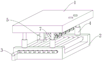
Fig. 1 is a schematic view of the overall structure of the sliding cutting die for a heat sink of the present invention;
fig. 2 is a perspective view of the sliding cutting die for heat sink of the present invention.
The device comprises an upper sliding cutting fixing plate 1, a lower sliding cutting fixing plate 2, a sliding cutting driving device 3, a sliding cutting driving device 4, a sliding cutting depth adjusting part 5, a fixed pressing part 6, a reverse accelerating sliding cutting driving device 7, a rolling sliding cutting tool 8, a sliding cutting tool supporting plate 9, a rolling sliding cutting shaft 10, a sliding cutting tool 11, a sliding cutting rotating shaft 12, a sliding cutting gear 13, a sliding cutting rack frame 14, a sliding cutting motor fixing part 15, a sliding cutting motor 16, sawteeth 17, a driving rotating shaft 18, a transmission rolling wheel 19, a transmission belt 20, a driving motor fixing part 21 and a driving motor.
The accompanying drawings are included to provide a further understanding of the invention, and are incorporated in and constitute a part of this specification, illustrate embodiments of the invention, and together with the description serve to explain the invention and not to limit the invention.
Detailed Description
The technical solutions in the embodiments of the present invention will be clearly and completely described below with reference to the drawings in the embodiments of the present invention, and it is obvious that the described embodiments are only some embodiments of the present invention, not all embodiments; based on the embodiments in the present invention, all other embodiments obtained by a person skilled in the art without creative work belong to the protection scope of the present invention.
As shown in fig. 1-2, the utility model discloses a radiator sliding cutting die, including upper sliding cutting fixed plate 1, lower sliding cutting fixed plate 2, sliding cutting drive arrangement 3, sliding cutting depth regulating part 4, fixed pressing member 5, reverse acceleration sliding cutting drive arrangement 6 and rolling sliding cutting tool 7, sliding cutting depth regulating part 4 is located on the upper wall of lower sliding cutting fixed plate 2, upper sliding cutting fixed plate 1 is located on sliding cutting depth regulating part 4, sliding cutting drive arrangement 3 is located on lower sliding cutting fixed plate 2, fixed pressing member 5 is located on the bottom wall of upper sliding cutting fixed plate 1, reverse acceleration sliding cutting drive arrangement 6 is located in upper sliding cutting fixed plate 1, rolling sliding cutting tool 7 is located on reverse acceleration sliding cutting drive arrangement 6; the rolling sliding cutting tool 7 comprises a sliding cutting tool supporting plate 8, a rolling sliding cutting shaft 9 and a sliding cutting tool 10, the sliding cutting tool supporting plate 8 is arranged on the reverse accelerating sliding cutting driving device 6, the rolling sliding cutting shaft 9 is rotatably arranged on the sliding cutting tool supporting plate 8, and the sliding cutting tool 10 is sleeved on the rolling sliding cutting shaft 9.
Reverse smooth drive arrangement 6 that surely slides with higher speed is including smooth pivot 11, smooth gear 12, the smooth rack frame 13 that cuts, smooth motor mounting 14 and smooth motor 15 that cuts, smooth rack frame 13 slides and locates on the smooth inboard diapire of drive arrangement 6 that surely cuts with higher speed of reverse, smooth motor mounting 14 that cuts is located on the smooth inboard diapire of drive arrangement 6 that surely cuts with higher speed of reverse and locates smooth rack frame 13 one side, smooth motor 15 that cuts is located on smooth motor mounting 14, smooth pivot 11 that cuts rotates and locates on the smooth drive arrangement 6 lateral wall that cuts with higher speed of reverse, the output shaft of smooth motor 15 links to each other with smooth pivot 11 that cuts, smooth gear 12 cup joints and locates on smooth pivot 11 that cuts, smooth pivot 11 that cuts links to each other with the meshing of smooth rack frame 13.
The circumferential wall of the sliding cutting rotating shaft 11 is provided with sawteeth 16.
The sliding cutting driving device 3 comprises a driving rotating shaft 17, a transmission rolling wheel 18, a transmission belt 19, a driving motor fixing piece 20 and a driving motor 21, the driving motor fixing piece 20 is arranged on one side of a sliding cutting fixing plate 2, the driving motor 21 is arranged on the driving motor fixing piece 20, the driving rotating shaft 17 is rotatably arranged on two non-adjacent side walls of the sliding cutting fixing plate 2, the transmission rolling wheel 18 is sleeved on the driving rotating shaft 17, the transmission belt 19 is wound on the driving rotating shaft 17, the output end of the driving motor 21 is connected with the driving rotating shaft 17, the driving motor 21 rotates to drive the driving rotating shaft 17 to rotate, the driving rotating shaft 17 rotates to drive the transmission belt 19 to rotate, the transmission belt 19 rotates to drive the transmission rolling wheel 18 to rotate, and the transmission rolling wheel 18 rotates to drive a radiator placed on the transmission rolling wheel to move.
The fixed pressing pieces 5 are arranged in a T shape, and the fixed pressing pieces 5 are symmetrically provided with two groups.
The sliding cutting depth adjusting piece 4 is arranged by adopting an electric hydraulic push rod, and four groups of sliding cutting depth adjusting pieces 4 are arranged.
The upper sliding cutting fixing plate 1 is arranged in a rectangular hollow cavity, and the lower sliding cutting fixing plate 2 is arranged in a concave shape.
When the device is used, a user places a radiator on a transmission rolling wheel 18, starts a driving motor 21, the driving motor 21 rotates to drive a driving rotating shaft 17 to rotate, the driving rotating shaft 17 rotates to drive a transmission belt 19 to rotate, the transmission belt 19 rotates to drive the transmission rolling wheel 18 to rotate, the transmission rolling wheel 18 rotates to drive the radiator placed on the transmission rolling wheel to move, the height of a sliding cutting depth adjusting part 4 is adjusted to meet the depth required to be subjected to sliding cutting, starts a sliding cutting motor 15, the sliding cutting motor 15 rotates to drive a sliding cutting rotating shaft 11 to rotate, the sliding cutting rotating shaft 11 rotates to drive a sliding cutting gear 12 to rotate, the sliding cutting gear 12 rotates to drive a sliding cutting rack frame 13 to move, the sliding cutting rack frame 13 drives a sliding cutting cutter supporting plate 8 to move, the sliding cutting cutter supporting plate 8 moves to drive a rolling sliding cutting shaft 9 to move, the rolling sliding cutting shaft 9 moves to drive a sliding cutting cutter 10 to move, and accordingly sliding, it is above that the utility model discloses holistic work flow, when using next time repeat this step can.
It is noted that, herein, relational terms such as first and second, and the like may be used solely to distinguish one entity or action from another entity or action without necessarily requiring or implying any actual such relationship or order between such entities or actions. Also, the terms "comprises," "comprising," or any other variation thereof, are intended to cover a non-exclusive inclusion, such that a process, method, article, or apparatus that comprises a list of elements does not include only those elements but may include other elements not expressly listed or inherent to such process, method, article, or apparatus.
Although embodiments of the present invention have been shown and described, it will be appreciated by those skilled in the art that changes, modifications, substitutions and alterations can be made in these embodiments without departing from the principles and spirit of the invention, the scope of which is defined in the appended claims and their equivalents.
The present invention and the embodiments thereof have been described above, but the description is not limited thereto, and the embodiment shown in the drawings is only one of the embodiments of the present invention, and the actual structure is not limited thereto. In summary, those skilled in the art should understand that they should not be limited to the embodiments described above, and that they can design the similar structure and embodiments without departing from the spirit of the invention.
Claims (7)
1. The utility model provides a radiator sliding cutting mould which characterized in that: the device comprises an upper sliding cutting fixing plate, a lower sliding cutting fixing plate, a sliding cutting driving device, a sliding cutting depth adjusting piece, a fixed pressing piece, a reverse accelerating sliding cutting driving device and a rolling sliding cutting tool, wherein the sliding cutting depth adjusting piece is arranged on the upper wall of the lower sliding cutting fixing plate; the rolling sliding cutting tool comprises a sliding cutting tool supporting plate, a rolling sliding cutting shaft and a sliding cutting tool, the sliding cutting tool supporting plate is arranged on the reverse accelerating sliding cutting driving device, the rolling sliding cutting shaft is rotatably arranged on the sliding cutting tool supporting plate, and the sliding cutting tool is sleeved on the rolling sliding cutting shaft.
2. The die for sliding cutting a heat sink as claimed in claim 1, wherein: the reverse accelerated sliding cutting driving device comprises a sliding cutting rotating shaft, a sliding cutting gear, a sliding cutting rack frame, a sliding cutting motor fixing piece and a sliding cutting motor, wherein the sliding cutting rack frame is arranged on the inner side bottom wall of the reverse accelerated sliding cutting driving device in a sliding mode, the sliding cutting motor fixing piece is arranged on the inner side bottom wall of the reverse accelerated sliding cutting driving device in a sliding mode and is arranged on one side of the sliding cutting rack frame, the sliding cutting motor is arranged on the sliding cutting motor fixing piece, the sliding cutting rotating shaft is arranged on the side wall of the reverse accelerated sliding cutting driving device in a rotating mode, the output shaft of the sliding cutting motor is connected with the sliding cutting rotating shaft, the sliding cutting gear is sleeved on the sliding cutting rotating shaft, and the sliding cutting rotating shaft is connected with the sliding cutting rack frame.
3. The die for sliding cutting a heat sink as claimed in claim 2, wherein: the circumferential wall of the sliding cutting rotating shaft is provided with sawteeth.
4. A heat sink die of claim 3, wherein: the sliding cutting driving device comprises a driving rotating shaft, a transmission rolling wheel, a transmission belt, a driving motor fixing piece and a driving motor, wherein the driving motor fixing piece is arranged on one side of a sliding cutting fixing plate, the driving motor is arranged on the driving motor fixing piece, the driving rotating shaft is rotated and arranged on two non-adjacent side walls of the sliding cutting fixing plate, the transmission rolling wheel is sleeved and arranged on the driving rotating shaft, the transmission belt is wound and arranged on the driving rotating shaft, and the output end of the driving motor is connected with the driving rotating shaft.
5. The die of claim 4, wherein: the fixed pressing piece is arranged in a T shape, and the fixed pressing piece is symmetrically provided with two groups.
6. The die of claim 5, wherein: the sliding cutting depth adjusting pieces are arranged by adopting electric hydraulic push rods, and four groups of sliding cutting depth adjusting pieces are arranged.
7. The die as claimed in claim 6, wherein: the upper sliding cutting fixing plate is arranged in a rectangular hollow cavity, and the lower sliding cutting fixing plate is arranged in a concave shape.
Priority Applications (1)
| Application Number | Priority Date | Filing Date | Title |
|---|---|---|---|
| CN201922476497.5U CN211360837U (en) | 2019-12-31 | 2019-12-31 | Radiator sliding cutting die |
Applications Claiming Priority (1)
| Application Number | Priority Date | Filing Date | Title |
|---|---|---|---|
| CN201922476497.5U CN211360837U (en) | 2019-12-31 | 2019-12-31 | Radiator sliding cutting die |
Publications (1)
| Publication Number | Publication Date |
|---|---|
| CN211360837U true CN211360837U (en) | 2020-08-28 |
Family
ID=72161699
Family Applications (1)
| Application Number | Title | Priority Date | Filing Date |
|---|---|---|---|
| CN201922476497.5U Active CN211360837U (en) | 2019-12-31 | 2019-12-31 | Radiator sliding cutting die |
Country Status (1)
| Country | Link |
|---|---|
| CN (1) | CN211360837U (en) |
Cited By (1)
| Publication number | Priority date | Publication date | Assignee | Title |
|---|---|---|---|---|
| CN114311332A (en) * | 2021-11-16 | 2022-04-12 | 海洋石油工程股份有限公司 | Novel efficient submarine pipeline concrete counter weight layer slotting device |
-
2019
- 2019-12-31 CN CN201922476497.5U patent/CN211360837U/en active Active
Cited By (1)
| Publication number | Priority date | Publication date | Assignee | Title |
|---|---|---|---|---|
| CN114311332A (en) * | 2021-11-16 | 2022-04-12 | 海洋石油工程股份有限公司 | Novel efficient submarine pipeline concrete counter weight layer slotting device |
Similar Documents
| Publication | Publication Date | Title |
|---|---|---|
| CN206912332U (en) | A kind of sheet fabrication cutting machine | |
| CN211360837U (en) | Radiator sliding cutting die | |
| CN210791786U (en) | Processingequipment of bank protection brick mould | |
| CN209732434U (en) | Oil bar drawing machine | |
| CN208601598U (en) | For sheet fabrication molding cutter structure | |
| CN103416448A (en) | Full-automatic dough slicing machine | |
| CN210362311U (en) | Water gap separator | |
| CN212887756U (en) | Cutting die | |
| CN211247905U (en) | Part punching and shearing device | |
| CN208408744U (en) | A kind of multifunction automatic mould steel chamfering device | |
| CN112568267A (en) | Processing equipment for meat product production | |
| CN108188427B (en) | It is a kind of with the hardware dies puncher for stepping up function automatically | |
| CN206028878U (en) | A cutting machine for fan shell | |
| CN210160852U (en) | Grinding device is used in gear shaft production and processing | |
| CN220718467U (en) | Multi-angle automatic cutting device of die steel | |
| CN219006250U (en) | Automatic feeding and dicing device | |
| CN216423187U (en) | Multi-functional plastic product processingequipment | |
| CN213907579U (en) | Straw cutter for modern agriculture | |
| CN109821973A (en) | A kind of punch die tooling for workpiece essence hole machined | |
| CN219835173U (en) | Extruder is used in skin of beancurd processing | |
| CN219211405U (en) | Stamping die for door hinge | |
| CN216493150U (en) | Automatic processing device for air-dried beef and mutton | |
| CN217618029U (en) | Raw material cutting device for gear machining | |
| CN217751618U (en) | Double-turntable edge trimmer | |
| CN219563286U (en) | Slicer is used in mutton processing |
Legal Events
| Date | Code | Title | Description |
|---|---|---|---|
| GR01 | Patent grant | ||
| GR01 | Patent grant |