CN211331367U - U-shaped groove machining tool - Google Patents
U-shaped groove machining tool Download PDFInfo
- Publication number
- CN211331367U CN211331367U CN201921645135.8U CN201921645135U CN211331367U CN 211331367 U CN211331367 U CN 211331367U CN 201921645135 U CN201921645135 U CN 201921645135U CN 211331367 U CN211331367 U CN 211331367U
- Authority
- CN
- China
- Prior art keywords
- cutter
- head
- cutter head
- shaped groove
- bar
- Prior art date
- Legal status (The legal status is an assumption and is not a legal conclusion. Google has not performed a legal analysis and makes no representation as to the accuracy of the status listed.)
- Active
Links
Images

Landscapes
- Milling Processes (AREA)
Abstract
The utility model discloses a U type groove processing cutter, including supporter (1), cutter arbor (2), tool bit (5), its characterized in that: the cutter bar (2) is connected onto the support body (1), the cutter head (5) is detachably mounted at the head of the cutter bar (2), the head of the cutter head (5) is provided with a circular arc-shaped cutting edge with a radius R, the cutter head (5) is connected with a groove on the cutter bar (2) in a matched mode through a set convex block (4), and a fastening screw (3) is connected between the cutter bar (2) and the cutter head (5). The utility model discloses simple structure, high-efficient use, commonality are strong, convenient operation, are fit for using widely of inside U type groove processing.
Description
Technical Field
The utility model belongs to the technical field of the processing cutter, a U type groove processing cutter is related to particularly.
Background
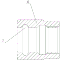
In the production process, the U-shaped groove is an indispensable structure in various parts. The U-shaped groove is processed, particularly the U-shaped groove (as shown in figure 3) in a product such as a jacket nut, by using a forming blade to process the U-shaped groove by a program, the time consumption is too long; if a common lathe is used for processing, the efficiency is extremely low, and the operation is inconvenient. Under the condition of using a large amount of automatic equipment, the existing machining tool for the U-shaped groove is not suitable for production requirements.
Disclosure of Invention
The utility model aims to overcome above-mentioned shortcoming and provide a simple structure, high-efficient use, commonality are strong, convenient operation's U type groove processing cutter.
The utility model discloses the purpose and solve its main technical problem and adopt following technical scheme to realize:
the utility model discloses a U type groove processing cutter, including supporter, cutter arbor, tool bit, wherein: the supporting body is connected with a cutter bar, the head of the cutter bar is detachably provided with a cutter head, and the head of the cutter head is provided with a circular arc-shaped cutting edge with the radius R.
Above-mentioned U type groove processing cutter, wherein: the cutter head is connected with the groove on the cutter bar in a matching way through the arranged convex block.
Above-mentioned U type groove processing cutter, wherein: a fastening screw is connected between the cutter bar and the cutter head.
Compared with the prior art, the utility model obvious advantage and beneficial effect have. According to the technical scheme, in the U-shaped groove machining tool, the head part of the tool bit is provided with the arc-shaped cutting edge with the radius R, so that the U-shaped groove with the radius R is machined and generated by the tool at one time, and the operation is efficient and feasible; the cutter head is matched and connected with the groove in the cutter rod through the convex block, so that the cutter rod and the cutter head can be detached, the cutter head can be conveniently selected according to requirements, the replaceability is strong, and the cutter head is only required to be replaced instead of the whole body after being damaged, so that the economy is improved; and a fastening screw is connected between the cutter bar and the cutter head, so that the connection stability of the cutter bar and the cutter head is further improved. In a word, the utility model discloses simple structure, high-efficient use, commonality are strong, convenient operation, are fit for using widely of inside U type groove processing.
Drawings
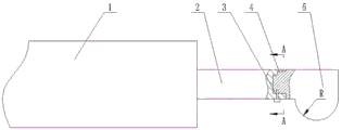
Fig. 1 is a schematic structural view of the present invention;
FIG. 2 is a cross-sectional view along AA of FIG. 1;
fig. 3 is a schematic structural view of a nut to be processed.
The labels in the figure are:
1. a support body; 2. a cutter bar; 3. fastening screws; 4. a convex block; 5. a cutter head; 6. a nut to be processed; 7. a U-shaped groove.
Detailed Description
The following detailed description of the embodiments, structures, features and effects of the U-shaped groove machining tool according to the present invention will be made with reference to the accompanying drawings and preferred embodiments.
Referring to fig. 1 to 2, the utility model discloses a U type groove processing cutter, including supporter 1, cutter arbor 2, tool bit 5, wherein: be connected with cutter arbor 2 on the supporter 1, cutter head 5 is installed to cutter arbor 2's head detachably, and cutter head 5 head is provided with radius R's convex cutting edge. The cutter head 5 is matched and connected with the groove on the cutter rod 2 through the arranged convex block 4. A fastening screw 3 is connected between the cutter bar 2 and the cutter head 5.
During the use, select the tool bit 5 of suitable specification cutting edge according to the radius size of U type groove 7 in waiting to process nut 6 earlier, install tool bit 5 at 2 heads of cutter arbor and fasten through fastening screw 3, then fix supporter 1 to the processing organism, adjust the cutting parameter of processing cutter through the lathe, can carry out the processing in U type groove. The utility model discloses simple structure, high-efficient use, commonality are strong, convenient operation, are fit for using widely of inside U type groove processing.
The above description is only a preferred embodiment of the present invention, and is not intended to limit the present invention in any form, and any simple modification, equivalent change and modification made by the technical spirit of the present invention to the above embodiments do not depart from the technical solution of the present invention.
Claims (3)
1. The utility model provides a U type groove processing cutter, includes supporter (1), cutter arbor (2), tool bit (5), its characterized in that: the supporting body (1) is connected with a cutter bar (2), the head of the cutter bar (2) is detachably provided with a cutter head (5), and the head of the cutter head (5) is provided with a circular arc-shaped cutting edge with the radius R.
2. The U-shaped groove machining tool according to claim 1, wherein: the cutter head (5) is matched and connected with the groove on the cutter bar (2) through the arranged convex block (4).
3. The U-shaped groove machining tool according to claim 1, wherein: a fastening screw (3) is connected between the cutter bar (2) and the cutter head (5).
Priority Applications (1)
| Application Number | Priority Date | Filing Date | Title |
|---|---|---|---|
| CN201921645135.8U CN211331367U (en) | 2019-09-29 | 2019-09-29 | U-shaped groove machining tool |
Applications Claiming Priority (1)
| Application Number | Priority Date | Filing Date | Title |
|---|---|---|---|
| CN201921645135.8U CN211331367U (en) | 2019-09-29 | 2019-09-29 | U-shaped groove machining tool |
Publications (1)
| Publication Number | Publication Date |
|---|---|
| CN211331367U true CN211331367U (en) | 2020-08-25 |
Family
ID=72089076
Family Applications (1)
| Application Number | Title | Priority Date | Filing Date |
|---|---|---|---|
| CN201921645135.8U Active CN211331367U (en) | 2019-09-29 | 2019-09-29 | U-shaped groove machining tool |
Country Status (1)
| Country | Link |
|---|---|
| CN (1) | CN211331367U (en) |
Cited By (1)
| Publication number | Priority date | Publication date | Assignee | Title |
|---|---|---|---|---|
| CN110653384A (en) * | 2019-09-29 | 2020-01-07 | 中国航空工业标准件制造有限责任公司 | U-shaped groove machining tool |
-
2019
- 2019-09-29 CN CN201921645135.8U patent/CN211331367U/en active Active
Cited By (1)
| Publication number | Priority date | Publication date | Assignee | Title |
|---|---|---|---|---|
| CN110653384A (en) * | 2019-09-29 | 2020-01-07 | 中国航空工业标准件制造有限责任公司 | U-shaped groove machining tool |
Similar Documents
| Publication | Publication Date | Title |
|---|---|---|
| CN211331367U (en) | U-shaped groove machining tool | |
| CN204711219U (en) | A kind of double-headstock numerically controlled lathe adjustable blade holders | |
| CN201684936U (en) | Tailored reverse turning tool | |
| CN201161297Y (en) | Bridge type inverse boring tool | |
| CN110653384A (en) | U-shaped groove machining tool | |
| CN213945040U (en) | Double-edge aluminum milling cutter with chip grooves | |
| CN203888041U (en) | Special cutter for machining slender graphite rod | |
| CN210548183U (en) | Adjustable lathe tool | |
| CN210115469U (en) | Conical curve single-positioning deep groove cutter bar and mounting structure | |
| CN208051010U (en) | Lock dentition formula high-efficiency multi-function milling head | |
| CN215845909U (en) | Reverse countersinking tool with replaceable blade | |
| CN214920819U (en) | Fine milling cutter disc | |
| CN110587028A (en) | Disposable cutting device for whole bundle binding of steel bars | |
| CN204545592U (en) | A kind of Novel bolt beveler | |
| CN221434968U (en) | Efficient machining cutter for hole wall supporting rate of piston hole | |
| CN205129048U (en) | Deep hole eccentric grove processing isolated plant | |
| CN208304044U (en) | A kind of screwdriver bit process tool | |
| CN203600264U (en) | Trimming knife of photovoltaic module | |
| CN217529508U (en) | High-precision thread milling cutter convenient to install and based on aero-engine | |
| CN217571031U (en) | Adjustable face milling cutter handle special for aluminum product | |
| CN210878565U (en) | High-stability workbench for numerical control machine tool | |
| CN210937171U (en) | Hanging wheel frame for assembling vertical numerical control machine tool | |
| CN211304937U (en) | Radian molding cutter head | |
| CN216176708U (en) | Adjustable cutter arbor | |
| CN221516235U (en) | Cemented carbide end mill convenient to adjust and change |
Legal Events
| Date | Code | Title | Description |
|---|---|---|---|
| GR01 | Patent grant | ||
| GR01 | Patent grant |